1
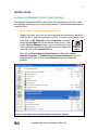
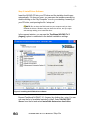
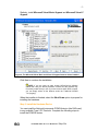
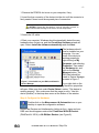
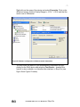
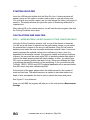
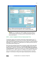
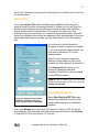
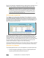
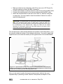
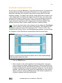
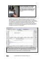
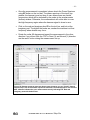
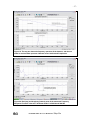
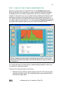
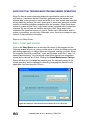
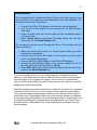
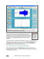
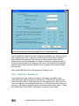
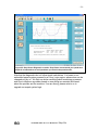
-1- MAL MANUFACTURING AUTOMATION LABORATORIES INC. 2829 Highbury St., Vancouver, B.C. CANADA V6R 3T7, http://www.malinc.com/ Tel.: (604) 228 9213, Fax: (604) 228 9269 Shop-Pro Manual © MAL Manufacturing Automation Laboratories Inc. July 2006 INTRODUCTION Shop-Pro was designed to implement basic principles of advanced machining engineering of MAL’s CUTPRO software at the shops by practicing machining process planners, engineers and operators. Shop-Pro is not as detailed as CUTPRO, which can accurately analyze machining operations with complex tools, but it can rapidly allow users to benefit from the chatter stability lobe prediction feature of CUTPRO. Shop-Pro is a completely integrated one-shot program that contains impact hammer test, chatter stability-torque-powermaterial removal prediction and machining diagnostics in seamless software. Furthermore, Shop-Pro is equipped with an expert machining troubleshooter and advisory module. Shop Doctor queries the problems experienced in the shop, and uses the impact hammer measurements, sound recording of the machining process, and advises the user as to what might have gone wrong and how to overcome the vibration, excessive tool wear, and tolerance violations. It takes only a few minutes to learn Shop-Pro. Please use the following quick guide before using the Shop-Pro in practice. 07/06/2006 MAL Inc. User Manual for Shop-Pro -2- INSTALLATION NATIONAL INSTRUMENTS DATA ACQUISITION (DAQ) The National Instruments DAQ is used as an interface between the I/O box and the computer, allowing you to collect measurements. Please follow these steps to install the DAQ. Step 1: Remove Previously Installed Drivers Please first make sure that you have removed any previously installed NI DAQ drivers to avoid any potential conflicts. To remove your drivers, first right click on My Computer, select Properties, and then select the Hardware tab on the window that pops up. Click on the Device Manager button, and you should see your Figure 1: DAQ card listed under Data Acquisition devices. Select the Uninstall card and click on the Uninstall button. button Next, go to Start>Settings>Control Panel and then open Add or Remove Programs. Find National Instruments Software in the list of programs and select it. Click on the Remove button and follow the prompts. Figure 2: Click Remove to uninstall the National Instruments Software 07/06/2006 MAL Inc. User Manual for Shop-Pro -3Step 2: Install Driver Software Insert the NI-DAQ CD into your CD drive and the installer should open automatically. If it does not open, you can open the installer manually by double clicking on the “My Computer” icon on your desktop, browsing to your CD drive, and opening the file “setup.exe”. NOTE: Do not insert the DAQ card into your computer until you have installed the drivers. Windows may not detect the device, and you might see warnings asking you to install the driver. In the opened window, you can see the Traditional NI-DAQ 7.4.1 (Legacy) option is unselected in the default installation settings. Figure 3: Installing the NI DAQ driver software. Expand Traditional NI-DAQ 7.4.1 (Legacy) by clicking the + sign. You can now see the list of available features to install. Select NI-DAQ OPC Server from the list and select Install this feature to a local drive. 07/06/2006 MAL Inc. User Manual for Shop-Pro -4- Figure 4: Selecting install for the NI-DAQ OPC Server Figure 5: The NI-DAQ OPC Server feature will be installed 07/06/2006 MAL Inc. User Manual for Shop-Pro -5Similarly, install Microsoft Visual Basic Support and Microsoft Visual C Support. Figure 6: The Microsoft Visual Basic and Visual C Support features will be installed Click Next to continue the installation. NOTE: If you are using an older version NI-DAQ driver software (earlier than v8.0), the above procedure is similar, but the graphics may not exactly match what you see. If you are not sure which items to install, you can simply select all the features under the Traditional NI-DAQ 7.4.1(Legacy). When the installer is finished, select the Shut Down option to prepare for installing the hardware. Step 3: Install the Hardware Device You can install the National Instruments PCMCIA device (the DAQ card) in any available Type II PC Card slot. Complete the following steps to install the PCMCIA device: 07/06/2006 MAL Inc. User Manual for Shop-Pro -61. Remove the PCMCIA slot cover on your computer, if any. 2. Insert the bus connector of the device into the slot until the connector is firmly seated. Never touch the exposed pins of connectors. CAUTION: Please take precautions, such as grounding yourself, to prevent electrostatic damage to the device and its components. 3. Attach the I/O cable. 4. Start your computer. Windows should automatically detect the new hardware when it starts up, and the Found New Hardware wizard will open. Select Install the software automatically and click Next. The hardware should now be installed on your computer. You can check if the device is working properly by right-clicking on My Computer, and selecting Properties. Then select the Hardware tab, and click on the Device Manager button. The DAQ card should be listed in Device Manager, as seen in Figure 7. Figure 7: You should see your DAQ card listed in Device Manager If you right-click on the device and select Properties, a window displaying the device properties will open. Make sure that under Device Status it states, “This device is working properly.” Also, make sure that the usage is set to “Use this device (enable)” in the drop down menu at the bottom of the window. Step 4: Configure the Hardware Double-click on the Measurement & Automation icon on your desktop to open the configuration software. Expand the Devices and Interfaces by clicking on the + signs and your DAQ card should appear under either Traditional NI-DAQ Devices (DAQCard-AI-16E-4) or NI-DAQmx Devices (see Figure 8). 07/06/2006 MAL Inc. User Manual for Shop-Pro -7Right-click on the name of the device and select Properties. Click on the AI tab and ensure that the Polarity/Range is -10.0V - +10.0V and that the mode is set to Differential. Figure 8: Hardware configuration in Measurement & Automation You may check the status of your measurement instruments by rightclicking on the DAQ device and selecting Test Panels… however this function is also available, in a friendlier user interface, in Shop-Pro (see Figure 9 and Figure 10 below). 07/06/2006 MAL Inc. User Manual for Shop-Pro -8- Figure 9: Test Panels window of the Measurement & Automation software. If there is a green line running through the oscilloscope window, it means your DAQ card is working properly. Figure 10: DAQ Card Test window of Shop-Pro. For each channel, check the voltage. If the voltage stabilizes near 0 [V] after a few minutes, that means the channel being tested works properly. If the voltage stays very high, check the cables and ICP power switches. INSTALLING SHOP-PRO Place the Shop-Pro CD in your CD drive to automatically start the installer. If the installer does not start automatically, use My Computer to browse to your CD drive and open the file called ShopProV10.EXE. Follow the on screen prompts to proceed with the installation. 07/06/2006 MAL Inc. User Manual for Shop-Pro -9- STARTING SHOP-PRO Insert the USB key and double click the Shop-Pro icon. A startup window will appear, giving you the option to create a new project or open an existing one. You must give your project a name, and you can change the folder your project is saved in. The startup window also gives the option of measuring with metric or imperial units. After clicking OK on the startup window, you will see the main program view with the Cutting Conditions menu open. CALCULATIONS AND ANALYSIS STEP 1 - WORK MATERIAL SELECTION AND CUTTING CONDITIONS INPUT Using the Cutting Conditions window, click on one of the classes of materials. You will see a sub-class of materials on the right window, where you can select the material that is closest to the one you will machine. Shop-Pro will scan its database, and select the most accurate and closest material it has. It can never exactly represent the material cutting force coefficient you have, since it is dependent on the specific material, tool geometry details and cutting conditions. However, the errors will be mostly within 30% in predicting chatter free depth of cuts but the stable speed pockets will hardly change. In short, you should give 30% room in selecting chatter free depth of cuts, unless you calibrate the cutter in machining the specific material you are machining. If you use solid end mills, Ti6Ale4V, Al6061, Al7050 and Al7075 material databases will be accurate better than 80% since they were calibrated by MAL. At the bottom of the page, please select the radial immersion, the number of teeth and feed rate. The radial immersion is needed to calculate chatter free depth of cuts and speeds, the feed is used to predict the torque and power. See Figure 11 for a reference. Once you click OK, the program will take you to the next window, Measurement Settings. 07/06/2006 MAL Inc. User Manual for Shop-Pro - 10 - Figure 11: Material selection and cutting conditions entry page of Shop-Pro. You can enter new materials or edit user defined material data. NOTE: You can change the material standard, and thus the listing of materials, by going to Edit>Preferences… and selecting the appropriate standard from the drop down menu. Your preferences will be saved and will be used next time you start Shop-Pro. STEP 2 - IMPACT HAMMER TESTS ON THE MACHINE TOOL The dynamic rigidity of the machine is measured via impact hammer tests. To input the measurements, you can chose to conduct a new impact hammer test, select existing FRF measurements saved on your computer, or input the dynamic parameters of the machine tool. Please select one of these options from the top of the Measurement Settings form. Most horizontal machining centers have a symmetric spindle, which means that the stiffness and natural frequencies of the spindle are identical in the Feed (X) and Normal (Y) directions. In this case, check the FRF in Feed (X) and Normal (Y) are the same box, and Shop-Pro will ask you to make a measurement only in one direction (X or Y, which is up to you to decide). The X direction in Shop-Pro does not coincide with the machine’s x-axis, but the feed direction in the NC program. In most cases, as long as the impact measurements are collected in 07/06/2006 MAL Inc. User Manual for Shop-Pro - 11 the X and Y directions, the program’s predictions are not influenced too much by the feed direction. IMPACT TEST: First, select Impact Test under the Measurement Method at the top of the window (there should be a checkmark beside it). When you first use Shop-Pro, please enter the hammer and accelerometer model numbers and calibration factors supplied by the manufacturers. This needs to be done only once whenever you buy a new sensor set. Hammers and accelerometers come with factory set calibration factors that are indicated in their documentation. Once you have entered the hammer set data, you can simply select it from the dialogue box. You will want to set the Number of Averages (number of impacts) to at least 5. For more accurate measurements, you may wish to take about 10 or more measurements. Shop-Pro will calculate a suggested frequency range based on your setup, however you may change it as you see fit. The Advanced button allows you to change the Sampling Rate and Frequency Resolution for the test based on your DAQ hardware. NOTE: After a hammer test, you can export the transfer function data to a FRF file by selecting File>Export>FRF Data. READ EXISTING FRF FILE: Figure 12: Hammer-accelerometer definition, selection of frequency range and the number of averages. Select Read Existing FRF File under Measurement Method at the top of the window (there should be a checkmark beside it). Next, click Browse next to the Feed (X) Direction to find your FRF file for the feed direction. If the feed and normal directions are not the same, click Browse to find the FRF file for the Normal (Y) Direction. 07/06/2006 MAL Inc. User Manual for Shop-Pro - 12 Shop-Pro will calculate a suggested frequency range based on your setup, but of course you can change it, as long as it is within the range of the FRF files. NOTE: When opening an FRF file, it is assumed that the measurements contained in the file are the same as the project units. Once the file is opened, the measurement values will be converted between Imperial and Metric units if the units are changed through Edit>Preferences, so it is important to choose the correct units for the project before opening the file. DEFINE DYNAMIC PARAMETERS: If you happen to know the dynamic parameters of the machine tool, you may select Define Dynamic Parameters under Measurement Method at the top of the Measurement Settings window (there should be a checkmark beside it). You will need to know the natural frequency, damping ratio, and modal stiffness for each of the major modes of the tool. Figure 13: Entering Dynamic Parameters for the Feed (X) Direction. The dynamic parameters editor is similar to an Excel worksheet. Click the + button to add a new row. Then click on one of the cells and type the value. You can only add a new row with the plus button after the previous row has been completed. The new row will be added to the top of the list, but don’t worry about the mode number, because Shop-Pro will automatically sort them from the smallest natural frequency to largest for the mode numbering. If the Feed and Normal directions are not the same, there is an option to select a rigid direction, which gives that direction some fixed parameters, defined by us. PREPARING THE HARDWARE: The following describes how to set up the hardware for an impact hammer test: Connect the signal-conditioning box (I/O box) to Data Acquisition card using the provided cable by National Instruments ™. 07/06/2006 MAL Inc. User Manual for Shop-Pro - 13 Make sure that first two channels of the I/O box are set to ICP Power On using the switch just above the BNC connection. Connect the hammer to the first channel of the I/O box with the BNC cable. Connect the accelerometer to the second channel with the BNC cable. Attach the accelerometer to the end of the cutter in x direction using wax or super glue. You may need to clean the surface of the tool in order to make the attachments. CAUTION: The accelerometer is a very sensitive device that can be damaged easily. We recommend using dough or paper tape to hold the cable on a stationary part of the spindle housing to avoid cable entanglements and to catch the accelerometer if the adhesive fails. Taping the cable has the added advantage of removing the tension from the cable acting on the sensor, which reduces the accuracy of measurements. The accelerometer is best located between the cavities of the helical flutes, or on the smooth cylindrical surface of the indexed cutter body. You need to apply light impact blows on the cutter but exactly on the opposite side of the accelerometer. Figure 14: Impact hammer set up. The hammer is connected to the first (Channel 0) and the accelerometer is connected to the second channel (Channel 1) of the I/O box. The I/O box is connected to the Data Acquisition Card. Now, you are ready to make the impact measurements, which is the most important step in predicting chatter vibration free speeds and depths of cuts. 07/06/2006 MAL Inc. User Manual for Shop-Pro - 14 PROCEDURE TO MAKE IMPACT TESTS: As soon as you push the OK button on the measurement set up, a measurement window will pop up. Make sure that the ICP power is on. If the system is just powered or the cable just connected, there may be a large offset in the data acquisition system. You need to wait until the voltage level drops to close to zero – the voltage offset is caused by the capacitors in the I/O box. You need to also make sure that there is a signal in the I/O box. This is automatically checked by the Shop-Pro, and if there is a problem, a window will pop-up, asking you to check connections and wait for the voltage levels to drop and stabilize. If the problem continues, there is either a cable connection or driver problem. You can check the status of the voltage levels by clicking the Test Panels button, located in the top right area of the program. The voltages should be relatively stable and close to 0.0 volts (about 0.01 – 0.02 V is O.K.). If the connections are correct, and you are still experiencing problems, you may restart the computer so that Windows can automatically detect the driver again. Figure 15: You will see FRF measurement window. Click on “Start” button and begin delivering impact blows to the cutter. Click the START button. Give an impact on the cutter opposite to the accelerometer, using your wrist as a pivot point when swinging the hammer. Make sure that the first impact is slightly stronger than the following impacts, since the first impact is used as a reference to check the maximum voltage set. You will see two windows: Half sine wave is the impact force applied on the cutter which is shown on the top, and the oscillating signal on the bottom represents the vibrations measured with the accelerometer. 07/06/2006 MAL Inc. User Manual for Shop-Pro - 15 Figure 16: Impact blows must be applied opposite to accelerometer. The very first blow must be slightly stronger than the subsequent blows to set thresholds in DAQ card. Light impacts are sufficient. Excessive force may break the tool and damage the hammer. Continue to hit until all the measurements are completed which will be announced by Shop-Pro. When the hammer bounces on the cutter, Shop-Pro will reject it by telling you that you had “multiple or double hits”. The multiple hits occur when the cutter is slender and long, hence flexible. The cutter bounces back and touches the hammer before you can withdraw the hammer with your hand. If you strike stronger than the very first impact, you will saturate the data acquisition system and Shop-Pro will reject it and ask you to strike lighter. Figure 17: You will see hammer impact force on the top and corresponding vibration measurements made from accelerometer at the bottom half of the window. The shorter the hammer impact time duration is, the higher the frequency range of the hammer will be. Small hammers and hard tips give shorter impact duration (higher frequency) and large hammers and soft tips lower the frequency measurement range. 07/06/2006 MAL Inc. User Manual for Shop-Pro - 16 Once the measurement is completed, please check the Power Spectrum using SP button on the tool bar. The power spectrum of the input (top window, the hammer) must not drop to zero where there are natural frequencies, which will be indicated by the peaks in the accelerometer (bottom) window. Otherwise, the measurement will not be able to cover the high frequency region where the hammer signal is close to zero. Click on the real and imaginary box RI on the tool bar, and look at the imaginary part. The higher the peaks are, weaker the machine is at that frequency where chatter may occur. Rotate the cutter 90 degrees and repeat the measurement in the other direction if you did not click the “FRF in Feed (X) and Normal (Y) direction are the same” button during the measurement set up. Figure 18: Hammer spectrum must not drop to zero whenever you see "peaks" (natural frequencies) in the accelerometer spectrum. Otherwise, the measurement is not accurate. MAL software indicates the poor measurement zone by indicating FRF Real and Imaginary parts with broken lines. 07/06/2006 MAL Inc. User Manual for Shop-Pro - 17 - Figure 19: The top part shows the frequency spectrum of the hammer, and the one under is accelerometer spectrum. Hammer covers both natural frequencies. Figure 20: Real (top) and Imaginary (bottom) parts of the measured Frequency Response Function. It has two “dominant modes” at 588 Hz and 2090 Hz. 07/06/2006 MAL Inc. User Manual for Shop-Pro - 18 STEP 3 - STABILITY LOBE, TORQUE, POWER PREDICTION After the measurements are completed, click on the Stability Lobes button. Shop-Pro will take a few seconds to do some calculations and then will display the stability lobes. Any cutting condition above the curve, will lead to chatter vibrations. Using the cursor, you can select cutting conditions and Shop-Pro will display torque, power, feed, speed, depth of cut and material removal rate for you. Make sure that your machine has sufficient power and torque before you try a cutting condition on the machine. You can change the Display Parameters as you wish to see selected regions of the cut, torque, and power curves. Figure 21: Stability lobe shows chatter (red) and stable (green) zones. Cursor location automatically calculates speed, depth, feed, material removal rate, torque and power on the right tool bar. You need to be aware of several facts in chatter stability prediction, which may not match the cutting tests exactly. There are four important inputs to the theory: Material cutting coefficient, which changes about 20 ~25% with the insert geometry and even more if the cutting edge has a radius and the feed is less than the edge radius. 07/06/2006 MAL Inc. User Manual for Shop-Pro - 19 - Also, as mentioned in the hammer test, you may not be able to measure the machine accurately especially if the natural frequency is high. The machine may seem to be more flexible than it is, and you may be able to cut deeper than the stability lobe indicates. The dynamic stiffness of the spindle may change at speeds higher than 10,000 rpm due to each spindle’s preload mechanism. The preload shifts the natural frequency from the impact test measurements that are collected when the spindle is at rest. In that case, measure the chatter noise with the sound card that is available in the “Shop Doctor”, and shift the stability lobes to the right or left to adjust the frequency changes. When the spindle speed is low, the machine may cut a lot deeper than the stability lobe indicates. This phenomenon is called Process Damping, which is due to friction between the tool’s flank and many waves left behind the insert. The friction acts as a damping mechanism in the process, and chatter is reduced but at the expense of faster tool wear. If you grind the cutting edge slightly, or create few micron of zero clearance angle, you will increase the process damping, decrease the chatter hence increase the depth of cut at low speeds. However, you will draw more power and torque from the machine. 07/06/2006 MAL Inc. User Manual for Shop-Pro - 20 - SHOP DOCTOR: TROUBLESHOOTING MACHINING OPERATION Shop-Pro has an expert machining diagnostics module that needs to be used with caution. It assumes that the information gathered from the hammer test, material data, cutter geometry, depth and width of cut, feed, sound data recorded during machining test and the user’s query give us some hints about the possible sources of machining problems experienced in an operation. Shop Doctor does its best to guess using a Fuzzy Logic based system equipped with our expertise. However, we are not near the machine and many other things might have influenced the operation beyond our control. Please use it with caution, and if it solves your problem, you are lucky. Otherwise, sorry, there is not always an easy solution to the problems in the shop! Steps to run Shop Doctor: STEP 1: START SHOP DOCTOR Click on the Shop Doctor icon in the lower-left corner of the program and the following window will pop up, giving you the option of either recording new sound data during machining, or using a previously recorded, existing sound file. ShopPro supports Shop-Pro sound files (*.msd) and Windows audio files (*.wav), for opening and exporting. You may record sound either through your computer’s sound card or through an I/O box. Clicking the Sound Measurement Settings button will allow you to change the sampling rate, the frequency range for the sound recording, and the channel for recording (changing the channel is only applicable if you are using the I/O box). Figure 22: Setting the sound measurement conditions for a live cutting test. 07/06/2006 MAL Inc. User Manual for Shop-Pro - 21 Hardware Notes: The microphone that is included with Shop-Pro has a built in pre-amp so it can record directly to the computer’s sound card without any other hardware. The procedure for this setup is as follows: Connect the XLR-to-RCA adaptor to the bottom of the microphone Plug the end of the adapter into the red input of the RCA-to-Stereo Jack cable Insert the Stereo Jack pin from the cable into the microphone input of your sound card Select Sound Card as the Sound Recording Device from the drop down menu on the Sound Settings form The microphone can also record through the I/O box. The procedure for this setup is as follows: Make sure that the ICP power is off on the channel where you will be inserting the microphone Connect one end of the XLR cable to the microphone, and the other end to the XLR-to-RCA adaptor Connect the RCA-to-BNC adaptor to the XLR-to-RCA adaptor Connect the RCA-to-BNC adaptor to the desired channel on the I/O box (Shop-Pro assumes Channel 0 by default) Select DAQ Card as the Sound Recording Device from the drop down menu on the Sound Settings form If you are recording sound, you can choose between a combined recording, where you only record sound once and select the air and metal cutting sections from the graph, or two separate recordings, one to record air cutting and the other to record metal cutting (you need to first record an air cutting to record the background noise of the spindle). Start the spindle and push the start button to record the air cutting. For separated recording, it will record for only for 2 seconds and then switch to metal cutting. Once you start metal cutting and hear vibration noise, click the “Start” button to record the sound. Recording will take only a few seconds, please try to capture the sound during problematic part of the machining process. It may be best, to try a straight-line cutting test at a given speed and axial depth of cut. Shop Doctor borrows the feed, radial depth of cut, cutter and hammer information from the previous pages. 07/06/2006 MAL Inc. User Manual for Shop-Pro - 22 - Figure 23: Sound recording page. First, you need to record air cutting, followed by recording the noise generated during metal cutting. Once you have your separate Air and Metal Cutting sounds, you may play them to make sure you have the right selections by clicking on the on the Air and Metal Cutting Play buttons located on the top bar. Other buttons on the top bar allow you to switch between views of various representations of the sound data collected. Air and Metal Cutting Play buttons You may export your recorded sound into either a “.wav” or “.msd” sound file by selecting an option from the drop down menu of the Save Sound Data button, located in the bottom right corner of the screen, or by clicking File>Export> Sound Data and choosing the appropriate options. STEP 2: QUERY ABOUT YOUR MACHINING PROBLEM After recording and pushing the Diagnosis button, Shop-Pro will display the following window and ask you to specify spindle speed and depth of cut during the diagnostics cutting test. 07/06/2006 MAL Inc. User Manual for Shop-Pro - 23 - Figure 24: Questionnaire about the symptoms of your machining problem. The first question is about the noise. If the process chatters, you will hear a high pitch irritating noise. The rough, wavy surface finish may be due to chatter or poor cutting speed selection. The uneven tool wear may be caused by tool setting errors, and the last question is related to tolerance violations caused by incorrect speed selection. By listening to the noise, and examining the hammer, material, and cutting conditions data we will try to guess what went wrong with your process. After clicking OK Shop Doctor will present its findings to you. STEP 3: INTERPRET THE RESULTS Once Shop Doctor has analyzed the data, it will display the stability lobes calculated earlier with some extra information on it. Shop Doctor will mark your current cutting condition, which was input into the questionnaire, with a red xx so you may compare it to the stability zone. Also, if it could find a problem with your process, it will display suggested cutting conditions marked with a green **. Below the stability lobes, Shop Doctor will display a summary of its findings. 07/06/2006 MAL Inc. User Manual for Shop-Pro - 24 - Figure 25: Shop Doctor Diagnostic’s results. Shop Doctor recommends you speeds and depth of cut alternatives to avoid problems you listed in the questionnaire. Note that the diagnostics do not follow simple calculations. It is based on an embedded expert system powered by a Fuzzy Logic engine, whose rules can be changed only by us. We think we know something about machining processes and how to diagnose a problem based on everything we recorded and heard about the process and the machine. If we are wrong, please write to us to upgrade our expert system logic. 07/06/2006 MAL Inc. User Manual for Shop-Pro