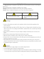
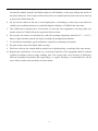
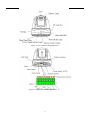
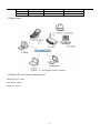
1
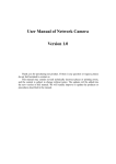
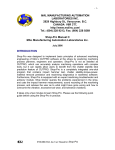
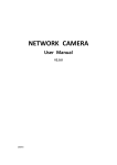
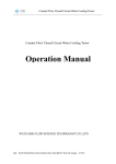
User Manual of Cost-effective Network Camera
Version 1.0
Thank you for purchasing our product. If there is any question or request, please do
not feel hesitated to contact us or our dealer.
This manual may contain several technical incorrect places or printing errors,
and the content is subject to change without notice. The updates will be added to the
new version of this manual. We will readily improve or update the products or
procedures described in the manual.
Safety Instruction
These instructions are intended to ensure that user can use the product correctly to avoid danger or
property loss.
The precaution measure is divided into “Warnings” and “Cautions”.
Warnings: Serious injury or death may cause if any of the warnings is neglected.
Cautions: Injury or equipment damage may cause if any of the cautions is neglected.
Warnings Follow these safeguards to Cautions Follow these precautions to
prevent serious injury or death.
prevent potential injury or material
damage.
Warnings:
1. In the use of the product, you must be strict compliance with the electrical safety regulations of the
nation and region.
2. Input voltage should meet both the SELV (Safety Extra Low Voltage) and the Limited Power Source
with AC 24V or DC 12V according to the IEC60950-1 standard. Please refer to technical specifications
for more details.
3. Do not connect several devices to one power adapter as adapter overload may cause over-heat or fire
hazard.
4. Please make sure that the plug is firmly inserted into the power socket.
5. When the product is installed on wall or ceiling, the device shall be firmly fixed.
6. If smoke, odor or noise rise from the device, turn off the power at once and unplug the power cable, and
then please contact the service center.
7. If the product does not work properly, please contact your dealer or the nearest service center. Never
attempt to disassemble the camera yourself. (We shall not assume any responsibility for problems caused
by unauthorized repair or maintenance.)
Cautions:
1.
Make sure the power supply voltage is correct before using the camera.
2.
Do not drop the camera or subject it to physical shock.
3.
Do not touch CMOS (Complementary Metal-Oxide Semiconductor) modules with fingers. If cleaning
is necessary, Please use dry and soft cloth for outside panels cleaning. For persistent smudges, use soft
3
cloth with a bit of cleaning agent, wipe it gently and dry it after all the above operations. Volatile
solvents like ethanol, benzene and dilution agent are all forbidden, or they may damage the surface of
the panels otherwise. If the camera will not be used for an extended period, please turn on the lens cap
to protect the CMOS from dirt.
4.
Do not aim the camera at the sun or extra bright places. A blooming or smear may occur otherwise
(which is not a malfunction however), and affecting the endurance of CMOS at the same time.
5.
The CMOS may be burned out by a laser beam, so when any laser equipment is on using, make sure
that the surface of CMOS will not be exposed to the laser beam.
6.
Do not place the camera in extremely hot, cold (the operating temperature shall be-10℃~+60℃ ),
dusty or damp locations, and do not expose it to high electromagnetism radiation.
7.
To avoid heat accumulation, good ventilation is required for operating environment.
8.
Keep the camera away from liquid while on using.
9.
While on a delivery, the camera shall be packed in its original packing, or packing of the same texture.
10. Regular part replacement: a few parts (e.g. electrolytic capacitor) of the equipment shall be replaced
regularly according to their average enduring time. The average time varies because of differences
between operating environment and using history, so regular checking is recommended for all the
users. Please contact with your dealer for more details.
4
Index
CHAPTER 1
INTRODUCTION..............................................................................................................................................6
PRODUCT INTRODUCTION .............................................................................................................................................................6
1.1 APPEARANCE INTRODUCTION..................................................................................................................................................6
1.2 STATE INDICATE LAMP INTRODUCTION ...................................................................................................................................8
1.3 APPLICATION ...........................................................................................................................................................................9
1.4 DEFAULT IP, USER NAME AND PASSWORD ...............................................................................................................................9
CHAPTER 2
INSTALLATION..............................................................................................................................................10
2.1 NOTICE OPTIONS ...................................................................................................................................................................10
2.2 INSTALLATION STEP ..............................................................................................................................................................10
2.3 ALARM OUTPUT CONNECTION ...............................................................................................................................................12
2.4 PRESSED-LINE TERMINAL INTRODUCTION ............................................................................................................................12
CHAPTER 3
PARAMETER CONFIGURATION...............................................................................................................13
3.1 NETWORK CAMERA CONFIGURATION....................................................................................................................................13
3.1.1 Wireless Network Camera(Only support –W series) ....................................................................................................13
3.1.2 Cable Network ..............................................................................................................................................................14
3.2 SET PARAMETERS THROUGH IE .............................................................................................................................................14
3.3 PARAMETER CONFIGURATION THROUGH CLIENT SOFTWARE .................................................................................................17
3.4 SEARCH AND AMEND IP ........................................................................................................................................................22
3.5 IP CAMERA ACCESS WAN.....................................................................................................................................................23
3.5.1 Dial up with PPPoE.......................................................................................................................................................24
3.5.2 WAN Access..................................................................................................................................................................24
3.6WIRELESS IP CAMERA ACCESS ..............................................................................................................................................26
CHAPTER 4
MENU INTRODUCTION...............................................................................................................................29
4.1 MENU TREE ILLUSTRATION ...................................................................................................................................................29
4.2 MAIN MENU FUNCTION INTRODUCTION ...............................................................................................................................30
4.2.1 Motion...........................................................................................................................................................................30
4.2.2 Preset.............................................................................................................................................................................30
4.2.3 Defense .........................................................................................................................................................................30
4.2.4 Privacy Protect ..............................................................................................................................................................30
4.2.5 Alarm setting .................................................................................................................................................................30
4.2.6 Clear..............................................................................................................................................................................30
4.2.7 Password .......................................................................................................................................................................30
APPENDIX 1
PIN DEFINITION ..........................................................................................................................................32
APPENDIX 2
PORT MAP .....................................................................................................................................................33
APPENDIX 3
TECHNOLOGY SPECIFICATION .............................................................................................................35
5
Chapter 1
Introduction
Product Introduction
DS-2CD726F-PT, DS-2CD727PF-PT DS-2CD728PF-PT series cost-effective cameras are widely
applied in house and medium enterprises indoor surveillance. The features are as following:
z
Adopted High Performance TI DSP chip;
z
Introduced H.264 video compression technology, which provides high compression ratio and flexible
processing.
z
Ample Function: Heartbeat, PT control, Voice Talk, Alarm, User Management;
z
Network Function: Support the complete TCP/IP protocols, video/alarm/audio data and IE browsing.
z
Minimum Illumination up to 0.4Lux/F1.2(0Lux with IR);
z
High Signal /Noise Ratio;
z
A high degree of color reduction;
z
Embedded P/T, realizes Pan and Tilt rotation;
z
Built-In IR, supports Day and Night surveillance
z
Supports Infrared Remote Control;
z
Support s SD Card for Local Recording.
z
Supports Privacy Protect, easily realized through Remote Control;
z
Power Supply: DC12V±10%
[Notice] IR, wireless, alarming, audio, SD card and embedded P/T are optional.
1.1 Appearance Introduction
[Notice]
The following example is DS-2CD727PF-PT.
6
Figure 1-2-1 Forward Looking Appearance
Figure1-2-2 Rearview Interface Appearance
7
Fig1-2-3 Remote Control Panel Introduction
Menu: Press the button for 3 seconds, you will see the camera main menu;
Up:
Control the cursor upwards on the menu state; Control the camera upwards while exit the menu.
Down: Control the cursor downwards on the menu state; Control the camera downwards while exit the
menu.
Left: Control the camera move to the left;
Right: Control the cursor move to the right;
On Guard: Enable the “On Guard” function, and you can deploy the camera through the network.
Cancel Guard: Cancel “On Guard” deployment and you cannot set the “On Guard” through the network.
[Notice] When the Menu is Open, the above mentioned “Security” and “Withdraw” are separately
used as “IRIS+” and “IRIS-”. The function of “F1, F2, F3, F4 and ” is temporarily reserved. You
can control the camera rotation with the Remote Control. Once the direction button is pressed, the
camera will gyrate towards the orientation you select. It will not stop until you press the “Menu”
button.
1.2 State Indicate Lamp Introduction
Alarm
×
×
×
×
√
On Guard
×
×
√
√
×
Privacy Protect
×
√
×
√
×
8
State Indicate Lamp
Off
Green On
Red On
Orange On
Red Flicker(1 /s)
√
√
√
×
√
√
√
×
√
1.3 Application
Figure 1-3-1 Topological Graph of System
1.4 Default IP, User Name and Password
Default IP: 192.0.0.64
User Name: admin
Password: 12345
9
Green Flicker(2/s)
Red Flicker(2 /s)
Orange Flicker(2/s)
Chapter 2
Installation
2.1 Notice Options
1. Please check if all the items on the package list have been included with your camera.
2. Read the following contents carefully before installation.
3. Make sure that all the related equipment is power-off during installation.
4. Check the power supply to prevent any damage caused by un-matching problems.
5. This product is not for any environment of high humidity or high temperature. Conditions of rain,
airlessness or frequent shaking are also prohibited.
6. Never install the camera nearby venthole of the air conditioning, or the lens will be dewed, which
results in mistiness.
7. If the product does not operate properly, please contact your dealer or the nearest service center.
Never attempt to disassemble the camera yourself. Users are responsible for any problem caused
by modification or repairing without authorization.
2.2 Installation Step
Both DS-2CD726F-PT、DS-2CD727PF-PT and DS-2CD728PF-PT adopt the following installation
method, the example is DS-2CD727PF-PT.
Step 1: Take out the metal fixed plate, and install it on the wall or ceiling with the bolt.
Step 2: Put the slot (on the camera’s pedestal) into the socket (on the metal fixed plate), and gently push it
back, till it is fixed. The above introduce is as shown in the Figure2-2-1.
10
Figure 2-2-1 Schematic Installation
[Notice]
If you need to take the camera down from the metal fixed plate after installation, never
forcedly pull or draw it. You can press the small metal sheet popped out on the bottom of metal fixed
plate, and make it leave the small socket. Hold down the pedestal and slowly push it forward to
remove the camera.
11
2.3 Alarm output Connection
There are two on/off alarm inputs and one on/off alarm output. The following figure gives you visual
illustration.
Figure 2-3-1 Alarm output Connection
The alarm output is a on/off output that requires external power supply on connection. The external
direct current supply shall not be beyond 12V DC/30mA. Use alternating-current main, please attach the
relay. Equipment damage or electric shock may cause without relay.
2.4 Pressed-Line Terminal Introduction
Figure 2-4-1 Pressed-Line Terminal
Connect the external alarm input, output and RS-485 control line, please gently press the orange
Pressed-Line Terminal and Plug the line into the connection hole, then release the Pressed-Line Terminal.
[Notice] Gently draw the line to make sure the line is firmly connected, which avoid the open circuit
and out of control.
12
Chapter 3
Parameter Configuration
There are several network parameters of the camera that need to be set after the hardware installation.
Those parameters including IP address, subnet mask and port number, etc. can be set through various
kinds of methods, 2 of which are introduced as below.
1. Set the camera parameters such as IP address and PPPOE through IE.
2. Set the camera parameters through the client software.
Please make sure that the PC and network camera are connected and can ping successfully before the
parameter setting.
3.1 Network Camera Configuration
3.1.1 Wireless Network Camera(Only support –W series)
Type 1: Point to Point Connection Mode
In the mode, IP camera directly links to the wireless network laptop. It’s shown as following figure:
[Notice] The above-mentioned function is reserved at present.
13
Type 2: Integration Connection Mode
In the mode, the IP camera links to wireless accessing station firstly. The following figure illustrates
this:
3.1.2 Cable Network
Type 1: Trough the Ethernet interface access LAN
In this mode, the IP camera accesses the LAN trough the switch or the hub.
As the following figure show:
Type 2: Trough the Router access WAN
User can visit the IP camera on the Internet. Broad band router requests IP Masquerade., i.e., visual
sever.
3.2 Set Parameters through IE
[Notice] Before watch the camera video through web browser, user should set the security level.
Open the web browser, and enter the menu “Tool/ internet option/Security/Custom level”, then set
14
the security level to Security Level –Low, or enable ActiveX Control and the Plug-in directly. Figure
3-2-1 gives you a visual illustration. After you can see the camera video, set the security level to the
default level for security.
Figure 3-2-1 Set the Security Level
The default IP of the camera is 192.0.0.64 with 8000 as the default port, admin as the administrator,
and 12345 as the password. The administrator can create up to 15 separate operators with different right
levels.
To login the camera through IE, input the IP address in the address column, and the “Login” dialog
box will pop-up as Fig. 3-2-2. Input your user name and password, and then click “Login” to enter the
“preview” page. Double click the “Camera 01” channel or “Preview” button to view the menu as Figure
3-2-3. Right click the “Camera 01” channel, and the “Main Stream”, “Sub Stream” and “Open sound”
options will popup. Select the Open sound option.
15
Fig. 3-2-2 Login Interface
Fig 3 -2-3 Previewing Interface
The “Playback” and “Log” functions can be used only in the condition of existing the SD card. To set
the camera parameters through IE browser, click “Config” and wait for the “Remote Parameters Config”
dialog box to pop up, and then set the parameters like IP address, etc. for your demand as Fig. 3-2-4.
Enter the menu by invoking the 95th pre-set. Select the function you want by clicking the direction key.
Click the IRIS+ button you can enter the submenu. The menu operation is like the remote control.
[Notice] If plug the SD card into the camera, user should enter the “config” and select “other
function” to format the SD card.
For more specific information of “Remote Parameters Config”, please refer to “Instructions of Client
16
Software (version 4.01)” from Section 2.5.3 of remote-distance parameter settings. Instructions can be
found in the client software4.01 in the path of “Start” → “Program”→ “client software 4.01” after
installation.
Fig. 3-2-4
Remote
Parameters Config
3.3 Parameter Configuration through Client Software
After the installation of client software 4.01, click the “client software 4.01” in “Start”→
“Program”→ “client software 4.01”, a message box of “Register Administrator” as Fig. 3-3-1 will appear
by then for the first time running. Both the user name and password should be no less than 6 digits for
registration.
[Notice]
Please keep the user name and password in mind .You may not be able to get access to the
software if any of them is missing.
17
Fig.3-3-1 Register Administrator
Enter the registered user name and password as Fig. 3-3-2. Click “Login” to enter the “Preview”
menu as Fig. 3-3-2.
Fig. 3-3-2 User Login
Fig. 3-3-3 Preview Menu
Click the “Configure” button in Fig. 3-3-4, and then right click the blank spaces in the middle. Click
the “Create Root Node” button as Fig. 3-3-4, and the “Area Properties” message will pop up as fig 3-3-5.
18
Fig. 3-3-4Create Root Node
Fig. 3-3-5Area Properties
Input the area name (you can create whatever name you like) and click “OK” as Fig. 3-3-5. Then right
click the area name you have just created as Fig. 3-3-7.
19
Fig. 3-3-6Area Name Adding Completed
Fig. 3-3-7Right Click the Area Name
Click “Add Device”, and the “Server Properties” dialog box will pop up as Fig. 3-3-8. Input your
“Server Name” and select “HC” from the “Server Type” option. Select “Normal” from “Register” option.
Input your camera IP in “Server IP”, e.g. 192.0.0.64; “User Name”: admin, “Password”: 12345, and 8000
for the default “Port”, and then modify “Channel” to 1. Click the “OK” button as Fig. 3-3-8.
20
Fig. 3-3-8Add Device
Fig.3-3-9 Camera Adding Completed
Click the “Preview” button to enter the “Preview” menu as Fig. 3-3-10. Double click the channel
name in the left tree to preview the pictures.
21
Double click the channel
Fig.3-3-10Preview Menu
Please refer to “Network Video Surveillance Software Operation Instruction (4.01)” for more detailed
parameters configuration. You can find the document in PC Operating System after the installation of
client software 4.01 by selecting “Start”-> “Program”-> “client software 4.01”.
3.4 Search and Amend IP
Run the software of SADP in the CD-ROM attached in the camera, and click the “enter” to enter the
list which displays the online device’s information, such as IP address, port, subnet mask, device
serial-number and so on. It’s shown as following:
22
Fig.3-4-1 Search IP Tool
Input the Password (default password12345), and click “modify”, then you can modify the device’s IP
address, port and subnet mask. The following fig. gives illustration:
Fig.3-4-2 Modify Device Information
3.5 IP Camera Access WAN
IP camera supports WAN access based on PPPoE dial up function..
23
3.5.1 Dial up with PPPoE
Make sure that the user name and password of PPPoE are set correctly by the client software (refer to
“User Manual of Network Digital Surveillance Software”) as Fig.3-5-1. The camera will try to establish
connection to the network with PPPoE function automatically every time when it is powered on, and get a
dynamic IP address by then.
Fig. 3-5-1 Dial Up with PPPoE
[Notice] Please make sure that the ADSL Modem is powered on .The camera needs to be restarted to
establish the network connection after the configuration of PPPoE parameters for the first time. And
DS-2CD852F do not support this function.
3.5.2 WAN Access
There are two methods to get the access, which are shown as below.
1. Get a static IP from your ISP for WAN access.
You can open some ports (such as 80 & 8000 ports) in the router which has got static IP from the
ISP, and then connect them to the router. After that you can use the client software to control it. Turn to
24
ch3.2 to find the client software operations.
2. Use DNS service for WAN access.
You will need a PC connected to Internet with static IP that owns software providing DNS service at the
same time(such as IP Server)(the PC is so-called DNS server).You can also register a domain name
through the DNS service dealer and visit it with the domain name.
When network camera is connected to WAN with PPPoE, it will get an IP address, and send its name and
the IP to the DNS server. The client software will immediately connect to the PC that used as the DNS
server to tell it which network camera is waiting for access. Then the server will search for all the
registered network cameras, and match the camera with this IP. When the IP address is returned, the
client software will connect to the network camera to get the video.
Operations: Run the client software 4.01, select “Configure”Æ “Server Configuration” select
network camera.
In the right tree, input “Server Name” & “DNS Host IP” in the “Server Configuration” box as Fig
4.1, and click “Confirm”. Select “Configure”-> “Device Management”, double click the network
camera name you just added, the “server attribute” message box will pop up as Fig. 3-5-2. Make sure
that the “sever name” is consist with the sever name in “remote config”; and select “private DNS” in
“register mode”;
then input the IP address of DNS server in “DNS address”, click “Confirm”. Then
you can preview the picture in the “preview” menu.
25
Fig.3-5-2 DNS Server
3.6Wireless IP Camera Access
[Notice] The following message only introduces the –W series wireless IP camera. Take the IE
Browser Access for example.
Before configure parameters of the wireless IP camera, you should set the wireless router. The
following example is TP-LINK. Firstly configure the “network parameter” of the “LAN setting” and
“WAN setting” in the wireless router’s management page. Enter the “Wireless Parameter”, and set the
“SSID NO.”, “Frequency band” and “Mode”. User can input any letter and number in the “SSID NO.” ;
“Frequency Band” is selected according to the on-the-spot environment, and usually we recommend
6
frequency band; Select the “54Mbps(802.11g)”. Select the “Enable Wireless Function” and “Allow SSID
Broadcast”.
User can select “Enable Security Function” according to the on-the-spot environment. You can
select the “Security Type”, “Security Option”, “Key Mode Option” and “Key Content”. Please refer to the
introduction of the wireless router to get the detailed configuration. As shown:
26
Fig.3-6-1 Router wireless parameter configuration
There are two network cards in the wireless IP camera: cable network card and wireless network card.
The default IP of the cable network card is 192.0.0.64 with 8000 as the default port, admin as the
administrator, and 12345 as the password. The wireless network card’s default IP is 192.168.1.64.
User should configure the parameters of the wireless network card through the cable network
interface. The way of visiting is the same as the chapter 3.2. Enter the menu as “Fig. 3-2-2 preview page”
shows, then click the “Config” option, enter the interface as following:
27
Fig.3-6-2 Remote Configure parameter
In channel configuration, you can click WIFI configuration button to set WIFI parameter of wireless
camera. SSID should be same as the wireless router. If your wireless router has a security code, please
enable network key and type into the code.
Net configuration in the picture is the wireless NIC IP address, please set it and pay attention that
wireless IP address and IP camera wired IP address should be in different segment.
28
Chapter 4
Menu Introduction
4.1 Menu Tree Illustration
Fig. 4-4-1 Menu Tree
Trough pressing the “menu” button three seconds or double clicking the 95th pre-set, User will enter
the menu. Move the cursor to the menu you want to select by the “UP” and “DOWN” direction button, and
press the “IRIS+”, User will enable the function. IF the current menu has submenu, you will enter the
submenu through the above mentioned operation. You can also enable the function and enter the submenu
using “IRIS+” in the client software or IE browser. Fig.4-4-1 shows all menu item.
29
4.2 Main Menu Function Introduction
4.2.1 Motion
This camera possesses automatic scan, random scan, frame scan, preset, patrol and pattern and so on.
Select one mode, quit the menu, if the camera don’t receive the control signal within set up automatic
waiting time, it will run in accordance with the selected motion mode.
4.2.2 Preset
Set up the presets which consist of patrol path and contain preset name and lens azimuth.
4.2.3 Defense
This function is linked client software’s alarm parameter. User can enable the deployment and the
linkage mode.
4.2.4 Privacy Protect
When exit the menu and press the “Privacy Protect” on the remote control, user can’t see the camera
video through the client or the IE browser. Press the button again to unchain the protection.
[Notice]
This function can be realized only through the remote control. If you select the video
upload or the alarm upload “on”, even if enable the “Privacy Protect”, you can also see the popped
out video when the camera receives the alarm signal.
4.2.5 Alarm setting
User can set “Alarm Contact”, “Alarm Switch Time”, “Alarm Priority” and response action and so on.
“Alarm Action” has the “Auto Scan”, “Frame Scan”, “Random Scan” , “Patrol path” and so on optional
item.
4.2.6 Clear
Clear the information of preset, patrol scan and other settings.
4.2.7 Password
[Notice] The function is reserved currently.
30
31
APPENDIX 1
PIN DEFINITION
(1)UTP between the network port of camera and HUB (Direct Cable)
(2)UTP between the network port of camera and PC (Cross Cable):
32
APPENDIX 2
PORT MAP
[Notice] The following setting is about TP-LINK router (TL-R410), which is maybe distinct from
other router’s setting.
1. Firstly, select the router’s WAN connection Type. As the following Fig. shows:
2. Set the “network parameter” of the router as the below figure. The setting includes subnet mask and
gateway.
3. Set the port map in the virtual severs of Forwarding. The following figure gives the illustration. One
camera’s ports are 80 and 8000, and its IP address is 192.168.1.23. The other camera’s ports are 81 and
8001, and IP is 192.168.1.24. Afterwards, enable all or TCP protocols. Enable the port map after
pressing the ‘Save’.
33
As the above mentioned setting, we map the router’s port 80 and 8000 to the network camera
192.168.1.23; and port 81 and 8001 to the network camera 192.168.1.24. In this way, user can visit the
192.168.1.23 through visiting the router’s port 80 and 8000.
[Notice]
The port of the network camera cannot conflict with other ports. For example, some
router’s web management port is 80. User can amend the router’s or the camera’s port to solve this
problem.
34
APPENDIX 3
Parameter
Model
TECHNOLOGY SPECIFICATION
DS-2CD726F-PT
DS-2CD727PF-PT
DS-2CD728PF-PT
Image Sensor
1/4 inch CMOS
1/3 inch SONY Super HAD CCD
Effective Pixels
640 (H) × 480 (V)
500 (H) × 582 (V)
Camera
Lens mount
M12×0.5
Lens
3.6mm
Min. Illumination
0.4Lux @ F1.2
0.1Lux @ F1.2 (0 Lux with IR)
Infrared Function
---
Support
Video Output
Test Monitor OUT 1Vp-p Composite Output (75Ω/BNC)
752 (H) × 582 (V)
Compression standard
Video Compression
H.264
Video Output
32 K ~ 2M, adjustable (8Mbps maximum)
Audio Compression
OggVorbis
Image
Image Resolution
704 × 576, 640 × 480, 528 × 384, 704 × 288, 352 × 288, 176 × 144
Frame Rate
25fps (704 × 576)
Function
Horizontal Speed
Pan: 0-170°;
Tilt: 0-90°
0.3 ~ 20°/s(adjustable)
Vertical Speed
0.3 ~ 20°/s(adjustable)
Pan and Tilt Preset Speed
20°/s
RS-485 Protocols
HIKVISION, PELCO-P/D (addible)
Scan Mode
Cameras controlled by the client software or remote control can scan ≤170°range
Number of Preset
200
Pan and Tilt Range
Privacy Protection
Prevent Previewing through Network, just Preview on the Monitor.
Menu Language
Chinese and English, 10 characters
Mouse Control
Support Mouse Drag while select HIKVISION protocol in Client Software
Motion Detect
Support
Dual Stream
Support
SD Card Local Recording
Support
Heartbeat
Support
Password Protection
Protocols
Interface
Support
TCP / IP, HTTP, DHCP, DNS, RTP / RTCP, PPPoE (FTP, SMTP, NTP, SNMP addible)
Voice Input
2channels ,1 channel 3.5mm audio interface (2.0 ~ 2.4Vp-p,1kΩ) and MIC internal channel.
Voice Output
1 channel 3.5mm audio interface (Line level, 600Ω)
Communication
1 RJ45 10M / 100M self-adaptive Ethernet port , 1 RS-485 interface (802.11g WLAN
option, IR Remoter option)
Alarm Input
2 channels signal input
Alarm Output
1 channel relay output
35
Others
Working Temperature
-10℃ ~ 60℃
Power Supply
12V DC, ±10%
Power Consumption
9W MAX
Dimension(mm)
φ125 × 136.5
Weight
450g
36