1
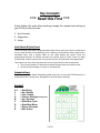
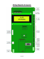
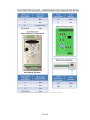
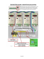
ECHO REACTION
Standard Version
Version 3.30
(For use with the WIC ECHO Controller Hardware)
USER’S MANUAL
1 of 33
Table of Contents
Description
Page
Updates & New Features.................................................................................................... 4
Key Concepts....................................................................................................................... 5
Terms & Definitions: ........................................................................................................... 6
External Switch Definitions ................................................................................................. 7
Diagnostics .......................................................................................................................... 9
Keypad test ..................................................................................................................... 9
Solenoids......................................................................................................................... 9
Input Switches (Sensors) .............................................................................................. 10
Motor & Motion Test ................................................................................................... 10
Set-Up ............................................................................................................................... 11
System Set-Up ............................................................................................................... 12
ECHO Name (for use with Wireless Accumulator).................................................. 12
Date / Clock (used for Time-Based Auto Start)....................................................... 12
Network Mask (for use with Wireless Accumulator).............................................. 13
Pass-code .................................................................................................................. 13
Reboot Controller..................................................................................................... 14
Motor Set-Up................................................................................................................. 15
Watering & Load/Unload Speeds (for use with Variable Speed Motors).............. 15
VFD Setup (for use with Variable Speed Motors) ................................................... 16
ECHO Settings................................................................................................................ 18
Basket (Hook) Counts & Cycle Counts ..................................................................... 19
Water Duration ........................................................................................................ 19
Schedule (Time Based Automatic Run) ................................................................... 20
Switch De-bounce Times.......................................................................................... 21
Operations (Water Mode) ................................................................................................ 23
STEP/STOP/WATER....................................................................................................... 24
CONTINUOUS RUN MODE............................................................................................ 25
ALL ON (SPRAY CONTINUOUSLY) ................................................................................. 26
LOAD/UNLOAD ............................................................................................................. 27
Wiring Diagrams & Layouts: ............................................................................................. 29
2 of 33
Cherry Creek Systems
2675 Akers Drive
Colorado Springs, CO 80922
Toll Free 877-558-3246
877
www.cherrycreeksystems.com
[email protected]
Dear Customer:
We would like to thank you for taking a bold step in greenhouse irrigation automation
by purchasing our ECHO REACTION control system! Although it might appear to be very
complex, the greatest possible care went into making this program as user friendly as
possible while keeping all the functionality that you have come to expect.
There have been many changes
ges to the new REACTION program we designed for the WIC
Controller.
roller. We believe that once you become familiar with all that this new program has
to offer, you will be pleased with how eas
easy managing & irrigating your hanging crops
has become.
We would welcome and encourage you to make suggestions as to how we can improve
this User’s Manual.
anual. It is our intent to provide you with the highest quality equipment
and state-of-the-art
art watering systems, as well as first rate tech
technical
al follow up & support.
If this is the 1st time setting up the ECHO REACTION Controller, please follow this order
in working through the manual:
1. Key Concepts
2. Diagnostics
3. Setup
Again, thank you for your business and we look forward to assisting you in any way we
can. Feel
eel free to give us a call, or contact us via email (see above).
Sincerely,
Cherry Creek Systems Team
3 of 33
Updates & New Features
ECHO REACTION – 3.30 Standard Version – “WIC ECHO”
Time Zone Scheduling:
You now have the option of setting a scheduled start time and run intervals
for the ECHO watering programs. Example: User sets the ECHO to start on
July 4th at 7AM, and run 1 time every 3 days.
Easy User Interface:
Operator programming and setup is done via the keypad and LCD display.
All settings programmed using a menu function similar to the CCS Boom
controllers, allowing for much more flexibility.
Multiple Watering Modes:
Watering Modes include Step/Stop/Water, S/S/W & Leach, Continuous, and
Spray Cycle (for spraying pesticides, chemicals, etc.).
Per Layer Watering Times:
Watering times can be set differently per layer, making it easier to control
different size baskets per layer on an ECHO system. Commonly the ECHO is
used to grow 10” basket on the upper tier the 12” basket in the lower tier.
Load & Unload Speeds:
Load and Unload speeds can be set so they are don’t affect the Watering
speeds (set apart from each other)
Hook Counting Switch:
Using Hook Count to know the Cycle’s start &stop points; for more
flexibility in the watering modes and better efficiency loading & unloading.
Diagnostic Menu:
Has a full Diagnostics menu for help when troubleshooting the system or
testing switches.
Remote Environmental Control Start:
Remote Start function allows for a signal from the Environmental Controls
to initiate the ECHO program as prompted by the systems specific irrigation
module allotted for the ECHO.
EZ WIC Download Device:
The Standard can be upgraded to the Elite easily by using the CCS EZ WIC
Download device.
4 of 33
Key Concepts
*** Read this First ***
Please follow this order when working through the manual and setting up
your ECHO for the first time:
1. Key Concepts
2. Diagnostics
3. Setup
Hook Count & Cycle Count:
The ECHO REACTION uses a programmable Hook Count and Cycle Count to determine
the run time duration of the watering cycle. Hooks are counted by a switch input that is
activated every time a basket hook on the cable passes the switch. Once the
programmed amount of baskets activates the switch, one (1) Cycle Count has been
incremented, and the system will run only the amount of Cycles that are programmed.
Two events can occur that will cause the current Cycle Count to be incremented:
1. The current number of Hooks encountered reaches the pre-set Hook count.
2. An End-of-Cycle hanger or marker is encountered.
Scheduled Start:
The Automatic Time Based Scheduling allows the user to start the ECHO based on a
programmed start & stop time, being able to set both hours and days.
Keypad:
0-9
0
1
A
B
C
D
F
E
= Data Entry
= No / Disable
= Yes / Enable
= Change Settings (during run)
= Up / Increase
= Start/Stop Cycle
= Start/Stop Motor
= Down / Decrease
= Exit & Save
5 of 33
Terms & Definitions:
Step/Stop/Water: * Suggested for drenching, heavy feeding, or run-thru watering *
When this operation is used the controller will run the motor until the activator tab
switches are activated at which time the motor is stopped and the basket is watered for
the programmed water time. When watering is complete, the motor is started again.
Because the motor stops and stops for every basket during this watering operation, the
total run (watering) time can take longer and cause more wear and tear on the system if
used as the common watering method. (Leach can be used with Step/Stop/Water)
* For Heavy Saturation of the basket, use the Continuous Run Mode and program
multiple Cycle Counts – the results are similar to Boom watering – even saturation
throughout the media but not over watered, draining-thru, or dripping on the aisles or
plants below.
Continuous Run Mode: * Suggested for everyday use *
When this operation is used the controller will continuously run the motor and water
baskets as they pass by and trip the activator tab switches. Because the motor does not
stop for a watering operation, the program is completed sooner and there is less wear
and tear on the system. (Leach delay does not apply)
Spray Continuously (All On):
When this operation is used the controller will simultaneously run the motor and
activate the upper and lower solenoids of the watering station, not stopping until the
Hook Count or End of Cycle is met.
Water Duration:
This value is used to determine the amount of time that water solenoid will be activated
when a basket has entered a watering station. Different Values can be assigned to both
the upper and lower watering solenoids.
Leach Time:
This value is used to determine the amount of time after watering, that a basket will
remain in the watering station to leach (drain). When using Step/Stop/Water mode
with Leach, a basket will not be cleared from the station until the Leach time has
elapsed. The same value is used for both the upper and lower watering stations.
Acceleration:
Setting that controls how long it takes the motor to get up to speed when starting (only
for use with Variable Speed motor set-ups)
VFD: (Variable Frequency Drive)
Used to power the variable speed 3 Phase AC gearmotors that turn the ECHOs drive
drum.
6 of 33
External Switch Definitions
7 of 33
Main Menu:
* To get to the Main Menu from almost
any screen, press “E” repeatedly *
ECHO NAME
02:16:01
ECHO – W3.30
1= WATER MODE
2= SETUP
3= DIAGS
If it is the first time setting up the
ECHO, it is highly recommended that
you go through the diagnostic menu,
BEFORE YOU SET UP YOUR ECHO.
This process will insure all the inputs
are functioning properly; nothing
was damaged during shipping.
8 of 33
Diagnostics
* The best way to get thru the Diagnostics process is to work backwards through the
menu. Starting with the Keypad test, and ending with the Motor & Motion tests. *
* To get to the Main Menu from almost any screen, press “E” repeatedly *
1. From Main menu press 3 (DIAGS)
Diagnostics Menu:
DIAG MENU
E = EXIT
1=MOTOR & MOTION
2=SWITCHES/SOLENOIDS
4=KEYPAD
* Selection Item 3 is NOT used for ECHO or ECHO3 *
Quick Menu/
Keypad Number
Reference
Keypad test
(Main Menu, Press 3, Press 4)
1. From Main menu press 3 (DIAGS)
2. From the Diagnostics menu press 4 (KEYPAD):
KEYPAD TEST E=EXIT
KEY =
3. Press any keys on the keypad to see them displayed on the screen.
4. Press the “E” key repeatedly to return to Main menu.
Solenoids
(Main, 3, 2, 1)
1. From the Main menu press 3 (DIAGS)
2. From the Diagnostics menu press 2 (SWITCHES/SOLENOIDS):
3. Press “1” to go to the Solenoid Test screen: (next page)
9 of 33
SOLENOID TEST E=EXIT
SOL
1 2 3 4 5 6 7 8
SOL = 1 0 0 0 1 0 0 0
SOL 1 = ROWS 01
4. Press the “1” through “8” keys to alternately turn on and off the respective
solenoid valves; water should appear as the keys are pressed.
5. Press the “E” key repeatedly to return to the Main Menu.
Input Switches (Sensors)
(Main, 3, 2, 2)
* In this menu, check to see if the ECHO’s S are working properly. *
Sensors / Switches
1 = Upper Activator
2 = Unused
3 = Lower Activator
4 = Hook Count
5 = Remote Cycle Start
6 = Remote Motor Start
7 = End of Cycle
8 = Tab (Photo Eyes only)
1. From the Main menu press 3
2. From the Diagnostics menu
press 2 (SWITCHES/SOLENOIDS):
3. Press 2 for Input Switches
SWITCH TEST
SW
E=EXIT
1 2 3 4 5 6 7 8
SW = 0 0 0 0 0 0 0 0
MARKER
000 003
4. Press each switch and verify that its value changes.
5. Press the “E” key repeatedly to return to Main menu.
Motor & Motion Test
(Main, 3, 1)
1. From the Main menu press 3 (DIAGS)
2. From the Diagnostics menu press 1 (MOTOR & MOTION):
MOTOR DIAG:
PWR: 10.0%
C=+.5 D= -.5% EXIT=E
B=+10 F= -10%
* NOTE: For AC VFD controllers, if
the power is less than 2.5%, the
motor will NOT be able to start,
and running the motor at less than
15% for any length of time is NOT
recommended and can result in
damage to the motor *
3. Press “B” to increase speed by 10.0% or “C” to increase speed by 0.5%.
4. Press “F” to decrease speed by 10.0% or “D” to decrease speed by 0.5%.
5. Press “E” to stop and Exit back to the Motor & Motion menu
10 of 33
Set-Up
If you are setting up for the first time, please go through your diagnostics
menu first, before proceeding with Setup.
There are 3 items under the SET-UP menu.
1. System Settings
2. ECHO Settings
3. Motor Settings
In this “Set-Up” section, we will start with the System Set-Up and work our way through
the other sections as they apply. This is the easiest way to “Initialize” the Controller.
From the Main Menu press 2 for SETUP MENU
SETUP MENU
E=EXIT
1= SYSTEM SETTINGS
2= ECHO SETTINGS
3= MOTOR
E= EXIT
Press 1 for SYSTEM Settings, the Controller will prompt a Pass-code to be input by the
user. The factory set default Pass-code is 0000 (four Zeros).
* To change the Pass-code, refer to the “Pass-code” section of the “System Set-Up” menu *
ENTER PASS CODE:
E = EXIT
****
SYSTEM SETUP
E= EXIT
1= NAME
2= DATE
3= NETWORK 4= PASSCODE
5= INITIALIZE
11 of 33
System Set-Up
________________________________________________________
ECHO Name (for use with Wireless Accumulator)
(Main, 2, 1, 1)
1.
2.
3.
4.
From Main Menu press 2
From Set-Up Menu press 1 (SYSTEM)
Enter Pass Code (0000 by Default)
From the System Set-up menu press 1 (NAME)
ENTER WIC NAME
NAME: ECHO – 001
S/N: NI060356
ECHO – W3.30 E= SAVE
5. The default name will be the WIC Serial Number.
6. To change, use the “B” & “F” keys to scroll through the characters, and use
the “C” & “D” keys to move to the next character.
7. Press “E” to Save and Exit.
________________________________________________________
Date / Clock (used for Time-Based Auto Start)
(Main, 2, 1, 2)
1.
2.
3.
4.
From Main menu press 2
From Setup menu press 1
Enter Pass Code (0000 by Default)
From the System Set-up menu press 2 (DATE)
SET SYSTEM DATE/TIME
C/D=MOVE 0-9=CHANGE
A=CANCEL
E=SAVE
12/22/2010 04:12:26
5. Using a 24 hour clock (Military time), input the Actual Date/Time using the
“0” through “9” keys. To zero the digits, press the “0” key several times.
Notice the last line of text will change as numbers are entered.
6. Press the “E” to Save the Actual Date/Time & to go to System Set-Up.
12 of 33
________________________________________________________
Network Mask (for use with Wireless Accumulator)
(Main, 2, 1, 3)
1.
2.
3.
4.
From Main menu press 2
From Setup menu press 1
Enter Pass Code (0000 by Default)
From the System Set-up menu press 3 (NETWORK)
SET NETWORK MASK
CURRENT: 255
NEW: 010
0-9, B/F= CHANGE E=SAVE
5. This menu is for setting a “Network Mask” (a value from 1 to 255) that will
identify this particular ECHO to the given Network Accumulator.
Please contact CCS for further details and clarification.
6. Press “E” to Save and Exit.
________________________________________________________
Pass-code
(Main, 2, 1, 4)
1.
2.
3.
4.
Master Pass-code:
8B9A
From Main menu press 2
From Setup menu press 1
Enter Pass Code (0000 by Default)
From System Setup menu press 4 (PASSCODE)
ENTER PASSCODE
NEW: 1234
CURRENT: 0000
F =CANCEL E =SAVE
5. Enter any 4-digit Pass-code and press “E” to Exit & Save.
*** Write the pass-code down on the inside of the cover of this Manual ***
6. Press “E” to Save and Exit.
13 of 33
________________________________________________________
Reboot Controller
(Main, 2, 1, 5)
1.
2.
3.
4.
* Described in the Definitions section *
From Main menu press 2
From Setup menu press 1
Enter Pass Code (0000 by Default)
From System Setup menu press 5 (REBOOT CNTRLR)
-
SOFT RESET
-
1. The Controller will be reset and will return to the Main menu.
14 of 33
Motor Set-Up
________________________________________________________
In this section, the user will go over the Motor Set-Up and work through the
corresponding sections as they apply.
1. From the Main Menu press 2 for SETUP MENU
ENTER SETUP OPTION
1= SYSTEM SETTINGS
2= ECHO SETTINGS
3= MOTOR
E= EXIT
2. Press 3 for MOTOR Setup, the Controller will prompt a Pass-code to be input by
the user. The factory set default Pass-code is 0000.
MOTOR SETUP:
1= WATER/LOAD SPEEDS
2= VFD SETUP
E= EXIT
________________________________________________________
Watering & Load/Unload Speeds (for use with Variable Speed Motors)
(Main, 2, 3, 1)
1.
2.
3.
4.
From Main Menu press 2
From Set-Up Menu press 3 (MOTOR)
Enter Pass Code (0000 by Default)
From the Motor Set-Up menu press 1 (Water/Load Speeds)
MOTOR SETUP
E=EXIT
WATER SPEED:
LOAD SPEED:
15.0%
15.0%
* NOTE: For AC VFD controllers,
if the power is less than 2.5%,
the motor will NOT be able to
start, and running the motor at
less than 15% for any length of
time is NOT recommended and
can result in damage to the
motor *
5. Enter desired Water and load speeds as a percentage of motor power.
Setting this below 15% may cause damage to the motor. Setting this below
2.5% will not allow AC VFD motors to start.
6. To change, use the “0-9” keys to enter the desired percentage of power. The
“B” & “F” keys allow the user to move between the two fields.
7. Press “E” to Save and Exit.
15 of 33
________________________________________________________
VFD Setup (for use with Variable Speed Motors)
(Main, 2, 3, 2)
1.
2.
3.
4.
From Main Menu press 2
From Set-Up Menu press 3 (MOTOR)
Enter Pass Code (0000 by Default)
From the Motor Set-Up menu press 2 (VFD Setup)
SET ACCEL TIME
0-9=DATA B,F=UNITS
E=SAVE
ACCEL: 02.0 SECONDS
5. Set the Acceleration time and press “E” to save and move to the next screen
SET DECEL TIME
0-9=DATA B,F=UNITS
E=SAVE VALID ONLY AC
DECEL: 02.0 SECONDS
6. Set the Deceleration time and press “E” to save and move to the next screen.
*The deceleration time setting has no affect on DC motor drives*
SET S-CURVE VALUE
0-9=DATA B,F=UNITS
E=SAVE VALID ONLY AC
S-CURVE: 00
*The S-Curve setting has no affect on DC motor drives*
7. The S-Curve setting controls the ramp up and ramp down settings for the
ECHO. This setting is used only for AC VFD’s and enables the user to change
the drive’s response. Set the S-Curve Value based on the graph in Figure 3.
(see next page)
8. Press “E” to save and exit to the Motor Setup Screen
9. Press “E” again to Save and go back to the Motor Setup menu.
16 of 33
Figure 1 - S-Curve Example
The thicker line shows the response of the AC drive to both start and stop conditions
assuming that the drive is going from zero to some speed, then back to zero. The
straight lines for ramp up, ramp down, especially at the corners will add a lot of jerk into
the system. Basically, think of it as going from 0FPM to 1000FPM in a fraction of a
second. This is not good for the motor, or the ECHO.
The S-Curve profile that is shown with the thinner line helps to avoid the all at once
acceleration approach. As you can see, the acceleration slowly ramps up from zero, and
ramps down when it gets close to speed. With the GS1/GS2 VFD Controller, we only
have the ability to input the numbers 0-7 for preset S-Curves inside the GS1/GS2
controllers. The higher the number, the more sloped the S-Curve will be. This means
that an S-Curve of 7, will take longer to get to speed, but have a smoother ramp, than an
S-Curve of 2. The same S-Curve is applied to both the acceleration and deceleration of
the ECHO.
NOTE: This setting should be changed from its default (00) if the user notices that the
ECHO is jerky on starting up or stopping. A value of 01 to 04 is the recommended range.
17 of 33
ECHO Settings
________________________________________________________
In this section, the user will go over the ECHO Settings and work through the
corresponding sections as they apply.
From the Main Menu press 2 for SETUP MENU
ENTER SETUP OPTION
1= SYSTEM SETTINGS
2= ECHO SETTINGS
3= MOTOR E=EXIT
Press 2 for ECHO Settings, the Controller will prompt a Pass-code to be input by the
user. The factory-set default Pass-code is 0000 (four Zeros).
*** To change the Pass-code, refer to the “Pass-code” section of the “System SetUp” menu (pg. 19) ***
ENTER PASS CODE:
E = EXIT
****
ECHO Set-Up Screen:
ECHO SETUP
E=EXIT
1=BASKET COUNTS
2=WATER DURATION
3=SCHEDULE
4=SWITCH
18 of 33
________________________________________________________
Basket (Hook) Counts & Cycle Counts
(Main, 2, 2, 1)
* Described in the Definitions section *
1.
2.
3.
4.
From Main Menu press 2
From Set-Up Menu press 2 (ECHO SETTINGS)
Enter Pass Code (0000 by Default)
From the ECHO Set-Up menu press 1 (LENGTH)
HOOK SETUP
E=EXIT
HOOK COUNT: 100
CYCLE COUNT:
1
5. Use the B/F keys to switch between fields and the 0-9 keys to enter data.
6. Enter the Hook Count; this is the number of hooks on the ECHO that will be
watered per cycle (see definition pg.6).
7. Enter the Cycle Count; this is the number of Cycles that the ECHO will run
(see definition pg.6).
________________________________________________________
Water Duration
(Main, 2, 2, 2)
1.
2.
3.
4.
* Described in the Definitions section *
From Main Menu press 2
From Set-Up Menu press 2 (ECHO SETTINGS)
Enter Pass Code (0000 by Default)
From the ECHO Set-Up menu press 2 (WATER DURATION)
UPPER WATER/LEACH
TIMES
E=EXIT
U WATER TIME: 0.0S
U LEACH TIME: 0.0S
5. Use the B/F keys to switch between fields and the 0-9 keys to enter data.
6. Enter the desired values into the appropriate fields for the Upper basket.
7. The Water Time is the amount of time the basket will have water applied
(see definition pg.6).
8. The Leach Time is the amount of time the basket will hang after water is
applied to allow excess water to drip from the basket (see definition pg.6).
9. Once these values are entered, press the E key to move to the Lower basket
settings. (see next page)
19 of 33
LOWER WATER/LEACH
TIMES
E=EXIT
L WATER TIME: 0.0S
L LEACH TIME: 0.0S
1. Enter the desired values into the appropriate fields for the Lower basket.
2. Press “E” to Save & Exit.
________________________________________________________
Schedule (Time Based Automatic Run)
(Main, 2, 2, 3)
* Described in the Definitions section *
1.
2.
3.
4.
From Main Menu press 2
From Set-Up Menu press 2 (ECHO SETTINGS)
Enter Pass Code (0000 by Default)
From the ECHO Set-Up menu press 3 (SCHEDULE)
SET SCHEDULE
E=EXIT
USE SCHDL? NO (1/0)
EVERY: 00HRS 00DAYS
0-9=SET START TIME
5.
6.
7.
8.
To set the Schedule to run, use the 1 key to toggle the input to “YES”.
If the Schedule Function is NOT desired, leave the prompt on “NO”.
Use the B/F keys to switch between fields and the 0-9 keys to enter data.
Set the hour and day fields; this will determine the interval at which the
watering cycle is started (see definition on pg.6).
9. Set the start time, including month, day, year, and all time fields. The start
time is exactly that, the time that the watering cycle will start. After this
time, watering will occur per the hours and days settings.
SET NEXT START TIME
C/D=MOVE 0-9=CHANGE
7/21/12
E=SAVE
11:05:42
10. Press “E” to Save and Exit back to ECHO Setup menu.
20 of 33
________________________________________________________
Switch De-bounce Times
(Main, 2, 2, 4)
1.
2.
3.
4.
* Described in the Definitions section *
From Main Menu press 2
From Set-Up Menu press 2 (ECHO SETTINGS)
Enter Pass Code (0000 by Default)
From the ECHO Set-Up menu press 4 (SWITCHES)
UPPER SWITCH E=NEXT
BASKET ARRIVE/DEPART
SW TIME IN : 00.2S
SW TIME OUT: 01.0S
5. Use the B/F keys to switch between fields and the 0-9 keys to enter data.
6. These settings allow the user to change the switch de-bounce timing for
having a basket arrive and leave the watering area. Essentially, this setting
allows the user an adjustable time to verify that the basket is actually in the
area and has left the area.
7. Adjust Time in and Time out if necessary.
8. Press “E” to move to the next screen.
UPPER SWITCH E=NEXT
1=NORMALLY OPEN **
2=NORMALLY CLOSED
9. Set the type of switch being used by pressing “1” or “2”.
(The ** highlights the current setting)
10. Press “E” to continue and set the same parameters for the Lower Switch.
LOWER SWITCH E=NEXT
BASKET ARRIVE/DEPART
SW TIME IN : 00.2S
SW TIME OUT: 01.0S
11. Set the appropriate parameters and press “E” to continue.
UPPER SWITCH E=NEXT
1=NORMALLY OPEN **
2=NORMALLY CLOSED
21 of 33
12. Set the switch type and Press “E” to continue.
TAB SWITCH E=NEXT
0=UNUSED
1=UPPER HOOKS
2=LOWER HOOKS
13. Set the Tab Switch type using the “0”, “1”, and ”2” keys.
(Tab Switch is not used in most cases)
14. Once the appropriate setting has been selected, press “E” to continue.
TAB SWITCH TIMER
E=EXIT
TIMER: 00.00S
2=LOWER HOOKS
15. Set the Tab Switch Timer.
16. Press “E” to save and exit.
22 of 33
Operations (Water Mode)
In this section, the user will go over the Water Mode Settings and work through the
corresponding sections as they apply.
From the Main Menu press 1 for WATER MODE MENU
SELECT WATER METHOD
1= STEP/STOP
2= CONTINUOUS
3= ALL ON 4=LOAD/UNLD
* NOTE: For AC VFD controllers, if
the power is less than 2.5%, the
motor will NOT be able to start, and
running the motor at less than 15%
for any length of time is NOT
recommended and can result in
damage to the motor *
Step/Stop/Water: * Suggested for drenching, heavy feeding, or run-thru watering *
When this operation is used the controller will run the motor until the activator tab
switches are activated at which time the motor is stopped and the basket is watered for
the programmed water time. When watering is complete, the motor is started again.
Because the motor stops and stops for every basket during this watering operation, the
total run (watering) time can take longer and cause more wear and tear on the system if
used as the common watering method. (Leach can be used with Step/Stop/Water)
* For Heavy Saturation of the basket, use the Continuous Run Mode and program
multiple Cycle Counts – the results are similar to Boom watering – even saturation
throughout the media but not over watered, draining-thru, or dripping on the aisles or
plants below.
Continuous Run Mode: * Suggested for everyday use *
When this operation is used the controller will continuously run the motor and water
baskets as they pass by and trip the activator tab switches. Because the motor does not
stop for a watering operation, the program is completed sooner and there is less wear
and tear on the system. (Leach delay does not apply)
Spray Continuously (All On):
When this operation is used the controller will simultaneously run the motor and
activate the upper and lower solenoids of the watering station, not stopping until the
Hook Count or End of Cycle is met.
Load/Unload:
turns the motor on without activating the water. This is useful for loading and
unloading baskets.
***See below for further details***
23 of 33
_________________________________________________
Quick Menu/
S T EP / S T O P / W A T ER
Keypad Number
Reference
(Main, 1, 1)
1. From the Main Menu press 1 for the WATER MODE MENU
2. Press 1 for Step/Stop watering.
STEP/STOP=MOTOR
STOP FOR WATER&LEACH
1=LOWER
2=UPPER
3=BOTH
E=EXIT
3. Select which hooks to water by pressing 1,2, or 3 on the keypad. For the
following exercise, assume BOTH was selected.
STEP-STOP UPPR/LOWER
C=START/STOP
D=MOTOR ON/OFF
7/21/12
11:11:11
4. Press “C” to start a watering cycle, or “D” to simply start/stop the motor.
Assume that we have selected “C”.
STEP-STOP UPPR/LOWER
BASKET: 1 OF 100
CYCLE : 1 OF 10
START REQ
5. If needed, use the “C” or “E” keys to stop the cycle before it is done.
6. The B/F keys can be used to increase/decrease motor power during the cycle.
7. Watering will continue in the following manner:
a. The first basket will activate the appropriate switches and enter the
watering area, decrementing the basket count.
b. The motor will stop and the basket will be watered for the selected water
time, and will then hang in the watering area for the selected leach time.
c. The motor will turn on and move to the next basket.
d. Baskets will be watered in this manner until the controller counts 100
baskets.
e. After watering the 100th basket, the Cycle counter will increment to 2.
f. Watering will continue until the cycle counter has finished the 10th cycle.
24 of 33
________________________________________________________
CONTINUOUS RUN MODE
(Main, 1, 2)
1. From the Main Menu press 1 for the WATER MODE MENU
2. Press 2 for Continuous watering
CNTINUOUS=MOTOR RUNS
WHILE WATER APPLIED
1=LOWER
2=UPPER
3=BOTH
E=EXIT
3. Select which hooks to water by pressing 1,2, or 3 on the keypad. For the
following exercise, assume BOTH was selected.
CNTINUOUS UPPR/LOWER
C=START/STOP
D=MOTOR ON/OFF
7/21/12
11:11:11
4. Press “C” to start a watering cycle, or “D” to simply start/stop the motor.
Assume that we have selected “C”.
STEP-STOP UPPR/LOWER
BASKET: 1 OF 100
CYCLE : 1 OF 10
START REQ
5. If needed, use the “C” or “E” keys to stop the cycle before it is done.
6. The B/F keys can be used to increase/decrease motor power during the cycle.
7. Watering will continue in the following manner:
a. The first basket will activate the appropriate switches and enter the
watering area, decrementing the basket count.
b. The motor will continue moving and the solenoids will turn on for the
selected water time.
c. When the next basket reaches the watering area, the solenoids will turn
back on again.
d. Baskets will be watered in this manner until the controller counts 100
baskets.
e. After watering the 100th basket, the Cycle counter will increment to 2.
f. Watering will continue until the cycle counter has finished the 10th cycle.
25 of 33
________________________________________________________
ALL ON (SPRAY CONTINUOUSLY)
(Main, 1, 3)
1. From the Main Menu press 1 for the WATER MODE MENU
2. Press 3 for All On watering
SPRAY CONTINUOUSLY
BASKET: 4 OF 100
CYCLE : 1 OF 1
C,D,E = STOP
3. Press “C” to begin watering. Watering will be applied just as in the Continuous
mode for both upper and lower baskets.
SPRAY CONTINUOUSLY
BASKET: 1 OF 100
CYCLE : 1 OF 10
C, E = STOP
4. If needed, use the “C” or “E” keys to stop the cycle before it is done.
5. The B/F keys can be used to increase/decrease motor power during the cycle.
6. Watering will continue in the following manner:
a. Once the motor is started, all solenoids are turned on, and will stay on for
the duration of the cycle.
b. The motor will also stay on for the duration of the cycle.
26 of 33
________________________________________________________
LOAD/UNLOAD
(Main, 1, 4)
1. From the Main Menu press 1 for the WATER MODE MENU
2. Press 4 for Load/Unload
LOAD/UNLOAD BASKETS
C=START/STOP
IDLE
D=MOTOR ON/OFF
7/21/12
11:11:11
3. Press “C” to begin Loading/Unloading baskets.
LOAD/UNLOAD BASKETS
BASKET: 1 OF 100
CYCLE : 1 OF 10
START REQ
4. If needed, use the “C” or “E” keys to stop the cycle before it is done.
5. The B/F keys can be used to increase/decrease motor power by 5%.
6. Water is never applied when using this mode.
27 of 33
TECHNICAL ASSISTANCE: If you have any questions regarding the use of
this program or any other Cherry Creek Systems product, please call:
(719) 380-8373
OR
Toll Free:
(877) 558-3246
Before calling Tech Support, please try resetting the Controller by pressing
the RESET button on the board (shown on the Main Board layout in the
“Wiring Diagrams” section). In most cases, this solves the problem and is
an easy step to perform before calling Tech Support. If the WIC is “lockedup”, this will typically fix it, getting the Controller functional again.
[email protected]
www.cherrycreeksystems.com
28 of 33
Wiring Diagrams & Layouts:
29 of 33
DC Motor Control Board
Fuses F1 and F2 are 8A/250V SLO-BLO 5x20mm.
30 of 33
31 of 33
32 of 33
33 of 33