1
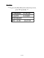
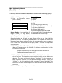
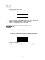
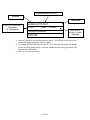
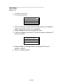
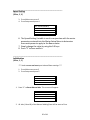
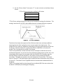
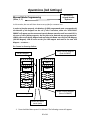
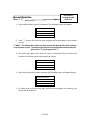
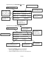
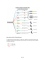
Wireless Irrigation Controller “WIC” Jobbing Version J0.30 USER’S MANUAL 1 of 41 Table of Contents Description Page Updates & New Features for WIC J0.29 ............................................................................. 4 Key Concepts ....................................................................................................................... 5 Terms and Definitions: ........................................................................................................ 7 External Switch Definitions ................................................................................................. 8 Diagnostics ........................................................................................................................ 12 Keypad test .................................................................................................................... 12 Input Switches (Sensors) ............................................................................................... 13 Solenoids ....................................................................................................................... 14 Basic Motor Test............................................................................................................ 14 Encoder Test .................................................................................................................. 15 Walk and Water............................................................................................................. 16 Go To Job ....................................................................................................................... 16 Set-Up ............................................................................................................................... 18 System Set-Up ............................................................................................................... 18 Date / Clock (used for Time-Based Auto Start)......................................................... 18 Pass Mode .................................................................... Error! Bookmark not defined. Speed Setting ............................................................................................................ 20 Initialization............................................................................................................... 20 Motor Set-Up................................................................................................................. 22 Acceleration .............................................................................................................. 23 Drive Settings ............................................................................................................ 24 Timeout (Motion Error timing) ................................................................................. 26 Motor Reversing ....................................................................................................... 27 Encoder Reversing .................................................................................................... 28 Operations (Job Settings) .................................................................................................. 30 Manual Mode Programming ......................................................................................... 30 Manual Mode Run......................................................................................................... 32 Auto Zones (Time Activated Programming) .................................................................. 33 Troubleshooting and Support ........................................................................................... 37 Wiring Diagrams & Layouts: ............................................................................................. 39 Options and Upgrades ...................................................................................................... 41 2 of 41 Cherry Creek Systems 2675 Akers Drive Colorado Springs, CO 80922 Toll Free 877-558-3246 www.cherrycreeksystems.com Dear Customer: We would like to thank you for purchasing our “Magnet Jobbing” program! The greatest possible care went into making this program as user friendly as possible while still keeping all the functionality that you have come to expect. We would welcome and encourage you to make suggestions as to how we can improve this Users Manual. It is our intent to provide you with the highest quality equipment and state-of-the-art watering systems, as well as first rate technical follow up support. If this is the 1st time setting up the Boom, please follow this order in working through the manual: 1. Key Concepts 2. Diagnostics 3. Setup Again, thank you for your business and we look forward to assisting you in any way we can. Feel free to give us a call, or contact us via email (see above). Sincerely, Cherry Creek Systems Team 3 of 41 Updates & New Features for WIC J0.30 Wireless Irrigation Controller – J0.30 “Jobbing” SMART BOOM MOVEMENT: The Boom only moves to the areas that need to be watered & keeps track of the current job magnet position. It no longer has to go from one end of the bay to another (Home to Away, then back to Home) every time it makes one pass and doesn’t have to rest at the “Home” position. This reduces wear and tear on the Boom and its moving parts, saving time and money. WALK & WATER: We have added the possibility to walk beside your Boom and water your crops by the press of a button (optional remote hand-held controller). You can simply walk the Boom to the Area that needs to be watered and turn on and off the solenoid(s). 4 of 41 Key Concepts *** Read this First! *** Please follow this order when working through the manual and setting up your Boom for the first time: 1. Key Concepts 2. Diagnostics 3. Setup The Wireless Irrigation Controller Jobbing Program (hereafter WIC-JOB) was designed to provide flexibility and control while maintaining a simple menu-based programming system. While still sophisticated, the WIC-JOB still attempts to tailor to the grower, especially those comfortable with the previous NIC Jobbing Controller and program. Through the various programmable speeds along with individual solenoid control, the WIC-JOB allows operators to manipulate water usage and time needed when watering crops. The controller’s advanced memory features allow an array of customized options for programming. Growers will find the ease of use and the accuracy of the controller reassuring, as it can be taught to anyone with very little training. The WIC-JOB can hold up to 14 different Time Zones, each containing a specific start and end time. These Time Zones can all be run simultaneously or separately and can be programmed with individual, customized time delays (Intervals). After the time zones are established each one may be programmed with “Jobs”. The WIC-JOB is able to store up to 60 “Jobs” for each direction, in each Time Zone. Each job within a Time Zone can have its own speed as well as solenoid valve pattern giving you a vast array of watering options. As you set up your WIC-JOB for the first time, read through each section of this manual before implementing the steps described therein. This will help eliminate unnecessary confusion and frustration. If you need help with terms, please refer to the definitions section at the end of this manual. Time Zone: This is a given period of time. Your NIC uses a 24 hour format: 1:00 PM = 13:00 10:00 AM = 10:00 12:00 AM = 00:00 10:00 PM = 22:00 5 of 41 Keypad: 0-9 E B F C D = Data Entry = Enter or Exit = Up / Increase = Down / Decrease = Left / Forward = Right / Back Jobbing: Basically, there are 4 steps: 1. 2. 3. 4. Set-up Home Position (Home stop) Set-up Away Position (Away stop) Set-up the number of Jobs to be executed (number of Job magnets) Give the Boom the Crop watering instructions AWAY Position Magnet (End of JOB 03) JOB #03 Magnet JOB 3 JOB 3 JOB 2 JOB 2 JOB 1 JOB 1 HOME Position Magnet (Start of JOB 01) JOB #02 Magnet Double Rail Boom tracks (rails) 6 of 41 Terms and Definitions: FPM: Feet-Per-Minute; the speed that the Boom uses as a reference. Idler Diameter: Diameter of the wheel that is used for the speed and motion sensing. Acceleration: Speed setting that the Boom will “take off” when starting a programmed irrigation cycle, or as the Boom turns around to initiate another pass. Pass: The setting that will tell the Boom what a “Pass” is and can be set to either 1 or 2. By default, the Boom goes from Home to Away, then back Home as ONE pass. If you change this setting to 1 pass, then the Boom will go from Home to Away and stop. Proximity Sensor: Sensor used to read Speed & Motion using tics. SW-IN: Switch Inputs. There are 8 Switch Inputs for the NIC. Home Sensor: The external switch (magnet sensor) which when triggered by a magnet sends input to the NIC that the boom has reached the Home or Start position. Away Sensor: The external switch (magnet sensor) which when triggered by a magnet sends input to the NIC that the boom has reached the Away or End position. Job: A growing “Area” or “Zone”. This Area can be a bench, tray, flood floor, etc. The NIC can manage up to 60 Jobs in a bay. The controller can recognize up to 59 magnets in a bay and effectively change speed and which solenoid outputs are active at each magnet. Remote Start: The NIC has the capability of being Started Remotely using a 24VAC Relay (EX16) that is linked to an Environmental Control System of the users choosing. The System can be set to start the Boom given certain parameters programmed into the Environmental System (RH, RAD SUM, TEMP., VPD, etc.). 7 of 41 External Switch Definitions • SW1 – Jobbing magnetic sense switch. (mandatory) This switch will be used to “sense” the Job magnets and tell the controller when to change the Booms operation as programmed by the user. • SW2 – Home magnetic sense switch. (mandatory) The Boom will stop at the Home position or turn around and head in the Away direction once the sensor detects this magnet. • SW3 – Away magnetic sense switch (mandatory). The Boom will stop at the Away position or turn around and head in the Home direction once the sensor detects this magnet. • SW4 – Park Switch This switch can be used in order to Park the BOOM at the parking location as set in the Setup>Boom Settings->Boom Setup->Parking Menu item. Please note that even if this item is set to OFF after running a crop, the switch will still make the BOOM Park at whatever destination was previously set. • SW5 - Collision Switch. This switch input must be closed at all times to allow the Boom to run. The inputs may be connected to an object detection (IR Sensor) or Collision Switch that will open the normally closed circuit when an object is detected in the path of the Boom. A simple jumper wire between the SW5 & GND terminal connections may be used to keep the switch permanently closed which will allow the Boom to run. • SW6 – Remote Auto Start Switch. Used in conjunction with a 24VAC to dry contact relay to start the Boom “Remotely” via an Environmental Control System (Priva, Argus, Wadsworth, etc.) • SW7 – Remote Home Switch. Used to move the Boom in the Home direction with a Boom Walk Switch. The remote away switch (SW8) is required to operate the Boom in the remote mode. Refer to SW8 description for the operation and function of SW7. • SW8 - Remote Away Switch. Used to move the Boom in the Away direction with a Boom Walk Switch. The Boom can be moved using the remote home and away switch option. When the Boom is stopped/idle, pressing the switch in either direction will start the Boom moving at 10 Feet Per Minute (FPM) in the respective direction. Pressing the switch in this direction again will increase the speed by 10FPM. If the switch is pressed repetitively, the speed may be increased up to 150FPM. To slow down the Boom, press the switch in the other direction and the boom will slow down by 10FPM until it comes to a stop. • IN 1 / IN 2 / GND / +NRV - Proximity sensor. Used for the Boom’s Encoder to detect Motion Errors. 8 of 41 WIC-JOB Parts List: 330-0001 – WIC Controller - Complete Assembly - w/ display, keypad & DC power supply; mounted in box w/ lid & screws 330-0006 – WIC DC Power Supply Board – Internal (Standard) - Used to power the motor that the WIC is controlling 330-0008 – WIC Main Board only w/out display - NO display, keypad, DC power supply or box/lid 330-0010 – WIC External DC Motor Control Board Assembly – Minarik - Mounted in Watertight Plastic Box w/ lid 330-0016 – WIC 4-20mA Interface Board - Necessary for use w/ Minarik External MCB 330-0017 – WIC Main Board w/ display - NO keypad, DC power supply or box/lid 330-0018 – WIC LCD Display Enhancer - Brightens the screen on the display if the screen has black blocks behind the characters/digits 330-0019 – WIC EZ Downloader Device - Allows the user to install upgrades on the WIC 330-0020 – WIC Keypad - Used to interface w/ the WIC 315-0006 – 4x20 LCD Display Assy - LCD Display Module 9 of 41 330-0031 – Alarm Output Board - Designed to send out a signal when the Boom goes into Error. Can be tied into an audible/visual alarm, or into an Environmental System (Sensi-Phone) so the user can be notified that the Boom has encountered a problem (ex: Motion Error) 510-0024 –Large Control Box Lid - Clear cover on Boom controller 330-0032 – WIC 24V AC Power Board - Used if customer needs to deliver 24VAC to the Controller 330-0030 –GS1/GS2 RS485 Communication Board - Used in order to connect controller to an AC VFD controller 10 of 41 Main Menu: *** To get to the Main Menu from almost any screen, press “E” repeatedly. *** 1= MANUAL 3= SETUP 2= AUTO 4=DIAGS BOOMNAME WIC – J0.30 22:27:59 11 of 41 Diagnostics If it is the first time setting up the Boom, it is highly recommended that you go through the diagnostic menu, BEFORE YOU SET UP YOUR BOOM. This process will insure all of the inputs are functioning properly and that nothing was damaged during shipping. *** To get to the Main Menu from almost any screen, press “E” repeatedly. *** 1. From Main menu press 4 (DIAGS) Diagnostics Menu: 1= KEY 2= SW-IN 3= SOLNOID 4= MOTOR 5= ENCODER 6= WATER 7=GOTO E=EXIT Quick Menu/ Keypad Number Reference Keypad test (Main Menu, Press 4, Press 1) In this menu you can press each key to check if all the keys are working. 1. From Main menu press 4 (DIAGS) 2. From the Diagnostics menu press 1 (KEYPAD): KEYPAD TEST E=EXIT KEY = 3. Press any keys on the keypad to see them displayed on the screen. 4. Press the “E” key repeatedly to return to Main menu. 12 of 41 ________________________________________________________ Input Switches (Sensors) (Main, 4, 2) * In this menu, check to see if the Boom’s Magnet Readers and other switches are working properly. * 1. From the Main menu press 4 2. From the Diagnostics menu, press 2 (SW-IN) SWITCH TEST SW E=EXIT 1 2 3 4 5 6 7 8 SW = 0 0 0 0 1 0 0 0 MARKER 000 003 Sensors / Switches 1 = Jobbing 2 = Home 3 = Away 4 = Park 5 = Collision (optional; always on) 6 = Remote Start (Environmental Control) 7 = Go Home (Walk Switch) 8 = Go Away (Walk Switch) NOTE: Pressing keys 1-8 on the keypad will show that switch #’s intended purpose on the bottom line of the display. Magnet Readers – You should have 3 magnet readers on your Boom, Jobbing, Home, & Away. The Home Sensor will be on one side of the Boom (pointed at the rail) and the Away Sensor will be on the other side (also pointed at the rail). The Jobbing reader will be on the opposite rail of both the Home and Away magnet readers. To check the magnet readers, wave a magnet in front of each one. You should see the display show a “1” under the appropriate Switch number. 3. The “1” under Switch “5” will always appear, unless the Collision Sensor is used. When a “0” appears under the Switch # this indicates that the switch is either inactive or not functional. * For more information on the switch failures please reference the “Troubleshooting” page for more info * 4. Marker Whisker Limit Switch – There will be a “Whisker” Limit switch on one side of the Boom. This is used to save the position in which the Bay Markers are detected. The stored position will define a “checkpoint” for the controller to keep its position accurate if it ever gets lost between Markers. Clicking the “Whisker” on the Limit switch will show a number “1” under Switch #1 if it is functional. This switch is VERY important for the Calibration Process and must be functional. 5. Press the “E” key repeatedly to return to Main menu 13 of 41 _______________________________________________________ Solenoids (Main, 4, 3) 1. From the Main menu press 4 (DIAGS) 2. Press “3” (SOLNOID) to go to the Solenoid Test screen: SOLENOID TEST E=EXIT SOL 1 2 3 4 5 6 7 8 SOL = 1 0 0 0 1 0 0 0 SOL 1 = ROWS 01 3. Press the “1” through “8” keys to alternately turn on and off the respective solenoid valves; water should appear as the keys are pressed. 4. Press the “E” key repeatedly to return to Main menu. ________________________________________________________ Basic Motor Test (Main, 4, 4) 1. From the Main menu press 4 (DIAGS) 2. From the Diagnostics menu press 4 (MOTOR) ** The Basic Motor Test (diagnostics) is a good way to check the Motor function. When the Basic Motor Test is executed, the Boom will travel in the programmed direction, at the programmed % power until the user either changes direction, speed or stops the Boom. ** MOTOR DIAG: 044.36FT PWR: 10.0% DIR: HOME C=+.5 D= -.5% EXIT=E B=+10 F= -10% DIR=A 3. 4. 5. 6. Press “A” to change direction. Press “B” to increase speed by 10.0% or “C” to increase speed by 0.5%. Press “F” to decrease speed by 10.0% or “D” to decrease speed by 0.5%. Press “E” to stop and Exit back to the Motor & Motion menu. 14 of 41 ________________________________________________________ Encoder Test (Main, 4, 5) 1. From the Main menu press 4 (DIAGS) 2. From the Diagnostics menu press 5 (ENCODER) ** The Position Encoder test (diagnostics) is a good way to check the Boom’s Encoder function. When the Position Encoder Test is executed, the Boom will travel in the programmed direction, at the programmed speed until the user either changes direction and speed or stops the Boom. ** *** Motion Errors and/or Sensor Inputs will NOT function in this menu. This is NOT a good way to move the Boom within of the Bay; this is ONLY to test the function of the Encoder and its Position (tic & error count). *** ENC DIAG: 093.10F PWR: 10.0% DIR=HOME 025.0FPM AWY TICS: 00265 ERRS: 0000 Note: The 4th line will flash back and forth between Tics & Errors and Keypad options 3. Press “A” to change direction. Then press “B” or “C” to increase speed and press “F” or “D” to decrease speed. 4. When running in the Boom in the Home direction, the bottom left “TICS” number should decrease, or go into a negative number. When the Boom is going in the Away direction, the TICS should increase. If this is NOT the case, then the Encoder must be reversed in “ENCODER REVERSING” menu under “MOTOR SETUP”. 5. Also when running the Boom under the “Encoder Position” menu, the bottom right of the screen may show “ERRS” (errors), which means that the Encoder is not counting Tics correctly. If this is the case, the Proximity Sensors need to be adjusted closer to the Encoder Cog. Please contact CCS to further understand the Encoder and its function. 6. Press “E” to Exit and return to the Main Menu. 15 of 41 ________________________________________________________ Walk and Water (Main, 4, 6) 1. From the Main menu press 4 (DIAGS) 2. From the Diagnostics menu press 6 (WATER) Exploded view of the Walk and Water Screen: Current Direction shown here Set Speed Current Job# Enter “0” to increase the Pass Count (1 - Continuous) 000FPM AWY JOB=003 PASS = 1 SOL=12345678 0=PC B/F,C/D=SPEED 1-8=SOL A=DIR E=EXIT Press “1-8” to Enable or Disable Solenoids 3. The following key presses and their actions: a. 0 – Increase Pass count, 0 to 9 passes or continuous mode b. B/C – Increase Speed, B = +20%, C = +5% c. F/D - Decrease Speed, F = -20%, D = -5% d. 1-8 – Turn on solenoid of same number e. A – Change Direction f. E - Exit 4. Increasing the speed will cause the Boom to move in the direction stated by the top line (if not having previously run into the home/away magnets). 5. The user can activate solenoids while the Boom is running or stopped, and can stop the Boom by using the F/D keys and the solenoids will still be active. 6. Upon exit with the “E” key, the solenoids and motor will turn off. ________________________________________________________ G o T o Jo b (Main, 4, 7) 1. From the Main menu press 4 (DIAGS) 2. From the Diagnostics menu press 7 (SYSTEM) 16 of 41 Current Direction shown here Set Speed Current Job# Enter “0” to increase the Pass Count (1 - Continuous) BOOM GO TO TEST A=GO 000 E=EXIT CURRENT JOB:00 GOTO:02 Press “1-8” to Enable or Disable Solenoids 3. Use the 0-9 keys to set the desired job to go to. This will get to the start of the job on the closest side (either home or away). 4. To change the GOTO Speed, press the “B” or “F” key and the screen will change to the Set GOTO Speed setting. Enter the speed and upon exiting, the screen will go back to the GOTO test. 5. Press “A” to start movement. 17 of 41 Set-Up If you are setting up for the first time, please go through your diagnostics menu first, before proceeding with Setup. In this “Set-Up” section, we will start with the System Set-Up and work our way through the other sections as they apply. This is the easiest way to “Initialize” the WIC Controller. Motor Setup will happen in the following section. From the Main Menu press 3 for SETUP MENU 1= CLOCK 2= PARK 3= MOTOR 4= SPEED 5= INITIALIZE E=EXIT System Set-Up ________________________________________________________ Date / Clock (used for Time-Based Auto Start) (Main, 3, 1) 1. From Main menu press 3 2. From Setup menu press 1 SET SYSTEM DATE/TIME C/D=MOVE 0-9=CHANGE A=CANCEL E=SAVE 12/22/2010 04:12:26 3. Using a 24 hour clock (Military time), input the Actual Date/Time using the “0” through “9” keys. To zero the digits, press the “0” key several times. Notice the last line of text will change as numbers are entered. 4. Use C/D keys to move between the fields. 5. Press the “E” to Save the Actual Date/Time & go back to the Set-Up Menu. 18 of 41 ________________________________________________________ Park Setting (Main, 3, 2) 1. From Main menu press 3 2. From Setup menu press 2 SET PARKING LOCATION PARK AFTER JOBS? NO 0/1 CHNG E=NEXT 1. The Park Setting is used to place the Boom at either the HOME or AWAY magnet after a Job run is completed. 2. Simply change the value by using the 0/1 keys. 3. If Jobs are enabled, then Press ‘E’ to set the location, otherwise ‘E’ will save and exit. SET PARKING LOCATION CURRENT LOC: HOME NEW LOC: HOME 0/1 CHNG E=EXIT 4. Simply change the Parking location by using the 0/1 keys; 0= HOME, 1 = AWAY. 5. Press “E” to Save and Exit. 19 of 41 ________________________________________________________ Speed Setting (Main, 3, 4) 3. From Main menu press 3 4. From Setup menu press 4 SET SPEED VARIABLE VALID RANGE 20 – 150 CURRENT = 85 NEW = 85 E= EXIT 6. The Speed Setting Variable is used in conjunction with the motor parameters entered into the Motor Setup Menu to determine how much power to apply to the Boom motor. 7. Simply change the value by using the 0-9 keys. 8. Press “E” to Save and Exit. ________________________________________________________ Initialization (Main, 3, 5) *** Used to erase and reset your Job and Boom settings *** 1. From Main menu press 3 2. From Setup menu press 5 INITIALIZE E=EXIT 1= RESET MANUAL JOBS 2= RESET BOOM SETTINGS 3= RESET SCHEDULES 1. Press “1” to Reset Manual Jobs. This screen will appear: INITIALIZE MANUAL JOBS 2. All Jobs (1 thru 60) of the Manual Jobbing Zone will be reset to Zero. 20 of 41 INITIALIZE E=EXIT 1= RESET MANUAL JOBS 2= RESET BOOM SETTINGS 3= RESET SCHEDULES 1. Press “2” to Reset BOOM SETTINGS. This screen will appear: RESETTING BAY CONFIG RESET BAY CONFIG ***Please note that Resetting boom settings clears the following items and sets them back to their default values: Drive Settings Motion Error Timeout Acceleration Power Level Setting INITIALIZE E=EXIT 1= RESET CROPS &AREAS 2= RESET BOOM SETTINGS 3= RESET SCHEDULES 1. Press “3” to RESET SCHEDULES. This will reset all current Time Zones programmed into the controller. This screen will appear: INITIALIZE SCHEDULED JOBS 2. All schedules (Time Zones) will be reset and the controller will return to the Initialize Menu. 21 of 41 Motor Set-Up ________________________________________________________ In this section, the user will go over the Motor Set-Up and work through the corresponding sections as they apply. 1. From the Main Menu press 3 for SETUP MENU 1= CLOCK 3= MOTOR 4= SPEED 5= INITIALIZE E=EXIT 2. Press 3 for MOTOR Setup. MOTOR SETUP E=EXIT 1= ACCELERATION 2= DRIVE SETTINGS B/F= MORESETTINGS 3. Press B/F to scroll through the remaining Motor Setup Menu items. MOTOR SETUP E=EXIT 3= MOTION ERR TIMEOUT 4= MOTOR REVERSING 5= ENCODER REVERSING 22 of 41 ________________________________________________________ Acceleration (Main, 3, 3, 1) * Described in the Definitions section * 1. From Main Menu press 3 2. From Set-Up Menu press 3 (MOTOR) 3. From the Motor Set-Up menu press 1 (ACCEL) SET ACCELERATION POWER: 5% NEW: 5% A= TEST 0-9, B/F=CHNG E=SAVE 4. Enter desired Acceleration Rate. This function will be very specific to the user and their application, as well as to each System. CCS recommends the following systems be set to: a. Tower / Walk Boom: 10-20% b. Double Rail Boom: 5-15% c. Single Rail Boom: 0-10% Acceleration can be set accordingly so that when the Boom turns around at the ends, it does not struggle to get in motion again. If the Boom is having trouble turning around or goes into “Motion Error” when starting a programmed Crop & Area, then turn the Acceleration UP. If the Boom seems to lurch forward at an undesired rate, then slow the Acceleration DOWN. 5. To change, use the “0-9” keys to enter the desired percentage of Acceleration. The “B” & “F” keys can be used to increase and decrease the Acceleration by 1% at a time. Press “A” to Test if necessary. 6. Press “E” to Save and go to the Deceleration Menu. Acceleration Example In this example we will assume that the Acceleration power is set to 10% and that the acceleration time (See Drive Settings, (Main, 3, 3, 2)) is set to 2 seconds. This being the case, the boom will start out at a percentage of the acceleration power that is: 10%. This 10% will be applied for ¼ of a second to get the boom moving. The next 2 seconds of travel will be determined by adding (Target job speed – speed at accel power) / (seconds of acceleration *4). This means that the user should set the acceleration percentage to whatever is needed in order to get the boom moving. This can be figured out by using the Motor test under diagnostics and slowly upping the %power until the boom is able to move. 23 of 41 ________________________________________________________ Drive Settings (Main, 3, 3, 2) 1. 2. 3. 4. From Main Menu press 3 From Set-Up Menu press 3 (MOTOR) From the Motor Set-Up menu press 2 (Drive Settings) Set the Drive Diameter to the diameter of the Drive Wheel and press “E” to move to the next screen SET DRIVE WHEEL DIAMETER 0-9=DATA E=SAVE DIAM: 02.0 INCHES 5. Set the Gearbox Ratio and press “E” to save and move to the next screen SET GEARBOX RATIO 0-9=DATA E=SAVE GEAR RATIO: 05 6. Set the Input RPM and press “E” to save and move to the next screen. If using a single or double rail boom, please select option 3. SET INPUT RPM 1=1725 2=2500 3=SRB/DRB E=SAVE INPUT RPM: 1725 7. Set the Acceleration time and press “E” to save and move to the next screen A higher value here will cause a longer ramp up time for the boom; a smaller number will cause the boom to get to the appropriate speed in a shorter time. SET ACCEL TIME 0-9=DATA E=SAVE ACCEL: 02.0 SECONDS 8. Set the Deceleration time and press “E” to save and move to the next screen. * The deceleration time setting has no affect for DC drives* SET DECEL TIME 0-9=DATA E=SAVE DECEL: 02.0 SECONDS 24 of 41 9. Set the S-Curve Value** and press “E” to save and exit to the Motor Setup Screen ***The S-Curve setting has no affect for DC drives SET S-CURVE VALUE 0-9=DATA E=SAVE S-CURVE: 00 **The S-Curve setting controls the ramp up and ramp down settings for the boom. This setting is used only for AC VFD’s and enables the user to change the drive’s response. Figure 1 - S-Curve Example The thicker line shows the response of the AC drive to both start and stop conditions assuming that the drive is going from zero to some speed, then back to zero. The straight lines for ramp up, ramp down, especially at the corners will add a lot of jerk into the system. Basically, think of it as going from 0FPM to 1000FPM in a fraction of a second. This is not good for the motor, or the boom. The S-Curve profile that is shown with the thinner line helps to avoid the all at once acceleration approach. As you can see, the acceleration slowly ramps up from zero, and ramps down when it gets close to speed. With the GS1/GS2 VFD Controller, we only have the ability to input the numbers 0-7 for preset S-Curves inside the GS1/GS2 controllers. The higher the number, the more sloped the S-Curve will be. This means that an S-Curve of 7, will take longer to get to speed, but have a smoother ramp, than an S-Curve of 2. The same S-Curve is applied to both the acceleration and deceleration of the boom. *NOTE: This setting should only be changed from its default (00) if the user notices that the boom is VERY jerky on starting up or stopping. 25 of 41 ________________________________________________________ Timeout (Motion Error timing) (Main, 3, 3, 3) 1. From Main menu press 3 2. From Setup menu press 3 (MOTOR) 3. From the System Set-up menu press 3 (TIMEOUT) SET MOTION ERR TIME CURRENT: 08 SECONDS NEW: 05 SECONDS 0-9, B/F=CHNG E=SAVE 4. Timeout is used to increase or decrease the amount of time that the Boom will increase power to the Motor before “timing-out” and going into “Motion Error”. This is useful for getting the Boom past objects on the rails, such as a weld. The user must be careful not to extend the time-out too far, as this can cause damage to the Motors and the Motor function on controller. A CCS preferred range is between 4 to 8 seconds. If any other range is desired, please contact CCS Technical Support to discuss the necessary end result. *** CCS will not guarantee the Motors / Drivers if the timeout is set too high; please use caution and/or call CCS for clarification*** 5. To change, use the “0-9” keys to enter the desired range in Seconds. “B” & “F” keys can be used to increase and decrease the Timeout by 1 second at a time. 6. Press “E” to Save and go back to the Motor Setup menu. 26 of 41 ________________________________________________________ Motor Reversing (Main, 3, 3, 4) ** It is important to “match” the Motor and Encoder directions in order for the Boom to function correctly; see next section - Encoder Reversing - for clarification 1. From Main menu press 3 2. From Setup menu press 3 (MOTOR) 3. From the System Set-up menu press 4 (MOTOR REVERSING) SET MOTOR REVERSING CURRENTLY: OFF SET TO: ON A= TEST 0/1, B/F =CHNG E=NEXT 4. This function is used to change the Motor direction to the desired Home and Away as specified by the user. If the Boom is installed and is going “Home”, when in fact it is supposed to be going in the “Away” direction (or viceversa), then the Motor needs to be reversed. 5. To check the current Motor directions, as set by the factory, press “A” to go into the Test menu. The user can come back and change the setting to the desired direction after it is tested. The following Warning screen will be seen. Wait 3 seconds & this will automatically disappear. ENCODER DIAGNOSTICS ***WARNING*** NO AUTO STOP AT ENDS OF BAY ENC T1: 63 T2: 63 PWR: .0% DIR: HOME 000.0FPM HOM 000.0F TICS: 00000 ERRS: 0000 Note: The 4th line will flash back and forth between Tics & Errors and Keypad options 6. Press “A” to change direction of travel and press “B” to increase speed and “F” to decrease speed. If the Boom is traveling in the Home direction (as stated by the screen) and it is the same as the User’s desired direction of Home, then no change needs to be made. If the Boom is NOT traveling in the proper direction as desired, then press “E” to Exit and go back into the Motor Reversing menu. 7. Press “0” to turn Motor Reversing OFF, and press “1” to turn it ON. 8. Press “E” to Save and return to the Motor Setup menu. 27 of 41 ________________________________________________________ Encoder Reversing (Main, 3, 3, 5) 1. From Main menu press 3 2. From Setup menu press 3 (MOTOR) 3. From the System Set-up menu press 5 (ENCODER REVERSING) SET ENCODR REVERSING CURRENTLY: OFF SET TO: ON A= TEST 0/1, B/F =CHNG E=NEXT 4. This function is used to change the Encoder direction to correspond to the Motor direction. This is vital as it will impact the function of the Encoder and will assure proper traversal of the greenhouse. 5. To check the current Encoder direction, press “A” to go into the Test menu. The user can come back and change the setting to the desired direction after it is tested. The following Warning screen will be seen. Wait 3 seconds & this will automatically disappear. ENCODER DIAGNOSTICS ***WARNING*** NO AUTO STOP AT ENDS OF BAY ENC DIAG: 093.10F PWR: 10.0% DIR=HOME 025.0FPM AWY TICS: 00265 ERRS: 0000 Note: The 4th line will flash back and forth between Tics & Errors and Keypad options 6. Press “0” three times to Zero-out the Tics and Errors. Press “A” to change direction of travel and press “B” to increase speed and “F” to decrease speed. If the Boom is traveling in the Home direction (as stated by the screen), then the “Tics” (shown on the last line of text) should be decreasing. If the Boom is traveling in the Away direction, then the “Tics” should be increasing. Note: when starting from Zero & the Boom is traveling in the Home direction, a negative sign should appear in front of the Tics and they will start increasing toward the negative side. If the Tics are NOT DECREASING when traveling in the Home direction and NOT INCREASING when traveling in the Away direction, then the Encoder needs to be reversed. Press “E” to Exit and go back into the Encoder Reversing menu. 7. If the line that shows “ERRS” (Errors) has any numerical factor to it, then something in the Encoder need attention. 28 of 41 For clarification, call CCS Tech Support. 8. Press 0 to turn the Encoder Reversing OFF, and press 1 to turn the Encoder Reversing ON. For clarification, call CCS Tech Support. 9. Press “E” to Save and return to the Motor Setup menu. 10. Press “E” again to Exit to the Main menu. 29 of 41 Operations (Job Settings) _________________________________________________ Quick Menu/ Manual Mode Programming Keypad Number Reference (Main, 1, 1) In this section, the user will learn how to set up jobs for a manual run. In order to function properly, the Number of JOBS programmed must correspond with the Number of Job magnets on the rail. If this is not done, either the “JOB COUNT ERROR” will appear on the screen and stop the Booms operation until corrected OR, in the case of extra jobbing magnets, the last jobs to be watered may not get watered. JOB 01 starts at the Home Magnet and end when the Boom sees the first JOB Magnet (JOB 02 Magnet). JOB 02 starts at the first JOB magnet and ends at the next JOB Magnet…..et cetera….. As shown in drawing below: AWAY Position Magnet (End of JOB 03) JOB #03 Magnet JOB 3 JOB 3 JOB 2 JOB 2 JOB 1 JOB 1 HOME Position Magnet (Start of JOB #01) JOB #02 Magnet Double Rail Boom tracks (rails) 1. From the Main Menu press 1 for Manual. The following screen will appear: 30 of 41 MANUAL ENTER 1 ENTER 7 ENTER E MODE: FOR JOBS TO BEGIN TO EXIT 2. Press “1” to enter the Jobs Programming screen. 3. The black cursor will scroll thru the screen by pressing “F” to move forward, and “D” to move back. Exploded view of the Manual Mode Programming Screen: To CLEAR the Job, press “A” and follow prompts. Press “B” to GOTO another Job number for programming. Then press “C” to COPY this info to other Job numbers. A)CLR B)GOTO C)+ D)JOB01 SPEED VALVES AWAY 020 1234 HOME 010 5678 Enter the Home and Away speeds here. 5 to 150 FPM (Feet-Per-Minute) Press “C” to go to the next Job number. Press “D” to go to the previous Job number. Enter Valve Numbers here by pressing numbers 1 thru 8. Pressing the number will toggle that # Solenoid ON & OFF. 4. Program the Job as desired per the user application and press “E” to go to the Pass Count menu. NUMBER OF JOBS 03 ENTER THE PASS COUNT THEN F KEY TO ENTER TOTAL PASS COUNT 005 5. Enter the Number of Passes that the Boom needs to run over the crop. A Pass is one traversal of the green house in one direction. The Pass Count can be set from 01 to 99 passes. Depending on the application, it is common to assign 2 to 10 passes to saturate the crop below the Boom. 6. Press “F” to Save and Exit back to the Manual Mode main menu. 31 of 41 _________________________________________________ Quick Menu/ Manual Mode Run Keypad Number Reference (Main, 1, 7) 1. From the Main Menu press 1 for Manual. The following screen will appear: MANUAL ENTER 1 ENTER 7 ENTER E MODE: FOR JOBS TO BEGIN TO EXIT 2. Press “7” to start the jobs that were programmed as described in the previous section. ***NOTE – The Remote Start Switch can also activate the Manual Jobs if the controller is on the above screen. The Remote Start Switch being activated essentially takes the place of the “7” key being pressed.*** 3. The Boom will travel to the start job, which is determined by the current job location of the boom and the job range that is active. BOOM IS GOING: HOME TO JOB: 00 WATER TO: 02 4. Once the Starting Job has been reached, the following screen will appear briefly: BOOM HAS REACHED START JOB: 00 WATER TO: 02 5. At which point, the Boom will stop, and once started again for watering, this screen will be displayed: 32 of 41 Exploded view of the Manual Mode Run Screen: MODE is displayed here. The Boom’s SPEED will be displayed here. DIRECTION OF TRAVEL is displayed here. H=HOME, A=AWAY MANUAL MODE: Current Job / Last Job JOB 01/03 SPEED 020A SOLENOIDS = 1 2 3 4 5 6 7 8 PASS 01 Current PASS that the Boom is executing is displayed here. 13:48:47 Active SOLENOIDS are displayed here. Current programmed TIME displayed here. 6. Press “0” to SUSPEND the Booms Manual Mode Run. Press “0” again to RESUME the Booms operation. 7. Press “E” to STOP the Boom and Exit to the Manual Mode menu. ________________________________________________________ Auto Zones (Time Activated Programming) (Main, 2) Auto Zone = A specific period of time that will activate the Booms programmed. Jobs = Number of Jobs that the programmed Auto Zone will execute. operation as Start Time = Time that the Boom will Start this Zones Auto Program execution. . Stop Time = Time that the Boom will Stop this Zones Auto Program execution. Interval = Amount of minutes between Pass execution. Pass = Starts at closest end point job, goes to end of job, then turns around and comes back. * Unless programmed differently by the user under the Set-Up menu. 33 of 41 1. From the Main Menu Press 1 (AUTO) ENTER AUTO ZONE NUMB 1 THRU E TIME ZONE # TO ENTER AUTO MODE PRESS THE F KEY 2. Enter the Auto Zone Number 1 thru E (14 Zones total) to be programmed. The following screen will appear: Exploded view of the Auto Zone Main Menu: Press 2 to Enter the Start Time menu Press 1 to Enter the JOBS programming menu. Program Jobs as described in “Manual Mode Programming” section in this manual (page 18). 0)ZONE= 01 1)JOBS= 03 2)STARTTIME = 00:00 3)STOPTIME = 00:00 4)INTERVAL= 010 MIN. Press 3 to Enter the Stop Time menu Press 4 to Enter any Interval (Time) value between 001 and 999 minutes 3. Press “1” to Enter the “Job Programming” menu. Program Jobs as described in Manual Mode Programming on page 30 of this manual. 4. Press “2” to program a Start Time and then press “3” to program a Stop Time (will say STOP on top line) for this Auto Zone. Program time in 24 hour format. The following programming screen will appear: SET START TIME C/D=MOVE 0-9=CHANGE E=SAVE 09/28/2012 15:22:33 5. Press “F” to Save and Exit to the Auto Zone menu. 34 of 41 6. Press “4” to enter the Interval Menu. The user will program the Interval Time and the Pass Count in this menu. The following programming screen will appear: PASS/REPEAT INTERVAL B/F 0-9=CHG E=SAVE PASS INTERVAL =010MIN DAILY REPEAT = 1DAYS 7. Enter needed Interval Time (001 to 255 min.). Press “F” to Save and Exit. NUMBER OF JOBS 03 ENTER THE PASS COUNT THEN F KEY TO ENTER TOTAL PASS COUNT 002 8. Enter the Pass Count desired for this Auto Zone (000 to 099 passes). 9. Press “F” to Save and Exit to the Auto Zone Menu. Press “0” to enter another Auto Zone program (1-E). ENTER AUTO ZONE NUMB 1 THRU E TIME ZONE # TO ENTER AUTO MODE PRESS THE F KEY 10. Once all needed Auto Zones are programmed, press “F” in Auto Zone Main Menu to enter the Auto Mode Run Menu. TO CHANGE ACTIVE ZONES 1 3 56 8 ABC E PRESS KEYS 1 THRU E 0 KEY EXIT, F KEY RUN Toggle the ACTIVE AUTO ZONES On & Off by pressing the 1 thru E keys ***Program all needed Auto Zones before Pressing “F” to enter the Auto Mode Menu*** 11. Enter the number of Auto Zones desired (1 thru E) and press “F” to RUN. 35 of 41 Exploded view of the Auto Mode Idle Screen: Misc Status Info MODE is displayed here. Active Zones are cycled through here; other fields show info about this zone AUTO MODE: (02)ACTIVE ZONE 01 IN JOBS 03 # of active jobs in shown zone Time remaining until run occurs for shown zone 1:28:10 PASSES 02 09/27/2012 Number of passes for shown zone 13:48:47 Current programmed Date and Time displayed on last line Exploded view of the Auto Mode Run Screen: MODE is displayed here. The Boom’s SPEED will be displayed here. DIRECTION OF TRAVEL is displayed here. H=HOME, A=AWAY MANUAL MODE: Current Job / Last Job JOB 01/03 SPEED 020A SOLENOIDS = 1 2 3 4 5 6 7 8 PASS 01 Current PASS that the Boom is executing is displayed here. 13:48:47 Current programmed TIME displayed here. 12. Press “0” to SUSPEND the Booms Auto Mode Run. Press “0” again to RESUME the Booms operation. Press “E” to STOP the Boom and Exit to the Auto Mode menu. 36 of 41 Active SOLENOIDS are displayed here. Troubleshooting and Support Motion Error: - Check Proximity (Motion) Sensor for damage and function. - There will be a yellow light (located at the base of the sensor body) that should turn on when the sprocket teeth pass the sensor head. If there is no light fluctuation, then check that the sensor is within 3 mm. (millimeters) of the sprocket teeth as they pass. - If the encoder’s teeth are within 3mm, check the functionality of the Proximity (Motion) Sensor. Refer to the Diagnostics part of this manual for testing sensor inputs (pg.12). If the sensor is broken or not functional, please call Cherry Creek to purchase a new sensor. Collision Error: - The WIC has the option of using a Collision Sensor to stop the Boom if it runs into any objects that might be in the bay (carts, shelves, trash cans, people, etc.). This is an option that can be purchased from CCS at any time. Call Cherry Creek for more info. - If the Boom is not equipped with the Collision Sensor option, there needs to be a jumper wire in Switch #5. To check this, open the WIC lid, pull the keypad ribbon and set the lid aside. Look at the Terminal Blocks that run down the right side of the Main Board (black “blocks” with colored wires running into them). Pull the bottom black 6 pin Terminal Block from the board (labeled J14). There will be writing on the Main Board for the switch #. Make sure the jumper wire is in place in the Block. The jumper wire should connect to Switch #5 and the Ground (GND) that is directly below SW5. - If the Boom is equipped with the Collision Sensor Option, then: o Check the Collision Sensor for damage and function. o Refer to the Diagnostics part of this manual for testing sensor inputs. If the sensor is broken or not functional, please call Cherry Creek to purchase a new sensor. Position/Magnet Count Error: - Check Marker Magnet Sensor for damage and function. - Check to make sure that all the Marker magnets are in the correct placement for activating the Jobbing, Home, and Away magnet readers. - Also check to make sure that the number of Jobs programmed is the same as the number of marker magnets, taking into consideration home and away as well, on the rail. - Check the functionality of the Marker Magnet Sensor. Refer to the Diagnostics part of this manual for testing sensor inputs. If the sensor is broken or not functional, please call Cherry Creek to purchase a new sensor. - If this error occurs, use the Basic Motor Test (pg 14) to bring the Boom back to the Home Magnet, which will reset the job count to zero. 37 of 41 TECHNICAL ASSISTANCE: If you have any questions regarding the use of this program or any other Cherry Creek Systems product, please call: (719) 380-8373 Before calling Tech Support, please try resetting the Controller by pressing the RESET button on the board (shown on the Main Board layout in the “Wiring Diagrams” section). In most cases, this solves the problem and is an easy step to perform before calling Tech Support. If the WIC is “lockedup”, then this typically gets the Controller to function as expected. If this does not work, please use the Motor or Encoder test under Diagnostics and move the home sensor past the Home Magnet in the Home direction (start of bay). This resets the job/magnet count back to zero and will clear up any issues encountered by incorrect placement of home, away, or job magnets. Contact us (email): [email protected] Website (downloads): www.cherrycreeksystems.com 38 of 41 Wiring Diagrams & Layouts: Main Board Layout: All WIC switch inputs are designed to work with any general-purpose contact or magnetic switch. All switches should be normally open except SW5, which should be normally closed. If a COLLISION switch is not installed on the Boom, SW5 should have a jumper. *** Note that adjacent switches share a common ground *** 39 of 41 Motor Wiring - 90Volt DC Variable Speed For Speed Control of the DC Motor, the WIC uses a DC Motor control board needs to be installed on the WIC. As with all other power connectors, the center pin of the DC Motor connection is Ground. 40 of 41 Options and Upgrades – Alarm Output Board (330-0031) - Designed to send out a signal when the Boom goes into Error. Can be tied into an audible/visual alarm, or into an Environmental System (Sensi-Phone) so the user can be notified that the Boom has encountered a problem (ex: Motion Error) – Wireless Key Fob/Remote Walk Switch Solution - Wireless remote that can be used to move the boom around, initiate a remote start command, and park the boom at the set Parking location - Includes Wireless Relay Control box to interface to WIC o Wireless Handheld Remote PN: 330-0301 o Wireless Relay Box PN: 330-0300 41 of 41