1
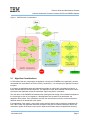
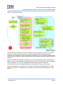
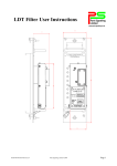
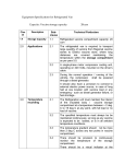
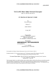
Coherent Accelerator Processor Interface
(CAPI) for POWER8 Systems
Decision Guide and Development Process
Bruce Wile
IBM Systems and Technology Group
20 October 2014
®
© Copyright International Business Machines Corporation 2014
Printed in the United States of America October 2014
IBM, the IBM logo, and ibm.com are trademarks or registered trademarks of International Business Machines Corp.,
registered in many jurisdictions worldwide. Other product and service names might be trademarks of IBM or other
companies. A current list of IBM trademarks is available on the Web at “Copyright and trademark information” at
www.ibm.com/legal/copytrade.shtml.
Other company, product, and service names may be trademarks or service marks of others.
All information contained in this document is subject to change without notice. The products described in this
document are NOT intended for use in applications such as implantation, life support, or other hazardous uses where
malfunction could result in death, bodily injury, or catastrophic property damage. The information contained in this
document does not affect or change IBM product specifications or warranties. Nothing in this document shall operate
as an express or implied license or indemnity under the intellectual property rights of IBM or third parties. All
information contained in this document was obtained in specific environments, and is presented as an illustration. The
results obtained in other operating environments may vary.
You may use this documentation solely for developing technology products compatible with Power Architecture®.
You may not modify or distribute this documentation. No license, express or implied, by estoppel or otherwise to any
intellectual property rights is granted by this document.
THE INFORMATION CONTAINED IN THIS DOCUMENT IS PROVIDED ON AN “AS IS” BASIS. In no event will IBM
be liable for damages arising directly or indirectly from any use of the information contained in this document.
IBM Systems and Technology Group
2070 Route 52, Bldg. 330
Hopewell Junction, NY 12533-6351
The IBM home page can be found at ibm.com®.
20 October 2014
Decision Guide and Development Process
Coherent Accelerator Processor Interface (CAPI) for POWER8 Systems
Contents
1
2
Decision Guide Overview ..................................................................................................................... 4
Is the CAPI Developer Kit Right for You? ............................................................................................ 4
2.1
Algorithm Considerations .............................................................................................................. 5
2.2
Skill Considerations ....................................................................................................................... 6
2.3
Physical Considerations ................................................................................................................ 7
3
CAPI Developer Kit Process ................................................................................................................ 7
List of Figures
Figure 1: CAPI Decision Considerations ....................................................................................................... 5
Figure 2: CAPI Solution Process .................................................................................................................. 8
20 October 2014
Page 3
Decision Guide and Development Process
Coherent Accelerator Processor Interface (CAPI) for POWER8 Systems
1 Decision Guide Overview
This document is for individuals or organizations who are considering creating a solution on the Coherent
Accelerator Processor Interface (CAPI) Developer Kit available for IBM® POWER8™ systems. Before
using this decision guide, read the CAPI for POWER8 Systems White Paper, which is available at
http://www.ibm.com/support/customercare/sas/f/capi/home.html.
The CAPI Developer Kit enables you to create a custom processing engine that is a peer to the POWER8
cores. Your solution will have two parts: an application running on the POWER8 core and the acceleration
unit running on a field-programmable gate array (FPGA). You need specific skills to create both parts of
the solution.
This document helps you decide whether to purchase a CAPI Developer Kit. If you do, you will receive the
CAPI User’s Manual, which describes interfaces, programming paradigms, programming libraries, FPGA
parameters, and all other implementation details.
This document has two main sections. The first assists you in deciding if your algorithm will work in a
CAPI solution. The second section describes the process you follow to create a CAPI solution and
enables you to construct a high-level implementation plan.
2 Is the CAPI Developer Kit Right for You?
Several considerations drive your decision about whether to create a CAPI solution using the CAPI
Developer Kit. Figure 1 on page 5 shows a flowchart of the decision-making process. This section follows
the flowchart and describes each decision.
Is this an existing algorithm or new?
If this is a proposal for a solution based on a new algorithm, follow the “Algorithm Considerations” section
of the flowchart. This section helps you decide if your algorithm is a good candidate for a CAPI solution.
Existing application or an FPGA/ASIC solution?
You are mapping an existing algorithm to a CAPI solution. If your existing algorithm is a software
application, also follow the “Algorithm Considerations” section of the flowchart. However, if you previously
implemented this algorithm in hardware, bypass the “Algorithm Consideration” section and proceed to the
“Skill Considerations” section.
20 October 2014
Page 4
Decision Guide and Development Process
Coherent Accelerator Processor Interface (CAPI) for POWER8 Systems
Figure 1: CAPI Decision Considerations
2.1
Algorithm Considerations
A CAPI solution has two components: an application running on a POWER8 core (“application”) and the
accelerated work executed on an FPGA or ASIC (“accelerator”). You must split your algorithm into these
two parts.
In all cases, the application opens and starts the accelerator by using basic commands from libcxl.h, a
library included with the CAPI Developer Kit. The application “owns” the accelerator until all work is done.
At that point, the application closes the accelerator, again using libcxl.h commands.
The work done on the POWER8 core between the opening and the closing of the accelerator depends on
the overall type of work in your algorithm. If the application sets up work for the accelerator, the
application is the master. If the accelerator receives work from an external source such as an Ethernetattached network, the accelerator is the master.
If the application is the master, it sets up the control structure and the data on which the accelerator will
work. When ready, the application starts the accelerator using the work element descriptor (WED) as a
command or pointer to the work or work queue. While the accelerator works, the application can query
20 October 2014
Page 5
Decision Guide and Development Process
Coherent Accelerator Processor Interface (CAPI) for POWER8 Systems
the accelerator about its status using memory-mapped I/O (MMIO) commands. For its part, the
accelerator can signal events to the application by using interrupts or by setting values in memory. When
the accelerator completes its work or work queue, the application can either give the accelerator more
work or close the connection.
If the accelerator is the master, it is still initialized by the application and receives a WED. In this case, the
WED can contain pointers to where the accelerator will write its completed work. After that, the
accelerator receives external control or data. The accelerator processes the incoming work and usually
signals the application upon completion of each packet of work.
In either master/slave paradigm, the application and the accelerator share the same virtual memory
space. This simplifies the programming algorithm and allows the application and accelerator to pass data
back-and-forth, do pointer chasing, and communicate in a straightforward, low-latency fashion.
With this background, the CAPI solution architect needs to decide how to split the algorithm between the
application and the accelerator. Use the information in this section to decide if your algorithm fits the CAPI
paradigm.
Algorithm has a computationally heavy component?
Deep computing and specialized algorithms are prime candidates for CAPI. Examples include long
mathematical routines with multiple parameters such as Monte Carlo algorithms. CAPI can also help any
kind of time-critical computing because the speed of the FPGA or ASIC reduces the overall execution
time. Other examples include pattern processing, data analytics, Ethernet packet processing, JPEG or
video manipulation, machine learning, facial recognition, healthcare image analysis, records processing,
and engineering modeling.
In these cases, you partition the processing component onto the accelerator and the application does the
setup. In most cases, the heavy computation can be separated from the data preparation, and you
can move to the “Skill Considerations” section of the flowchart.
Does your algorithm have parallelism?
Algorithms with parallel streams can also fit into the CAPI paradigm. In this case, the application offloads
one or more of the streams to the accelerator. You can design the accelerator to have multiple, separate
processing engines that all work in parallel. The separate streams can send data back and forth to each
other or to the application. As long as one or more of the streams can be offloaded, your algorithm will
work in the CAPI paradigm, and you can move to the “Skill Considerations” section of the flowchart.
2.2
Skill Considerations
To create a CAPI solution, you need to have programmers and logic designers available to do the work.
However, with OpenCL for CAPI, you can create CAPI solutions with programming skills only.
The number of programmers and logic designers required depends on the complexity and performance
requirements of your algorithm, as well as the schedule for creating the solution. Your architect will need
to make the skills sizing after assessing these factors and understanding Section 3, the CAPI Developer
Kit Process on page 7.
20 October 2014
Page 6
Decision Guide and Development Process
Coherent Accelerator Processor Interface (CAPI) for POWER8 Systems
2.3
Physical Considerations
There are two key questions to answer to decide if your algorithm will work on the CAPI Developer Kit
FPGA from a physical standpoint.
Will your algorithm fit on the Developer Kit FPGA?
The IBM-supplied power service layer (PSL) co-resides on the FPGA with your acceleration engine. The
PSL handles communications, address translation, and caching of data for the accelerator to work with
the POWER8 core. The PSL comes as a preplaced entity on the FPGA and runs at 250 MHz. The PSL
uses just under 25% of the Stratix V FPGA’s adaptive look-up tables (ALUTs), arrays, and digital signal
processors (DSPs). For the complete device specifications, see
http://www.altera.com/devices/fpga/stratix-fpgas/stratix-v/stxv-index.jsp .
For estimation purposes, plan on your algorithm fitting in 70% of the overall ALUTs, arrays, and DSPs.
Table 1 shows the maximum remaining resources available for the accelerator functional unit (AFU) after
placing the PSL.
Table 1: FPGA Resources Available for the AFU
Item
Total Available for AFU
ALUTs
M20K memory blocks
DSP
341,548
1874
188
Does the Developer Kit Card have the necessary I/Os?
If your algorithm requires I/O resources in addition to logic blocks on the FPGA, see the specifications for
the CAPI Developer Kit card (http://www.nallatech.com/PCI-Express-FPGA-Cards/pcie-385n-alterastratix-v-fpga-computing-card.html). Generally, the card has DRAM and SFP+ 10 Gb connectors.
If either of these answers indicates that the CAPI Developer Kit will not work, you might still have options
if you can use the SFP+ connectors on the card to split your algorithm to an external engine. In this case,
the FPGA on the CAPI Developer Kit card contains logic for interfacing to the application through the PSL
and can contain some of your accelerator engine. The rest of the accelerator engine resides off card on
your own custom board, using the SFP+ high-speed connection to communicate between them.
3 CAPI Developer Kit Process
Best practices for creating a CAPI solution dictate using the rigorous development process outlined in this
section. The CAPI User’s Manual has additional details. After deciding to move forward with creating a
CAPI solution, plan on two phases: a high-level design (HLD) phase and an implementation phase.
Figure 2 on page 8Figure 2: CAPI Solution Process shows the entire process in flowchart form.
20 October 2014
Page 7
Decision Guide and Development Process
Coherent Accelerator Processor Interface (CAPI) for POWER8 Systems
Figure 2: CAPI Solution Process
The HLD phase is a critical step in an effective design process. In this phase, you map out the specific
performance targets, decide on structures for communications between the application and the
accelerator, and understand the CAPI implementation methodology. Then you develop a detailed division
of work between the algorithm and the accelerator and model your design using the POWER8 Functional
Simulator.
When you successfully complete the HLD phase, you enter the implementation phase. Implementation
details come from the HLD decisions and the CAPI User’s Manual. In this phase, you write the application
and the accelerator. You can use the POWER8 Functional Simulator again to validate the
communications between your application and the accelerator before running on a real system.
Also during implementation, you build your FPGA image alongside of the preplaced PSL logic. Finally,
you test your solution on a POWER8 system and make any required fixes before deploying your CAPI
solution.
20 October 2014
Page 8