1
APPLICATION NOTE
DIME II Temperature and power management
www.nallatech.com
Sep 2003
NT302-0039 – Issue 2
1. Introduction
Being able to monitor and react to changing environmental requirements and conditions are key elements in good system
design. This application note details how this can be achieved using the temperature monitoring features provided through
Nallatech’s FUSE software and DIME II hardware. This is primarily achieved using software calls that provide an instantaneous
temperature and voltage. There is also an embedded temperature FPGA alert that allows the user FPGA design to complete
the feedback loop between software and the hardware.
This application note covers all user aspects of the DIME II temperature and voltage management features such as: Applicable
Nallatech hardware, technical specifications, software interfacing and design considerations.
1.1 Abbreviations
•
FUSE
-
Field Upgradeable Software Environment
•
DIME
-
DSP and Imaging Module for Enhanced FPGAs
•
API
-
Application programming interface
1.2 Applicable Nallatech hardware
All DIME II motherboards such as the BenONE and the BenNUEY support the temperature and power management
functionality with the exception of the BenERA. All DIME II modules support this functionality with the exception of the
BenBLUE and the BenFAD. For software compatibility please ensure that the latest FUSE software is installed.
2. Technical Specifications
2.1 Temperature
All temperatures provided in degrees Celsius and are accurate to +/- 1 degree.
Range: 0 to 256 degrees Celsius.
Approximate time for an API call: 15milli-seconds.
2.2 Voltage
All voltages are given in millivolts and are accurate to +/- 100 millivolts.
Range: 0-5 Volts.
Approximate time for an API call: 15milliseconds.
Note: The times given for the API calls where taken with the card connected over the PCI interface. These are approximate
times and depend upon several factors such as operating system, PCI chip set, PCI bus usage and processor speed. The times
given where taken using a DELL Dimension 4100 which had an Intel® Pentium 3 800MHz processor.
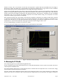
3. Example monitoring utility
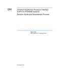
A precompiled utility called dispdata.exe is provided with this application note and can be found in the bin folder. The main
screen from this utility is shown in Figure 1.
This utility provides an easy way to monitor a card/modules voltage and temperature. Full details of how to use this utility are
provided in the monitoring utilities help system.
NT302-0005 - Issue 1 - 19 Sep, 2003
www.nallatech.com
Page 1
Figure 1 - Card Monitoring Utility
The source code for this utility can be found in the source code\card monitor folder.
4. Example accelerator control utility
A precompiled utility called acelctrl.exe is provided with this application note and can be found in the bin folder. The main
screen from this utility is shown in Figure 2.
This utility controls the temperature of a design to ensure that the design is always running within a desired temperature
range. The designs temperature is controlled by varying oscillators one’s (sys clock) frequency. The program periodically polls
(approximately once every half second) the interrupt pin to determine if the temperature alert signal has been activated and
therefore if the FPGAs temperature is exceeding the thresholds. Upon determining if the device is over or under temperature
the oscillators frequency is accordingly raised or lowered until the design is running within the desired temperature range. The
temperature alert signal is then cleared and the utility then resumes its normal polling mode. After the design has been within
the temperature thresholds for a period of time (specified by the Number of Loops parameter) the design is deemed to be at a
stable temperature and the program will terminate details the designs optimal clock frequency for the program constraints and
the designs power consumption. There are several parameters that control the utility. These are detailed below:
Maximum FPGA Temperature: This is the upper temperature threshold. A design that reaches this temperature is deemed to
be exceeding its temperature constraints and the clock frequency will be lowered. Set this to one degree more than the
maximum temperature that your design can be run at.
Minimum FPGA Temperature: This is the lower temperature threshold. Set this to one degree less than the minimum
temperature that your design can be run at.
Initial Clock Frequency: This is the starting clock frequency for the monitor.
Alert Wait Time: Once a threshold is exceeded and the clock frequency either raised or lowered the program will wait a
period of time for the temperature to come back within limits before either further reducing the clock frequency or clearing
the alert. This period of time is the alert wait time. If the FPGA rapidly heats or cools then this should be to set to a shorter
period of time than if the design is slower to react to temperature changes.
NT302-0005 - Issue 1 - 19 Sep, 2003
www.nallatech.com
Page 2
Number of Loops: This is the number of times that the temperature is polled within the thresholds before the design is
deemed to be stable. The polling rate is approximately every half-second. Setting this to a large number increase confidence
that the final frequency found is a stable frequency for this design with the given constraints.
Number of alert handler calls: Every time either of the temperature thresholds is exceeded an alert handler is called within the
program to bring the FPGAs temperature back within the thresholds. The number of alert handler calls is the maximum
number of times this alert handler is called before the utility will terminate. This parameter is included since if the valid FPGA
temperature range is too small then the designs temperature will oscillate between being over temperature and under
temperature and the program would run indefinitely.
Max clock limit warnings: This is the number of times that the oscillators are allowed to be running at either there maximum
or minimum frequency and the design running out of its desired temperature range before the program is terminated. So for
example if the alert time is set to 15 and the maximum lock limit warnings set to 3 then the design could run over or under
temperature for a total of 45seconds before the program terminates and the design is held in reset.
A reference FPGA design is provided. See section 7 for details.
The source code for this utility can be found in the source code\accelerator control folder.
Figure 2 – Accelerator Controller Utility
5. Example C Code
Two example programs are provided with this application note.
The first example program further demonstrates how to use the API calls detailed in section 6. This can be found in the source
code/temperatureVandIcalls folder.
The second example shows how to use the interrupt feature combined with the temperature alert to ensure that a design
operates within its desired temperature constraints.
Once the card has been configured the alert limits for the temperature sensor are set. Then interrupts are enabled. The
program then waits for an interrupt, which is generated by the design whenever the temperature alert signal is activated. It
NT302-0005 - Issue 1 - 19 Sep, 2003
www.nallatech.com
Page 3
then brings the designs temperature back into the valid range by varying oscillator ones frequency. Once this has been achieved
the program clears the temperature alert and it resumes waiting for an interrupt.
IMPORTANT NOTE: This program can run indefinitely since it waits for an interrupt which will only occur if the FPGA
temperature exceeds the thresholds set using the defines MAXALERTTEMP and MINALERTTEMP.
This example can be found in the source code/temperatureinterrupt folder.
6. C/C++ API functions
The voltages can either be returned for the whole module or simply for one of the individual power supplies depending upon
the API calls arguments.
Details of what each of these four power supplies are controlling can be found in your motherboard/modules user manual. As
a rough guide these are:
Power Supply
Description
Power Supply A
Memory supply
Power Supply B
DIME I/O supply. Powers the iob's of the FPGA that allows motherboard to
module communications
Power Supply C
FPGA Core Supply
Power Supply D
Multipurpose supply. e.g. supplies any secondary FPGA on the module
Table 1: Power Supply usage details
Note that for the BenNUEY the on board FPGAs core power supply is power supply A.
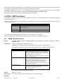
The C/C++ API functions detailed below have been taken out of the C/C++ API Developers Guide.
6.1 DIME_ModuleControl
Syntax
DWORD DIME_ModuleControl(DIME_HANDLE handle, DWORD ModuleNum, DWORD CmdMode,
DWORD Value)
Arguments
handle is a valid handle to a DIME carrier card.
ModuleNum is the module that is being addressed. Note modules are numbered from 0.
CmdMode: This argument is used to specify what particular aspect of module is to be controlled.
CmdMode
Description
dinfTEMPALERTMAX
This command mode is used to set the maximum temperature
level for the temperature alert signal. Once set if the FPGA die
temperature exceeds this temperature the then the temperature
alert signal is triggered. Note that the power on default setting
for this temperature is 255 degrees Celsius.
Value should be the integer value that the maximum alert should
be set to in degrees Celsius.
dinfTEMPALERTMIN
This command mode is used to set the minimum temperature
level for the temperature alert signal. Once set if the FPGA die
temperature falls below this temperature the then the
temperature alert signal is triggered. Note that the power on
default setting for this temperature is 0 degrees Celsius.
Value should be the integer value that the minimum alert should
be set to in degrees Celsius.
dinfTEMPALERTCLEAR
This clears the temperature alert signal if set. Note that if either
the maximum or minimum temperature limits are still exceeded
then the alert signal will immediately be set.
Value should to set to 0.
Table 2: DIME_ModuleControl CmdMode argument options
Value: This argument is command mode specific.
Return
Returns –1 on error.
Description
This function is used to control certain aspects of the selected module.
Example
NT302-0005 - Issue 1 - 19 Sep, 2003
www.nallatech.com
Page 4
{
DWORD MaxAlert=65;
DWORD MinAlert=0;
DWORD ModuleNumber=0;
//Set the max and min alert levels
if(DIME_ModuleControl(hCard1,ModuleNumber,
dinfTEMPALERTMAX,MaxAlert)==0){
printf("Maximum FPGA Temperature set to %d
degrees.\n",MaxAlert);
}
if(DIME_ModuleControl(hCard1,ModuleNumber,
dinfTEMPALERTMIN,MinAlert)==0){
printf("Minimum FPGA Temperature set to %d
degrees.\n",MinAlert);
}
//this code should be place in your temperature alert handler
//once you've dealt with the alert and desire to clear the alert
//line to the FPGA
if(DIME_ModuleControl(hCard1,ModuleNumber,
dinfTEMPALERTCLEAR,0)==0){
printf("The temperature alert line for module %d has been
cleared.\n",ModuleNumber);
}
}
Figure 3: Setting the maximum and minimum temperature alert limits and clearing an alert
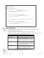
6.2 DIME_ModuleStatus
Syntax
DWORD DIME_ModuleStatus(DIME_HANDLE handle, DWORD ModuleNum, DWORD CmdMode)
Arguments
handle is a valid handle to a DIME carrier card.
ModuleNum is the module that is being addressed. Note modules are numbered from 0.
CmdMode: This argument is used to specify what particular aspect of module status information is to be
returned. The table below gives details of the available command modes.
CmdMode
Description
dinfFPGATEMP
This command mode returns the die temperature of the FPGA
in degrees Celsius. Temperatures are accurate to +/- 1 degree.
dinfMODULETEMP
This command mode returns the temperature of the module in
degrees Celsius. Temperatures are accurate to +/- 1 degree.
Note that this temperature is measured next to the User FPGA
and hence usually follows the FPGA temperature. It shows the
temperature of the module as a whole but not one specific
device.
dinfTEMPALERTMAX
This command mode is used to set the maximum temperature
level for the temperature alert signal. Once set if the FPGA die
temperature exceeds this temperature the then the temperature
alert signal is triggered. Note that the power on default setting
for this temperature is 255 degrees Celsius.
dinfTEMPALERTMIN
This command mode is used to set the minimum temperature
level for the temperature alert signal. Once set if the FPGA die
temperature falls below this temperature the then the
temperature alert signal is triggered. Note that the power on
default setting for this temperature is 0 degrees Celsius.
Table 3: DIME_ModuleStatus CmdMode argument options
Return
The return value is dependant upon the command mode. Returns –1 on error.
Description
This function returns module status information.
Example
NT302-0005 - Issue 1 - 19 Sep, 2003
www.nallatech.com
Page 5
//read the temperature alert levels and both the module and FPGA
//temperatures
{
DWORD ModuleNumber=0;
DWORD FPGATemp,ModuleTemp,MaxAlert,MinAlert;
//Read the FPGA temperature (degrees c)
FPGATemp=DIME_ModuleStatus(hCard1,ModuleNumber,dinfFPGATEMP);
//Read the module temperature (degrees c)
ModuleTemp=DIME_ModuleStatus(hCard1,ModuleNumber,dinfMODULETEMP);
//Read the maximum alert threshold temperature (degrees c)
MaxAlert=DIME_ModuleStatus(hCard1,ModuleNumber,dinfTEMPALERTMAX);
//Read the minimum alert threshold temperature (degrees c)
MinAlert=DIME_ModuleStatus(hCard1,ModuleNumber,dinfTEMPALERTMIN);
}
Figure 4: Reading the temperature alert levels and the FPGA and module temperatures
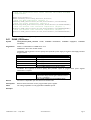
6.3 DIME_PPSStatus
Syntax
DIME_PPSStatus(DIME_HANDLE handle, DWORD ModuleNum, DWORD SupplyNum, DWORD
CmdMode)
Arguments
handle is a valid handle to a DIME carrier card.
ModuleNum: This is the module number.
SupplyNum: This argument is used to specify what particular power supply is targeted. Valid supply numbers
are given below.
SupplyNum
Description
dppsSUPPLYA
Power Supply A is selected.
dppsSUPPLYB
Power Supply B is selected.
dppsSUPPLYC
Power Supply C is selected.
dppsSUPPLYD
Power Supply D is selected.
dppsALLSUPPLYS
All supplies are selected.
Table 4: DIME_PPSStatus Supply Number options
CmdMode: This argument is used to specify what particular aspect of programmable power supplies
information is required.
CmdMode
dppsVOLTAGE
Description
This command mode selects that only voltage information is
returned. The voltage returned is given in millivolts and has an
error of +/- 100millivolts.
Table 5: DIME_PPSStatus Command Mode options
Return
The return is dependant upon the selected command mode.
Description
Returns status information for the programmable power supplies.
Note
The voltage capabilities are only applicable to DIME II systems.
Example
NT302-0005 - Issue 1 - 19 Sep, 2003
www.nallatech.com
Page 6
//Get the Voltage for module 0 power supply C.
{
DWORD Voltage;
Voltage=DIME_PPSStatus(hCard1,dppsMODULE0,
dppsSUPPLYC, dppsVOLTAGE);
printf("Core Voltage is %d millivolts.\n", Voltage);
//Get the Voltage for all of module 0.
Voltage=DIME_PPSStatus(hCard1,dppsMODULE0,
dppsALLSUPPLIES, dppsVOLTAGE);
printf("The total Voltage for Module 0 is %d.\n", Voltage);
}
Figure 5: Getting information on the power supply voltages
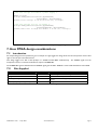
7. User FPGA design considerations
7.1 Introduction
An example design has been specified to give an example of a high toggle-rate design which uses the Temperature Sensor Alert
signal as an Interrupt to the PCI Interface.
This design toggles over 75% of the flip-flops in a 2V3000 Virtex2 FPGA simultaneously. The ALERT# signal from the
Temperature Sensor is inverted and clocked to output an INTERRUPT.
The INTERRUPT signal is ACTIVE when the ALERT# signal goes ACTIVE. ALERT# is active LOW and INT# is active HIGH.
7.2
Files Supplied
File Name
File Type
Description
MaxPower.vhd
VHDL File
Toplevel design file for reference design
invd.ngc
NGC File
Synthesised file. The toplevel VHDL file references this file.
BenADDA_2V3000_FF1152.ucf
User Constraint File
User Constraint File for design. Requires BenADDA 2v3000
FF1152.
maxpower_with_alert_interrupt_2v3000_ff1152.bit
Bit File
Configuration file for BenADDA 2v3000 FF1152.
Table 6: FGPA Reference Design Files
NT302-0005 - Issue 1 - 19 Sep, 2003
www.nallatech.com
Page 7
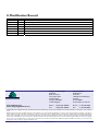
8. Modification Record
Date
14, Nov 02
19.Sep 03
Issue #
1
2
Comments
Document Introduction
Updates to Figure 1
www.nallatech.com
email: [email protected]
Europe & Asia-Pacific:
Nallatech
Boolean House
One Napier Park
Cumbernauld
Glasgow G68 0BH
United Kingdom
North America:
Nallatech Inc
Suite 300
12565 Research Parkway
Orlando
Florida 32826
United States of America
Phone: +44 (0)1236 789500
Fax:
+44 (0)1236 789599
Phone: +1 407 384 9255
Fax:
+1 407 384 8555
2003 Nallatech Ltd. All Rights Reserved. The Nallatech name and the Nallatech logo are trademarks of Nallatech Ltd. All other trademarks are the property of their respective
owners.
Nallatech Ltd. does not assume any liability arising out of the application or use of any product described herein; nor does it convey any license under its copyrights, or any rights of
others. Nallatech Ltd. reserves the right to make changes, at any time, in the order to improve reliability, function, or design and to supply the best product possible. Nallatech Ltd.
cannot assume responsibility for the use of any circuitry described other than circuitry entirely embodied in its products. No other circuit patent licenses are implied. Nallatech Ltd.
will not assume responsibility for any circuits shown nor represent that they are free from patent infringement or of any other third-party right. Nallatech Ltd. assumes no obligation
to correct any errors contained herein or to advise any user of this text of any correction if such be made. Nallatech Ltd. will not be liable for the accuracy or correctness of any
engineering or software support or assistance provided to a user.
NT302-0005 - Issue 1 - 19 Sep, 2003
www.nallatech.com
Page 8