1
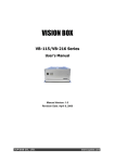
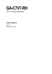
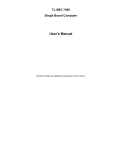
User's Manual
KM-150B with FEB-7000 main board, 15 inch LCD
Federal Communications Commission (FCC)
This equipment has been tested and found to comply with the limits for a Class A digital device,
pursuant to Part 15 of the FCC Rules. These limits are designed to provide reasonable
protection against harmful interference in a residential installation. This equipment generates,
uses, and can radiate radio frequency energy and, if not installed and used in accordance with
the instructions, may cause harmful interference to radio communications. However, there is no
guarantee that interference will not occur in a particular installation. If this equipment does
cause harmful interference to radio or television reception, which can be determined by turning
the equipment off and on, the user is encouraged to try to correct the interference by one or
more of the following measures:
Reorient or relocate the receiving antenna.
Increase the separation between the equipment and the receiver.
Connect the equipment to an outlet on a circuit different from that to which the receiver is
connected.
Consult the dealer or an experienced radio/TV technician for help.
Shielded interconnect cables and shielded AC power cables must be employed with this
equipment to insure compliance with the pertinent RF emission limits governing this device.
Changes or modifications not expressly approved by the system’s manufacturer could void the
user’s authority to operate the equipment.
Declaration of Conformity
This device complies with part 15 of the FCC Rules. Operation is subject to the following two
conditions:
1. This device may not cause harmful interference, and
2. This device must accept any interference received, including interference that may cause
undesired operation.
Important Safety Information
SAFETY INSTRUCTIONS
1.
2.
3.
4.
5.
6.
7.
Please read these safety instructions carefully.
Keep this User’s Manual for later reference.
Don’t use liquid or spray detergent for cleaning. Use only a moistened sheet or cloth.
For pluggable equipment, the socket-outlet should be installed near the equipment and
should be easily accessible.
Keep this equipment from extreme humidity areas.
Lay this equipment on a stable surface when installing.
Do not leave this equipment in a non-air conditioned environment, or in a storage
temperature above 60∘C. Such conditions may damage the equipment.
10. Place the power cord so that it will not be stepped on. Do not place anything over the
power cord. The power cord must be rated for the product and for the voltage and current
marked on the product’s electrical ratings label. The voltage and current rating of the cord
should be greater than the voltage and current rating marked on the product.
11. All cautions and warnings on the equipment should be noted.
12. If the equipment is not used for a long time, disconnect the equipment from the mains to
avoid damage.
14. Never open the equipment. For safety reasons, qualified service personnel should only
open the equipment.
15. If one of the following situations arises, get the equipment checked by service personnel:
a. The Power cord or plug is damaged.
b. Liquid has penetrated the equipment.
c. The equipment has been exposed to extreme moisture conditions.
d. The equipment does not work well or you cannot get it work according to the user’s
manual.
e. The Equipment has been dropped and damaged.
f. The equipment has obvious signs of damage.
Copyright
The information in this guide is subject to change without prior notice.
The manufacturer shall not be liable for technical or editorial errors or omissions contained
herein, nor for incidental or consequential damages resulting from the furnishing, performance,
or use of this material.
This manual contains information protected by copyright. No part of this manual may be
photocopied or reproduced in any form without prior written consent from the manufacturer.
© 2004 All rights reserved.
The software described in this guide is furnished under a license agreement or nondisclosure
agreement. The software may be used or copied only in accordance with the terms of the
agreement.
Product names mentioned herein may be trademarks and/or registered trademarks of their
respective companies.
First Edition July 2008
Table of Content
Chapter 1
Introduction
2
2
KM150B Characteristics ...................................................................................................... 2
How to Use This Manual...................................................................................................... 3
A Visual Tour of KM150B..................................................................................................... 4
What comes with KM150 .............................................................................................. 5
Fully Integrated Connector Panel.................................................................................. 6
Chapter 2
Hardware Setup
7
7
KM150 Assembly................................................................................................................. 7
Hard Disk Device Installation ........................................................................................ 7
Wireless installation ...................................................................................................... 9
Magnetic Card Reader Installation .............................................................................. 10
CMOS Setup ..................................................................................................................... 11
Wall Mount Assembly Instruction ....................................................................................... 12
Chapter 3
Software Setup
13
13
Operating System Installation ............................................................................................ 13
Windows 2K/XP installation ........................................................................................ 13
Chipset Driver Installation ................................................................................................. 14
Chipset Installation Utilities for Windows XP .............................................................. 14
VGA Driver Installation....................................................................................................... 17
VIA/S3G driver installation Windows 2000/XP ............................................................ 17
LAN Driver Installation ....................................................................................................... 18
Realtek RTL8139/810x LAN Driver Installation Windows XP ..................................... 18
Audio Driver Installation ..................................................................................................... 20
Audio Driver Installation for all Windows Operating Systems ...................................... 20
ELO Touch Tools Installation ............................................................................................. 23
ELO Touch Tools Installation for all Windows Operating Systems .............................. 23
ELO Control Panel...................................................................................................... 26
TouchKit Tools Installation................................................................................................. 29
TouchKit Tools Installation for all Windows Operating Systems .................................. 29
TouchKit Control Panel ............................................................................................... 32
Wireless LAN Driver Installation......................................................................................... 33
Wireless LAN Driver Installation for all Windows Operating Systems (Optional) ......... 33
Chapter 4
Specifications
34
34
MainBoard Configuration ................................................................................................... 35
KM-150 with FIR-C650 Main Board
Chapter 1
Introduction
KM150B Characteristics
•
KM150B uses a high speed processor capable of handling a high capacity of data
efficiently.
•
KM150B’s solid quality Aluminum housing distinguishes it from ordinary plastic
housings.
•
The KM150B touch terminal all-in-one is a robust, fanless design and is suitable for a
multitude of business types.
•
The LCD panel can be tilted at multiple angles for operator ease of use.
•
KM150B security is designed to prevent data theft. The Glaive system can be totally
diskless or may be equipped with an internal 2.5” HDD. Data Backup can be
constrained to Backup Servers in a network environment, or to (optional) removable
external Storage devices making it hard to copy data without authority.
•
KM150B is a fanless solution, which utilizes the solid aluminum housing to dissipate
any excess heat.
•
Additionally the aluminum casing also assures compliance to vigorous EMI radiation
testing.
2
KM-150 with FIR-C650 Main Board
How to Use This Manual
This manual contains all the information you need to set up and use KM150B. In addition, you
can also consult the manuals for the operating system and any additional hardware manuals for
peripherals that you may have added.
Chapter 1
Provides an introduction to KM150B and this manual.
Chapter 2
Provides all necessary information for all hardware setup.
Chapter 3
Provides the necessary information for installing the video drivers, touch screen
tools, audio, USB and LAN drivers.
Chapter 4
Lists all KM150 specifications and Information for the mainboard configuration.
Chapter 5
Provides information for troubleshooting the KM150B.
3
KM-150 with FIR-C650 Main Board
A Visual Tour of KM150B
Before you start, take a few moments to become familiar with KM150B.
4
KM-150 with FIR-C650 Main Board
What comes with KM150
The following items are standard with
KM150:
The following items are optional:
•
Magnetic Card Reader
(MCR) and bracket
Power adapter
•
Wireless LAN
•
User’s guide
•
2.5 inch Hard Disk
•
AC power cord
•
Main system with LCD panel
•
5
KM-150 with FIR-C650 Main Board
KM150 Dimensions
Fully Integrated Connector Panel
I/O Port
Power
Cash Drawer
Connector Type
Description
DC Power Connector
RJ11 Connector
Line Out
LAN
Earphone Connector
LAN RJ45 Connector
COM1
COM2
COM4
VGA
RJ45 serial ports
Connector
Connects AL-8510 to the power supply.
Cash Drawer Connector, 12 V Actuation support for
solenoid.
The audio port is for speakers.
The LAN port is used to hook Glaive to a local area
network.
This RJ45 serial ports COM1/COM2 / COM4 can
be used to connect serial devices
USB 1 & 2
USB Type A Connector
VGA Connector
The VGA port is for use with an external LCD or
CRT monitor.
This is a USB version 2.0 for additional devices
6
KM-150B with FEB-7000 Main Board
Chapter 2
Hardware Setup
KM150 Assembly
Please make sure that the power supply is disconnected when making any hardware changes to
KM150.
Hard Disk Device Installation
A standard KM150B comes without a hard disk drive (HDD), unless it is pre-requested.
Installing a HDD
1. Turn off power and remove power cable from main unit.
2. Remove 4 screws and
slightly separate the
LCD front frame from
the rear housing.
7
KM-150B with FEB-7000 Main Board
3. Lay the LCD face down
on a flat surface and
use the 4 screws
provided to mount the
HDD into the bracketed
space.
4. Install 2.5 inch hard
disk and connect SATA
cable.
5. Reassemble the LCD front frame and rear housing and secure with 4 screws.
6. Connect the main unit power.
Note: If the HDD does not work normally, please refer to troubleshooting
8
KM-150B with FEB-7000 Main Board
Wireless installation
An optional Wireless module can be installed the internal of the KM150.
Installing an Wireless
1. Turn off system power.
2. Remove 4 screws and slightly separate
the LCD front frame from the rear
housing.
3. Install Wireless module and cable
4. Install An
9
KM-150B with FEB-7000 Main Board
Magnetic Card Reader Installation
An optional Magnetic Card Reader (MCR) can be installed on the right side of the KM150.
Magnetic Card Reader (MCR)
Installing an MCR
5. Turn off system power.
6. Unplug the loopback from the MCR socket. The MCR socket is found on the right side on
the back of the main Unit.
7. Connect the MCR cable to the MCR
socket.
8. Secure two screws
Note: If the MCR does not work normally, please refer to troubleshooting.
Attention: The loopback or the MCR cable must be inserted in the socket for an external
keyboard to function with KM150B.
10
KM-150B with FEB-7000 Main Board
CMOS Setup
Please clear M/B FEB7000 JP5
Clear CMOS(JP5)
1-2
Protected
2-3
Clear
11
KM-150B with FEB-7000 Main Board
Wall Mount Assembly Instruction
Wall mount plate
Secure wall VESA mount
plate to the wall screws.
Connect DC In
Connector with cable from
power supple.
Hang the system unit onto
the wall mount plate.
Secure with two screws on
each side.
12
KM-150B with FEB-7000 Main Board
Chapter 3
Software Setup
Operating System Installation
KM150B units are widely used as networked Thin Client terminals and as such do not have an
internal hard disk drive. This is our factory default. However, users can upgrade KM150B later by
adding their own hard disk drive. Similarly the unit may have been ordered and delivered with a
hard disk drive installed. And unless the unit has also been pre-installed with an operating system,
then one will have to be installed.
Windows 2K/XP installation
Installing Windows 2K or XP can be performed on the Glaive quite simply
Items required:
A USB CDROM drive
1. Attach the USB CDROM drive to Glaive.
2. In the CMOS setup “Advanced Chipset setup” change the item “USB Device Legacy
Support” to “All Devices” this will allow booting from any USB bootable device.
3. Power on and modify CMOS BIOS settings to enable the USB CDROM to be the first
bootable device (see CMOS setup in the motherboard manual)
4. Insert the 2K or XP CDROM disk into the drive
5. Reboot the system
6. The Glaive will boot from CDROM drive and automatically start the setup programs
7. Follow the onscreen instructions for normal installation of 2K or XP
13
KM-150B with FEB-7000 Main Board
Chipset Driver Installation
Chipset Installation Utilities for Windows XP
1. Locate :\Chipset folder
2. Run Setup.exe
3. Click Next
4. Click “I Agree”
14
KM-150B with FEB-7000 Main Board
5. Click Next
6. Click Next
15
KM-150B with FEB-7000 Main Board
7. Click Next
8. Click Finish
16
KM-150B with FEB-7000 Main Board
VGA Driver Installation
VIA/S3G driver installation Windows 2000/XP
1. Open D:\VGA\VIA\ Twister\WIN2K&XP folder.
2. Run Setup.exe.
3. Select Next to continue.
4. Click Finish to complete the installation procedure and restart Glaive.
17
KM-150B with FEB-7000 Main Board
LAN Driver Installation
Realtek RTL8139/810x LAN Driver Installation Windows XP
1. Open Device Manger in the System Properties.
Select PCI Ethernet Controller
2. Click Next
3. Waiting Copy file.
18
KM-150B with FEB-7000 Main Board
4. Click Finish to complete the installation procedure and restart Glaive.
19
KM-150B with FEB-7000 Main Board
Audio Driver Installation
Audio Driver Installation for all Windows Operating Systems
1. Open D:\AUDIO
2. Run SETUP.EXE
3. Click Next
20
KM-150B with FEB-7000 Main Board
4. Click Next
5. Click Next
21
KM-150B with FEB-7000 Main Board
6. Waiting copy file
5. Click Finish to complete the installation procedure and restart Glaive.
22
KM-150B with FEB-7000 Main Board
ELO Touch Tools Installation
ELO Touch Tools Installation for all Windows Operating Systems
1. Locate D:\TOUCHSCREEN\ELO Touch
2. Select the relevant ELO folder for the operating system that you are using.
Example. If you are installing for a Windows 98 system, then select Elo Win9x_Me. If you are
installing under Windows 2000 or XP then select Elo Touch 2K_XP
3. Run Setup.exe
4. Click Next
5. Check “Install serial Touch screen Drivers.” And Click Next.
23
KM-150B with FEB-7000 Main Board
6. Read the “License Agreement” and click Yes if you accept it.
7. Select “Auto-detect Elo devices.” and click Next.
8. Select the COM port for the touch monitor. It is recommended that you select COM3 for
the touch screen, as this port is internally configured for touch operation.
9. Wait until the ELO Touch Tools have been installed.
24
KM-150B with FEB-7000 Main Board
10. Select View ELO touch screen control panel and click Finish.
IT MAY BE NECESSARY TO RESTART YOUR COMPUTER TO UTILIZE
YOUR TOUCHSCREEN FEATURES.
11. Click NEXT while this window appears after system finishs rebooting.
12. Click YES to restart your computer again.
After the system finishes rebooting follow the directions to calibrate ELO Touch Tools.
25
KM-150B with FEB-7000 Main Board
ELO Control Panel
This section explains the different options in the ELO control Panel.
General tab
The general tab allows you to:
•
Change the COM port your touch screen is set to.
•
Calibrate the touch screen with the Align button.
26
KM-150B with FEB-7000 Main Board
Mode tab
The Buttons tab allows you to:
•
Adjust all mouse emulation controls.
•
Change cursor properties
•
Enable or disable right mouse button utility.
Sound tab
The Sound tab allows you to:
•
To change sound properties for ELO touch tools.
27
KM-150B with FEB-7000 Main Board
Properties tab
The Diagnostics tab allows you to:
•
View Controller Information.
About tab
The About tab displays Information about ELO Touchsystems
28
KM-150B with FEB-7000 Main Board
TouchKit Tools Installation
TouchKit Tools Installation for all Windows Operating Systems
1. Locate D:\TOUCHSCREEN\eGalax Touch\Driver
2. Select the relevant eGalax folder for the operating system that you are using.
Example. If you are installing for a Windows 98 system, then select Win9x_Me. If you are
installing under Windows 2000 or XP then select Win2000_XP
3. Run Setup.exe
4. Click Next
5. Click Next
29
KM-150B with FEB-7000 Main Board
6. Click Next
7. Click Next
8. Click Next
30
KM-150B with FEB-7000 Main Board
9. Click Yes
10. Click Finish to restart your computer again.
After the system finishes rebooting follow the directions to calibrate the Touch screen.
31
KM-150B with FEB-7000 Main Board
TouchKit Control Panel
This section explains the different options in the TouchKit control Panel.
General tab
The general tab allows you to:
•
Change the COM port your touch screen is set to.
•
Calibrate the touch screen with the 4 pts Cal button.
32
KM-150B with FEB-7000 Main Board
Wireless LAN Driver Installation
Wireless LAN Driver Installation for all Windows Operating Systems
(Optional)
1. Open D:\Wireless LAN folder
2. Run Setup.EXE
3. Click Next
4. Click Next
33
KM-150B with FEB-7000 Main Board
Chapter 4
Specifications
Primary LCD Panel
KM-150B
VIA Eden (V4 Bus) series processors up to 1.0GHz with FSB
400
- VIA® CX700M
- ITE IT8712
- One 200-pin SO-DIMM socket (2nd as optional)
- Supports DDRII 400/533 SDRAM up to 1GB
- VIA CX700M integrated
- Shared system memory up to 128/MB
15” TFT LCD Panel (1024X768)
Primary Touch Panel
ELO 5-wire resistive touch panel or 4-wire resistive touch panel
Dual Display
Support independent dual display
Type II Compact Flash™ Disk. The Flash Disk provides 100%
compatibility with IDE hard disk.
- Support WDT function through software programming for
enable/disable and interval setting.
- Generate system reset or non-maskable interrupt (NMI)
Support Y2K Real Time Clock/Calendar with battery backup
for 7-year data retention
60 -Watt external power adapter.
CPU
Chipset
System Memory
Primary SVGA
Compact Flash Disk
socket
Watchdog Timer
Real Time Clock
/Calendar (RTC)
Power
®
Optional Features
Magnetic card
reader
HDD
Integrated Single/Dual/Triple Track MCR.
Internal 2.5” 40GB (or above) hard disk drive.
Power Consumption
20-30W Idle
(Standard system and accessing HDD)
34
KM-150B with FEB-7000 Main Board
MainBoard Configuration
35
KM-150B with FEB-7000 Main Board
36
KM-150B with FEB-7000 Main Board
This chapter describes how to connect peripherals, switches and indicators to
the FEB7000 board.
Label
JP1
JP3
JP5
JP7
JP8
JP9
JP10
Function
COM1/COM2/COM4 Ring/+5V/+12V
Selection
COM3/COM5 +5V/+12V Selection
Clear CMOS
LCD Voltage Selection
COM1 Mode Selection
COM2 Mode Selection
COM4 Mode Selection
Label
Function
BAT
CASH_DRAW
CF
COM1
COM2
COM3_COM5
COM4
DC_IN
DC_OUT
DIMM1
DIMM2
INVERTER
KB/MS
Battery Connector
Digital I/O connector
CompactFlash Slot
RS-232 Serial Port Connector
RS-232 Serial Port Connector
RS-232 Serial Port Connector
RS-232 Serial Port Connector
+12V DC In power connector
+12V DC Out power connector
DIMM Slot
DIMM Slot
INV Connector
PS2 Keyboard/Mouse Connector
10/100 or Base-Tx Ethernet
Connector
Audio 2 Channel Connector
LPT Port Connector
LVDS Connector
Mic in Connector
Mini PCI Slot
Internal Keyboard connector
Power LED
Power on Switch
SATA1 Connector
SATA Power connector
Audio Connector
USB0 Connector
USB1 Connector
USB2 Connector
VGA Display Connector
LAN
LINE_OUT
LPT
LVDS
MIC
MINI_PCI
MSR
PWR_LED
PWR_ON
SATA
SATA_PWR
SPEAKER
USB0
USB1
USB2
VGA
37
KM-150B with FEB-7000 Main Board
COM1/COM2/COM4 Ring/+5V/+12V Selection(JP1)
COM1
1-2
3-4
COM2
COM4
5-6
7-8 9-10 11-12 13-14 15-16 1718
+12V +5V Ring +12V +5V Ring +12V +5V Ring
Default
Default Default
COM3/COM5 +5V/+12V Selection(JP3)
1-2
+12V
3-4
+5V
Default
1-2
Protected
2-3
Clear
Clear CMOS(JP5)
LVDS Voltage Selection(JP7)
+5V
+3.3V
LVDS-LCD
5-6
1-2,3-4(Default)
COM1 Mode Selection (JP8)
JP8
1-2
3-5
4-6
Description
Short CTS-RTS
+12V or +5V output
Ground out
COM2 Mode Selection (JP9)
JP9
1-2
3-5
4-6
Description
Short CTS-RTS
+12V or +5V output
Ground out
38
KM-150B with FEB-7000 Main Board
COM4 Mode Selection (JP10)
JP10
1-2
3-5
4-6
Description
Short CTS-RTS
+12V or +5V output
Ground out
39