1
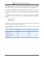
Flexcell® FX-5000™ Tension System 06-05-15 Rev 18 Culturing Cells in a Mechanically Active Environment™ Flexcell International Corporation 2730 Tucker Street, Suite 200 Burlington, NC 27215 800-728-3714 (919) 732-1591 FAX: (919) 732-5196 www.flexcellint.com COPYRIGHT © 2009 FLEXCELL INTERNATIONAL CORPORATION FLEXCELL® INTERNATIONAL CORPORATION TABLE OF CONTENTS One Year Limited Parts Warranty .......................................................................................... iii Dell Computer Warranty Information .................................................................................... iv Federal Communications Commission Radio Frequency Interference Statement .................. v FX-5000™ Quick Start Instructions ........................................................................................ vi 1. Flexcell® FX-5000™ Tension System Components ............................................... 1 2. Setup of the Flexcell® FX-5000™ Tension System ................................................ 1 2.1 Packing List ................................................................................................................. 1 2.2. Location of the FX-5000™ Tension System ............................................................... 1 2.3 Setup of the Computer and FX5K™ Tension FlexLink® ............................................. 2 2.4 Incubator Access Ports ................................................................................................. 3 2.5 Setup of the BioFlex® Baseplate(s) with Loading Stations™ and Culture Plates ........ 4 2.6 Connecting the System Vacuum Lines ........................................................................ 4 2.7 FlexSoft® FX-5000™ Software and System Power-up ................................................ 5 2.8 LCD Display on the FX5K™ Tension FlexLink® ........................................................ 5 2.9 Using Additional FX5K™ Tension FlexLinks® ........................................................... 5 3. Operation Instructions ................................................................................................... 7 3.1 Starting the FX-5000™ Program .................................................................................. 7 3.2. Using the FX-5000™ Tutorial ..................................................................................... 7 3.3 Main Display Window ................................................................................................. 7 3.4. Configuring Users ....................................................................................................... 9 3.5 Creating Regimens ....................................................................................................... 9 3.6 Creating a Regimen with a Custom Waveform Shape .............................................. 11 3.7 Assigning Regimens .................................................................................................. 12 3.8 Starting Regimens ...................................................................................................... 12 3.9 Simulating Regimens ................................................................................................. 13 3.10 Pausing Regimens .................................................................................................... 13 3.11 Resuming Regimens ................................................................................................ 13 3.12 Stopping Regimens .................................................................................................. 13 i FLEXCELL® INTERNATIONAL CORPORATION 3.13 Determine the Progress of the Regimen .................................................................. 13 3.14 Resetting the FlexLink® ........................................................................................... 14 3.15 Controlling the Vacuum Pump ................................................................................ 14 3.16 Data Analysis ........................................................................................................... 14 3.17 Shutting Down the System....................................................................................... 15 3.18 Exiting the FX-5000™ Program ............................................................................... 16 4. Addendums to the FX-5000™ Tension System..................................................... 17 For Optimal Performance of the Tension unit ................................................................. 17 5. System Troubleshooting ............................................................................................. 18 6. Application Notes ......................................................................................................... 21 Baseplate and Gasket Cleaning and Disinfecting ............................................................ 21 Running Low Frequency Regimens with BioFlex® Culture Plates ................................. 21 Waveform Shape Definitions ........................................................................................... 22 Flexcell® FX-5000™ Tension System Specifications............................................... 24 Appendix: FX-5000™ Tension System Dual Baseplate Operation ....................... 28 ii FLEXCELL® INTERNATIONAL CORPORATION ONE YEAR LIMITED PARTS WARRANTY Flexcell FX-5000 Tension System 1. 2. FLEXCELL INTERNATIONAL CORPORATION warrants to the original purchaser/customer all hardware components of the Flexcell FX-5000 Tension System serial #__ ______ _________for a period of one year from the date of delivery to the purchaser/customer to be free from manufacturing defects in workmanship or materials with the following exceptions, terms and conditions: a. ITEMS EXCLUDED FROM THE WARRANTY ARE: Dell OptiPlex desktop computer and monitor*, software, disks, manuals and external peripherals such as printers, mouse or track ball units, imaging devices, vacuum pumps, air tanks, electric voltage converters, compressors, surge suppressers and all other accessory equipment. b. DURING THE WARRANTY PERIOD, the purchaser/customer must notify Flexcell of any warranty claim in writing, by telephone, fax transmission or email identifying each defective part or specifically describe the exact problem no later than the last day the warranty is in effect. c. FLEXCELL AGREES to correct any defect in workmanship or material and supply new or rebuilt parts in exchange for defective parts upon completion and submission by purchaser/customer of a printed “Parts Return Authorization” form furnished by Flexcell. Parts must be properly packed in original container and shipped to our factory service center or distributor with all shipping costs prepaid if the unit is out of warranty coverage. If the original shipping box is not available, Flexcell will send the required protective shipping container. (Flexcell will recommend the insurance value for parts or equipment to be shipped.) Return carrier shipping costs will be paid by Flexcell from the service center. The purchaser/customer is solely responsible for payment of custom fees, taxes, holding fees or value added taxes. d. THIS LIMITED WARRANTY only covers failures due to defects in materials or workmanship which occur during normal use. It does not cover damage which occurs in shipment or failures of original equipment due to products identified as add-ons not manufactured by Flexcell International Corporation or its distributors nor does this limited warranty cover damages or failures which result from accident or disaster such as fire, explosion, flood, wind, lightning, or earthquake or misuse, abuse, neglect, mishandling, misapplication, alteration, faulty installation, modification or service by anyone other than our factory or distributor. Breaking the seal and opening the unit case or violating unit components will void the warranty. This warranty is extended only to the original purchaser/customer unless a transfer of ownership is approved by Flexcell in writing. e. LIMITED LIABILITY. Flexcell or its distributor’s only liability shall be to remedy any defect to comply with its warranty and return the repaired equipment to function as designed. Under no circumstances shall Flexcell or its distributors be liable for any special incidental or consequential damages based upon breach of warranty or contract or negligence. Such damages include, but are not limited to: loss of profits, revenue, loss of data, down time, customer’s material or time. f. DISCLAIMER OF WARRANTIES: The Limited Warranty expressed in the foregoing language is the only warranty applicable to this product. Any other warranty, expressed or implied warranty or of merchantability or fitness for a particular purpose are hereby disclaimed. No oral or written information or advice provided by Flexcell, through its agents or employees, in the use and functioning of the equipment shall in any way create a warranty or in anyway increase the scope of this limited warranty. g. DISCLAIMER: LANGUAGE. This warranty document, accompanying instruction manual and supplemental applicable laws appear in the English language. In the event of any inconsistency in the meaning of the words and terminology and any foreign language translation, the English language shall prevail. GOVERNING LAW. The performance of the duties and liabilities of the parties under the terms and conditions of this Limited Warranty shall be governed in all respects by the laws of the State of North Carolina, the United States of America. APPLICATION OF STATE LAWS: Some states do not allow the exclusion or limitation of consequential damages nor do some states allow limitations on how long an implied warranty lasts, so the above limitations may not apply to you. This warranty gives you specific legal rights and you may also have other rights that vary from state to state. 3. INTERNATIONAL CUSTOMERS. The full text of the foregoing limited warranty and all disclaimers is applicable to international customers/purchasers except when the purchase was made from an international distributor or reseller, the warranty will be covered through your distributor or reseller. If technical advisory support service is not available through your distributor or reseller, for service contact warranty headquarters by phone or fax. Within the United States only: 1-800-728-3714 (toll free) - Fax: 1-919-732-5196 International Customer’s telephone: 01-919-732-1591 - Fax: 01-919-732-5196 Email: [email protected] FLEXCELL INTERNATIONAL CORPORATION 2730 Tucker Street, Suite 200, Burlington, NC 27215 1-800-728-3714 (within the U.S. only) 1-919-732-1591 fax: 1-919-732-5196 http://www.flexcellint.com *Customers should contact Dell Inc. for all warranty questions or concerns with regards to the Dell OptiPlex computer and monitor. iii FLEXCELL® INTERNATIONAL CORPORATION Dell COMPUTER WARRANTY INFORMATION Dear Customer: Congratulations on your purchase of the Flexcell FX-5000 system. This system comes with a one (1) year warranty. The Dell computer that is included with this equipment will be transferred into the Principal Investigator and University’s name at the time of purchase. This computer comes with an excellent warranty through Dell. If you have any problems with this computer, you will contact Dell directly. The details of the warranty are listed below. You will need to have the service tag number and Express Service Code number, which are located on the side of the computer. Dell Hardware Limited Warranty Plus Onsite Service Extended Year Dell Hardware Limited Warranty Plus Onsite Service Initial Year Thank you choosing Dell ProSupport. For tech support, visit http://support.dell.com/ProSupport or call 1-866-516-3115 ProSupport for IT: Next Business Day Parts and Labor Onsite Response 2 Year Extended ProSupport for IT: Next Business Day Parts and Labor Onsite Response Initial Year ProSupport for IT: 7x24 Technical Support for certified IT Staff, 2 Year Extended ProSupport for IT: 7x24 Technical Support for certified IT Staff, Initial year iv FLEXCELL® INTERNATIONAL CORPORATION FEDERAL COMMUNICATIONS COMMISSION RADIO FREQUENCY INTERFERENCE STATEMENT This computing equipment has been type-tested and found to comply with the limits for a Class B digital device in accordance with the specifications for Subpart J of Part 15 of FCC Rules. These limits are designed to provide reasonable protection against harmful radio and TV interference in a residential installation. There is no guarantee that interference will not occur in a particular installation. The following instructions and precautions must be observed by the user when installing and operating this device: 1. The equipment must be operated in strict accordance with the manufacturer's instructions. 2. The unit(s) must be plugged into a properly-grounded power outlet and used with the power cord supplied with the unit(s), unmodified. 3. The unit must be operated with the factory-installed cover in place. 4. No modifications of the equipment can be made which may result in the equipment failing to meet the limits of the FCC Rules. 5. The equipment must be maintained in a satisfactory state of repair. 6. Shielded cables must be used with this equipment to ensure compliance with the FCC Rules. If the unit interferes with radio or television reception (which can be tested by turning the unit off and on) the user is encouraged to try the following procedure to correct the interference: 1. Reorient the antenna of the receiver. 2. Relocate the equipment to increase the distance between the unit and the radio/TV. 3. Connect the unit to an outlet on a different circuit from the receiver. 4. Consult with the dealer or an experienced radio/TV technician for advice on ways to reduce interference. v FLEXCELL® INTERNATIONAL CORPORATION FX-5000 QUICK START INSTRUCTIONS 1. Choose a location for the FX-5000™ Tension system that is near the incubator. 2. Place the computer, monitor, keyboard, mouse and FX5K™ Tension FlexLink® on a sturdy, flat surface. 3. Connect the keyboard, mouse and monitor to the computer according to the manufacturer’s instructions. 4. Connect the FlexLink® to the Ethernet port on the back of the computer using the Ethernet cable supplied (see Figs. 2 and 3, p.2). 5. Connect the computer, monitor and FlexLink® to a power source using a surge protector. 6. Connect the system vacuum to the SYSTEM port on the back of the FlexLink® and check the system vacuum supply (see manual section 2.6 for pump specifications recommendations). 7. Cut two lengths of tubing from those supplied: cut a 10' (3 m) length of the ¼” (6.4 mm) and cut a 10’ length of the ⅜” (9.5 mm) tubing. Connect each length of tubing to the rear connection of the FlexLink® in the FLEX IN and FLEX OUT ports, accordingly. Attach provided quick disconnects to the other end of each piece of tubing. 8. Place the Water Traps (see Fig. 1, p.2) inline with the FLEX IN and FLEX OUT tubing: a. Make cuts in the tubing for the Water Traps to be positioned as near as possible to the baseplate, outside of the incubator, so that the water will be trapped away from the FlexLink®. b. Place the Water Traps at a position below the FlexLink® unit. 9. Place the baseplate(s) in the incubator: a. Insert the ¼” (6.4 mm) and ⅜” (9.5 mm) tubing into the access opening of the incubator. b. Connect the quick disconnects for the ¼” (6.4 mm) and ⅜” (9.5 mm) tubing to the baseplate(s). c. Place four Loading Stations™ into the four baseplate wells (optional) and apply lubricant to the tops of the white buttons of the loading posts. d. Place four gaskets on four BioFlex plates and place a BioFlex® plate and gasket in each baseplate well. 10. Turn the FlexLink® and computer system ON. The Windows desktop should appear on the monitor. Double click on the FX-5000™ icon on the left-hand side of the screen to start the software. 11. In the Configure menu, select User Editor and register as a user. vi FLEXCELL® INTERNATIONAL CORPORATION 12. In the Regimen menu, select Create new and create a regimen by entering values into the appropriate spaces or click on the Run Wizard button in the bottom left-hand corner for a step-by-step procedure. When completed, click on Save Regimen. Exit the regimen editor. 13. In Controllers menu, select the appropriate FlexLink® number to which the regimen will be downloaded. 14. In the Regimen menu, select Assign. Choose the proper platform, user, and regimen (see section 3.7 for assignment instructions) from the drop-down menus. Confirm with a Yes to download the regimen. 15. Once the program is downloaded, click on Simulate in the main window display. Once satisfied that the regimen is correct, click on Stop. 16. Turn ON the vacuum system. Click on Start to run the regimen. The plates should begin flexing. Make a visual check to verify membrane movement. 17. To pause or stop the regimen, click on Pause or Stop at any time. Otherwise, the program will stop when the regimen is completed. 18. Check the Water Traps prior to each experiment to see if water is accumulating. Empty the Water Traps before they are more than half full. vii FLEXCELL® INTERNATIONAL CORPORATION 1. FLEXCELL® FX-5000 TENSION SYSTEM COMPONENTS 1. Dell OptiPlex desktop computer. Do not delete any software or change any settings on this computer. It has been preconfigured to operate the FlexSoft® FX5000™ software. Preinstalled software: FlexSoft® FX-5000™ Microsoft Windows 7 Microsoft Office 2010 Adobe Acrobat 2. 3. 4. 5. 6. 7. FX5K™ Tension FlexLink USB keyboard USB 2-button entry mouse 17” Flat panel monitor Accessory pack of nuts and ferrules Flexcell vacuum baseplate 8. Four gaskets 9. BioFlex 25 mm diameter Loading Stations™ 10. Silicone lubricant 11. Plexiglas cover 12. System Drying Filter device 13. 25 ft small blue tubing (¼” (6.4 mm) O.D.) for FLEX IN connection 14. 25 ft clear tubing (⅜” (9.5 mm) O.D.) for FLEX OUT connection 15. 25 ft large blue tubing (⅜” (9.5 mm) O.D.) for vacuum source connection 16. Flexcell FX-5000 Tension System user’s manual and other ancillary manuals for computer and monitor 17. Surge protected outlet strip 18. Water Trap (x2) 19. Vacuum source (optional) 2. SETUP OF THE FLEXCELL® FX-5000™ TENSION SYSTEM Do not power up the Flexcell® FX-5000™ Tension system until all connections among components have been properly made and checked! Never power up the computer or the FX5K™ Tension FlexLink® with the cover removed - an electrical shock hazard exists. Operation of the computer without the cover is in violation of FCC regulations and will void the warranty! 2.1 PACKING LIST Remove the packing list and check off the instrument components as they are removed from the shipping containers. If any parts are missing, contact Flexcell® International Corp. immediately. 2.2 LOCATION OF THE FX-5000™ TENSION SYSTEM Choose a location for the FX-5000™ Tension system (Fig. 1) that is adjacent and as close as possible to the CO2 incubator and vacuum source. A shorter distance in vacuum lines decreases the air flow resistance for elongation and release of the flexible bottomed culture plates, allowing for a greater range of flexing at higher frequencies. The length of the vacuum line should be a minimum of 4’ (1.2 m). All tubing and the Ethernet communications cable connect to the rear of the FX5K™ Tension FlexLink® (Fig. 2). All cables (mouse, monitor, keyboard, and Ethernet communications cables) will connect to the rear of the computer (Fig. 3). The length of the clear and blue tubing from the FlexLink® to the baseplate should be 10' (3 m) long to assure proper system performance. This Copyright 2009 Flexcell International 1 FLEXCELL, BioFlex, FlexLink and FlexSoft are trademarks of Flexcell International Corporation. MS Windows and MS Office are trademarks of the Microsoft Corporation. Adobe Acrobat is a trademark of Adobe Systems Inc. Dell OptiPlex is a trademark of Dell. General Notice: Other product names mentioned in this manual are for identification purposes only and may be trademarks of their respective owners. Flexcell International disclaims any and all rights in those marks. FLEXCELL® INTERNATIONAL CORPORATION length can vary if needed, but no more than 5' (1.5 m) longer or shorter. Cut the tubing after the system is fully set up to ensure of the proper length. The FX-5000™ Tension system will require a space 28.75” (73.03 cm) wide by 22.44” (57.00 cm) deep if the computer, FX5K™ Tension FlexLink® and monitor are placed side by side with the keyboard and mouse in front. The total weight of the system is 48.37 lbs (21.96 kg). Figure 3. Dell OptiPlex rear view 2.3 SETUP OF THE COMPUTER AND FX5K™ TENSION FLEXLINK® Setup the Dell OptiPlex desktop computer and peripherals according to the manufacturer’s instructions. Refer to Figures 1-5 for proper setup of the FX5000™ system instruments. Place the FX5K™ Tension FlexLink® next to the computer and connect the FlexLink® to the computer via the Ethernet cable provided. Figure 1. Flexcell® FX-5000™ Tension System If additional FlexLinks® have been purchased, they are to be placed side by side. For multiple FlexLinks® to be controlled by one computer, connect the Ethernet cable from each FlexLink® to an Ethernet Hub. Then, connect the hub to the Ethernet port on the back of the computer. Figure 2. FX5K™ Tension FlexLink® rear view Connect the system tubing as follows: 2 FLEXCELL® INTERNATIONAL CORPORATION representative should open the incubator access ports. 1. Connect the ⅜” (9.5 mm) O.D. blue tubing from the vacuum source to the SYSTEM port on the back of the FlexLink® (Fig. 1 & 2). 2. Attach the free end of the clear ⅜” (9.5 mm) tubing to the FLEX OUT port on the back of the FlexLink® (Fig. 2). 3. Attach the free end of the blue ¼” (6.4 mm) tubing to the FLEX IN port on the back of the FlexLink® (Fig. 2). The VENT port should be left open (Fig. 2). 4. Connect a Water Traps inline with the clear ⅜" tubing and the blue ¼” tubing. See the Addendum (pg 17, "B") for further details concerning the placement of the Water Traps. Once the access port has been located, insert the FLEX IN and FLEX OUT tubing through the access port into the incubator. Attach the ¼” (6.4 mm) blue tubing to the ¼” (6.4 mm) quick disconnect on the baseplate. Attach the ⅜” (9.5 mm) clear tubing to the ⅜” (9.5 mm) quick disconnect on the baseplate (Fig. 4). If two baseplates are to be used simultaneously, connect the baseplates using the configuration as shown in Figure 5. NOTE: Please see Appendix A (pg. 28) for the maximum allowable % elongations when using two baseplates simultaneously. NOTE: When connecting the tubing to the back of the FlexLink®, slip the brass nut with the nylon ferrule over the tubing, then push the tubing onto the fitting as far as possible and thread the nut onto the fitting. Tighten each nut by hand until the tubing is crimped to minimize vacuum leakage. Connect the power cables (115 VAC or 230 VAC) to the rear power inlet (FlexLink Power) of the FlexLink® (Fig. 2). If the available power supply is 115 VAC or 230 VAC, be sure the voltage selection switch ON the computer (Fig. 3) is set to 115 V or 230 V, respectively. When the instruments are completely set up, the power cords should be connected to a surge protected power strip and then to a 115 VAC or 230 VAC, 60 Hz power outlet. 2.4 Figure 4. Single baseplate connection INCUBATOR ACCESS PORTS Consult the operations manual of the CO2 incubator for the location of the incubator access ports. Most incubators have an access port at the top or the rear of the incubator. If this opening is not immediately apparent, consult the incubator manufacturer about the location of an access port. To prevent voiding the incubator warranty or encountering an electrical hazard, a trained incubator Figure 5. "T" connection for two baseplates 3 FLEXCELL® INTERNATIONAL CORPORATION 2.5 2.6 SETUP OF BIOFLEX BASEPLATE(S) WITH LOADING STATIONS™ AND CULTURE PLATES CONNECTING THE SYSTEM VACUUM LINES Connect the blue ⅜” (9.5 mm) vacuum inlet tubing to a vacuum source. A vacuum pump capable of producing a maximum vacuum of -100 kPa and a flow rate of, at least, 5.7 ft3/min (161 L/min) is necessary for optimal performance. Place the BioFlex® baseplate onto one of the incubator shelves. Be sure the shelf is level front to back and side to side in the incubator. 1. Attach the FLEX IN and FLEX OUT quick disconnect fittings to the respective fittings on the baseplate. Keep the tubing length between the vacuum source and FlexLink® as short as possible. Also, keep in mind that some vacuum systems will vary in flow rate and/or pressure level. To eliminate or reduce this effect, use of a pressure reservoir between the vacuum source and the FX5K™ Tension FlexLink® is recommended. 2. If using Loading Stations™, place the four sets of Loading Stations™ into the baseplate wells and apply silicone grease to the tops of the posts (see the Culture Plate and Loading Stations™ user’s manual for detailed instructions). Flexcell® International Corp. recommends the Leybold Trivac D8B Pump vacuum pump (includes the D8B pump system, power cable, gas ballast valve and AR 4-8 return filter) as a vacuum source as well as using a pressure reservoir. The vacuum pump and pressure reservoir can be purchased directly from Flexcell® International Corp. 3. Place the 4 red gaskets onto the bases of the four BioFlex® culture plates. Be sure that the gaskets are fully pressed onto the culture plates and that no parts are folded under. 4. Place the culture plates and gaskets into the baseplate wells. Check to be sure that the gaskets are not folded up at any point of contact with the baseplate. If the four gaskets feel loose within the plane of the baseplate (can be easily moved right or left, forward or backward without lifting the gasket out of the well), they should seal correctly. NOTE: Even with an optimal vacuum source, there will still be some system limitations due to airflow. Combinations of high frequencies and % elongations may not be achievable due to the high vacuum level in the short period of time requested. An example would be a regimen programmed to run a sine wave from 0–20% elongation at 1.0 Hz, using the 25 mm BioFlex® Loading Stations™. The system is not able to achieve the vacuum required to reach 20% in 0.5 seconds because of airflow limitations. The maximum % elongation may only reach 15%. The exact output is dependent on many system variables. See the Addendum on page 17 for suggestions on maximizing system performance. 5. Place the Plexiglas sheet with weights on top (5-10 lbs) over the culture plates to help seal the baseplate. NOTE: After a regimen is run for an hour or so, there should be little or no moisture visible in the lines or Water Traps. Condensation early on in the experiment indicates an air leak. If condensation is present, recheck the seals around each of the culture plates. To use the auto control pump feature, plug the vacuum pump power cable into the PUMP CONTROL CONNECTION outlet 4 FLEXCELL® INTERNATIONAL CORPORATION on the rear of the FX5K™ Tension FlexLink® (Fig. 2 and 6). directions can cause hardware malfunctions. NOTE: When using the auto pump control feature, the power cable from the FX5K™ Tension FlexLink® must be connected directly into the mains power. Failure to do so will cause damage to the FX5K™ Tension FlexLink®. The computer has Windows 7 installed on the hard drive. All backup software is provided with the system. Check all connections and connect the surge protector into an appropriate power outlet (115 VAC or 230 VAC). Turn ON the surge protector strip and check that the indicator light on the strip is lit. If the power light does not come on, the surge protector has failed. Replace the surge protector and attempt to determine what caused the surge protector to fail. Turn ON the power switches at the computer, monitor and FX5K™ Tension FlexLink®. The system should then boot and load Windows®. Select and double click on the FX-5000™ icon. See page 14 for additional comments on setting up the vacuum power to use the auto control feature. 2.8 FLEXSOFT® FX-5000 SOFTWARE AND SYSTEM POWER-UP ® and NOTE: Flexcell® recommends that the power saving or screen saver features in the Windows software are disabled. Allowing the hard drive to power down while an experiment is running may create the need to reboot the computer before data can be viewed, or before a regimen can be downloaded again. It is recommended that the monitor be put in “sleep” mode when not in use and that the computer be allowed to run at full power during an experiment. Figure 6. Flexcell® FX-5000™ Tension System power set-up with auto control pump feature 2.7 software LCD DISPLAY ON THE FX5K™ TENSION FLEXLINK® The front of the FX5K™ Tension FlexLink® box has an LCD graphic display. When the FX5K™ Tension FlexLink® is turned ON, the LCD will display the FlexLink® number (i.e., #1, #2, #3, or #4) and the regimen status (i.e., Idle, Ready, or Left (the time remaining, in minutes, of a running regimen). When a regimen has been downloaded and/or is running, the LCD will also display the user name, platform, and regimen name. See Table 1, below, for the display messages with various FlexLink® statuses. ™ The FlexSoft FX-5000 software ® (Flexcell Copyright Protected Software, Property of Flexcell® International Corporation, 2730 Tucker Street, Suite 200, Burlington, NC 27215) has been preinstalled on the hard drive. Keep the CD package included with your system and store it in a safe place. Be sure to shutdown Windows properly by using the Shut Down command activated by the Start button. Failure to follow the above 5 FLEXCELL® INTERNATIONAL CORPORATION regimens. Regimens with a combination of high frequencies and % elongation levels will require a more powerful vacuum source. The capability of the vacuum source with more than one FlexLink® will need to be tested experimentally with the users’ particular setup. FlexLinks® must be placed side-by-side during use. If the user desires to use the vacuum pump auto control feature with each FlexLink®, then separate vacuum pumps will need to be used with each FlexLink®. Table 1. Messages displayed on the FX5K™ Tension FlexLink LCD. FlexLink Status Power ON Regimen downloaded Regimen is running or being simulated Regimen has stopped 2.9 LCD message #1 Regimen: Idle Flexcell International Corp. www.flexcellint.com #1 Regimen: Ready User name Platform Regimen Name Flexcell International Corp. www.flexcellint.com #1 Regimen: Left 5 min User name Platform Regimen Name Flexcell International Corp. www.flexcellint.com #1 Regimen: Idle User name Platform Regimen Name Flexcell International Corp. www.flexcellint.com To connect additional FlexLink®(s) to the computer, connect the Ethernet cable from each FlexLink® to an Ethernet hub. Then, connect the hub to the Ethernet port on the back of the computer using the Ethernet communications cable provided. The LCD on the front of the FlexLink® will display the number (#1-4) that the FX5K™ Tension FlexLink® has been assigned at the time of production. NOTE: The numbering of each FX5K™ Tension FlexLink® will not depend on what order it appears in the connection chain, but according to the configuration of each FlexLink® as "FlexLink #1, FlexLink #2…etc" during production. USING ADDITIONAL FLEXLINKS® Using additional FX5K™ Tension FlexLinks® will allow two or more baseplates (platforms) with different regimens to run simultaneously. All tubing connections made to the first FlexLink® should be made exactly the same with any additional FlexLinks®. Each FlexLink® will have its own separate FLEX IN and FLEX OUT tubing for each baseplate. However, the SYSTEM tubing can be shared between FlexLinks® with "T" fittings as long as the vacuum source is capable of running two or more FlexLinks® with the programmed When powering up the FlexLink®(s) and computer, turn the FlexLink®(s) ON before the computer. To use a particular FlexLink®, select the appropriate FlexLink® number (#1, 2, 3, or 4) from the Controllers menu. Assign, download, and run regimens just as would be done when using one FlexLink®. 6 FLEXCELL® INTERNATIONAL CORPORATION 3. OPERATION INSTRUCTIONS 3.1 be downloaded. The FlexLink® number can be found on the LCD screen on the front of the FlexLink® controller box. STARTING THE FX-5000™ PROGRAM The Flexcell system should now be set up and ready for operation. Be sure that the system vacuum supply is adequate to operate the instrument(s) (see section 2.6). Turn ON the power switch on the computer, monitor and FX5K™ Tension FlexLink®. The system should then boot and load Windows®. Select and double click on the FX-5000™ icon (Fig. 7) on the desktop to start the FlexSoft® FX-5000™ software. A main display window will appear (see Fig. 9). Figure 8. FX-5000™ tutorial Figure 7. FX-5000™ icon 3.2 USING THE FX-5000™ TUTORIAL In the Help menu, click on View Tutorial to view the FX-5000™ tutorial at any time (Fig. 8). The tutorial will appear on the left side of the screen. The tutorial explains the main steps involved in configuring users, creating regimens, and starting regimens. The tutorial will start automatically, as a default setting, when the software is opened. To turn OFF this feature, uncheck the box marked “Show Tutorial at Startup”. 3.3 Figure 9. Main display window All of the remaining information and command button states in the main display window reflect the current state of the system for the currently selected FX5K™ Tension FlexLink®. MAIN DISPLAY WINDOW It is possible to simultaneously assign and run a different regimen for each of the attached FlexLinks®. The main display window (Fig. 9) for each FX5K™ Tension FlexLink® has several features that allow more precise monitoring of the regimen. To access this window, select the appropriate FlexLink® (FlexLink#n) from the Controllers menu, where “n” is the FlexLink® number to which the regimen will In the upper left hand corner of the window is a section labeled Plot Units. This function allows users to change the units of the yaxis: % elongation, kPa, strain, millistrain 7 FLEXCELL® INTERNATIONAL CORPORATION (mstrain), or microstrain (ustrain). To select a particular unit, click on the appropriate button beside the unit label. The next block to the right is a section used to display the current User, Regimen, Platform, and Run time. Run time has two blocks. The one on the left displays the elapsed regimen time, and the one on the right displays the remaining regimen time, using the following format: dd:hh:mm:ss (days:hours:minutes:seconds). The block at the top right contains the current regimen Step, Cycle, Jump (when a regimen step is using the Jump Back to option), minimum level (Min), and maximum level (Max). The minimum and maximum levels will be listed according to the units specified under the Plot Units section as the minimum and maximum points at which the membrane stretches with each cycle. The next block to the right is a section labeled Smoothing. One expects data patterns to represent normal distributions of a function describing a straight line, sinusoidal curve, etc. Therefore, the plotted points of a mathematical function should be a predictable data set that is “smooth” (i.e., a curve comprised of points whose coordinates are predicted by the function). For a straight line, the equation would be y = mx + b; for a power function, the equation may be y = x2 or some derivative thereof. In general, data patterns may be confounded with noise. For the case of the pressure plot as a function of voltage from the FX-5000™ Tension System pressure transducer, the rough data yield a plot with a coefficient of variation of only 0.01%. Therefore, the signal to noise ratio for the combined Flexcell® system of circuits, hardware and transducers is high, lending confidence in the displayed plot. Nevertheless, the user can select a data smoothing option that is a simple weighted average of the points. The Smoothing section contains the option of either applying no smoothing (None) to the data points returned from the FlexLink® or of applying a threepoint moving average filter (Moving Average) to the incoming data. Choose the desired affect by clicking on the appropriate button. The major portion of the main display window is taken up with a plot designed to show the current state of a simulated or running regimen. This plot is generated from the data returned by the FlexLink® during regimen activity. When using a platform configuration that uses vacuum to generate a downward stretching of the membrane (elongation), the vertical scale represents increasing elongation, vacuum or strain. When the selected unit of display is kPa, the vertical scale will start at 0.0 and move upwards as an increasing negative pressure level, indicating that a vacuum is being applied to the membrane to stretch it downwards. Below the box for Smoothing is a section used to show the current X and Y coordinates for the waveform. These are displayed when the left mouse button is clicked and held down in the graph area. When this is done, a pair of crosshairs appears and the coordinates at the intersection of the crosshairs are shown in the X and Y spaces. The crosshairs and values will track the mouse as long as the left mouse button is held down. The scale on the x- and y-axes can be changed by clicking on one of the two small double-arrow buttons at either end of the axis. The button with arrows pointing away from each other increases the axis scale, while the button with arrows pointing toward each other decreases the scale. 8 FLEXCELL® INTERNATIONAL CORPORATION Below the plot is a timeline that displays the percentage of the regimen that has been completed. To the right of the plot is a set of command buttons which allow the user to: 1) Start a regimen. 2) Stop a regimen. Figure 10. FX-5000™ user editor 3) Pause a regimen. To delete a user, click on the appropriate user name in the Existing Users box so that it is highlighted in blue and then click on Delete User. The program will ask for a confirmation and issue a warning, click Yes to confirm deletion. The user and any of the user's defined regimens will be deleted. 4) Resume a paused regimen. 5) Simulate a regimen. 6) Reset the controller. 7) Control the vacuum pump. To exit the Users window, click on Close. 8) Access Help. 3.5 9) Cancel the program. 3.4 CREATING REGIMENS NOTE: Please see Appendix A (pg. 28) for the maximum allowable % elongations when using two baseplates simultaneously. CONFIGURING USERS Prior to creating and downloading a regimen, a user needs to be registered. Once this task is completed, regimens can be personalized under the registered user name. Before beginning, a regimen must be created for downloading. In the Regimen menu, select Create new. A new window will appear entitled Regimens with a list of the existing users and their regimens (Fig. 11). In the Existing Users box, click on the user name under which the regimen is to be created. A list of current regimens created under this user will appear in the Regimens for Selected User box, unless no regimens have been saved under this user, in which case, this box will be empty. In the Configure menu, select User Editor. A new window will appear entitled Users (Fig. 10). To add a user, type in a user name (must be at least 4 characters) in the provided space and click on Add User. The new name should appear in the Existing Users box. To create a new regimen, click on Run Wizard in the bottom left hand corner. This option will bring up a step by step process of creating a new regimen. Alternatively, follow the sequence of steps below: 9 FLEXCELL® INTERNATIONAL CORPORATION 7) Enter the number of times for the regimen to repeat (0-65,535) in the box under Cycles. When moving out this box, the box underneath dd:hh:mm:ss will update to the calculated regimen time according to the set parameters. The format for this entry is days:hours:minutes:seconds. However, if the time is entered first, the program will calculate the number of cycles. 1) Type a regimen name in the box labeled Regimen Name. 8) To make a regimen step (except for the first step) return (jump back) to a previous regimen step, enter the return step number in the box under Back To. Then, type the number of times to repeat this process in the box under Repeat. Figure 11. FX-5000™ regimen editor 2) Choose the desired waveform shape under Shape by clicking on the downward arrow and selecting an entry from the drop-down list. For instance, if the user was entering Step 4 and wanted to return to Step 2 and repeat Steps 2 through 4 three times, enter 2 under Back To and 3 under Repeat when inputting Step 4. 3) Enter the desired minimum and maximum % elongation for the plate membranes (030%) in the boxes under Min and Max. 9) When the regimen step is complete, click on Add Step at the bottom. Every time a new/edited step is saved, the overall duration of the regimen will be calculated and displayed in the box labeled Duration next to the Step number box. If the total duration exceeds the maximum allowable duration, this value will be MAXIMUM, and the regimen cannot be saved. Adjust the time and/or cycle number to decrease the total duration time. 4) Enter the frequency for the waveform (0.01-5 Hz) in the box under Freq. 5) If a static regimen is required, enter the desired % elongation at which the membrane is to be held in the Max box. Enter 0 in the Min box, and 1.0 in the Freq box (Min and Freq are irrelevant for static regimens). 6) If a duty cycle for the waveform is to be defined, enter the desired value in the box under DC %. The duty cycle is the percent of time that the waveform shape remains on at the high (square wave) or rising (triangle) part of the waveform. Duty cycle only affects the triangle and square waves. 10) To add other steps to a regimen, click in the box labeled Step and type in the next step number. For example, the first step will automatically be Step 1. To add another step, delete the 1 and replace it with a 2. After this is completed, change the 10 FLEXCELL® INTERNATIONAL CORPORATION parameters as needed for the new step according to steps 2 to 9 above. 6 5 % Elongation 11) To delete a step that has already been added, click on the step in the window labeled Regimen Steps, which contains the list of steps. This will cause the step to be highlighted. Then click on Remove Step at the bottom of the window. Confirm the deletion by clicking on Yes when prompted. 3 2 1 0 0 100 200 300 400 500 600 700 800 900 1000 Time (msec) Example Custom waveform shape: Ramp waveform shape 12) After all steps and parameters have been entered, click on Save Regimen. Example Excel file: Ramp waveform shape 1 1. 2 2. 3 3. 4 4. 5 5. 0 5 5 5 5 5 13) To delete a regimen, simply double-click on the desired regimen name in the Regimens for Selected User box, and then click on Delete Regimen. Confirm the deletion by clicking on Yes. Example CSV file viewed in Notepad: Ramp waveform shape 1,1.5,2,2.5,3,3.5,4,4.5,5,5.5,0 NOTE: If the regimen to be deleted is currently assigned, the regimen must be removed from assignment before deleting. In the Regimen menu of the FX-5000™ software, select Create new. A new window will appear entitled Regimens with a list of the existing users and their regimens. In the Existing Users box, click on the user name under which the regimen is to be created. A list of current regimens created under this user will appear in the Regimens for Selected User box, unless no regimens have been saved under this user in which case, this box will be empty. 14) When finished with regimen editing, click on Close. 3.6 4 CREATING A REGIMEN WITH A CUSTOM WAVEFORM SHAPE In the top row of an Excel spreadsheet, enter the % elongation values for the desired waveform shape for one cycle. Enter one value per cell. Values should be chosen along a curve at even time intervals, i.e. every 100 msec (milliseconds). Save this spreadsheet as a .csv file (comma delimited file format) in the C:/FlexSyst directory. To create a new regimen, click on Run Wizard in the bottom left hand corner. This option will bring up a wizard to create a new regimen. Or, follow the sequence of steps below: 1) Choose Custom from the list of waveform shapes under Shape by clicking on the downward arrow and selecting this entry from the drop-down list. 11 FLEXCELL® INTERNATIONAL CORPORATION 2) Choose the appropriate file name under File by clicking on the downward arrow and selecting an entry from the drop-down list NOTE: Be sure to choose the platform that properly corresponds to the setup being used, otherwise the % elongation values will be incorrect. 3) Type a regimen name in the box labeled Regimen Name. For example: If using the 25 mm diameter Loading Stations™, click on BFlx Loading Station (25mm) for the choice of platform. 4) Enter the time interval in milliseconds between two % elongation values in the box under Time. If using the BioFlex® plates without the Loading Stations™, click on BFlx Plate, no Loading Stations for the choice of platform. 5) Enter the number of times for the regimen to repeat (0-65,535) in the box under Cycles. 6) When the regimen step is complete, click on Add Step at the bottom. Every time a new/edited step is saved, the overall duration of the regimen will be calculated and displayed in the box labeled Duration next to the Step number box. If the total duration exceeds the maximum allowable duration, this value will be MAXIMUM, and the regimen cannot be saved. Adjust the time and/or cycle number to decrease the total duration time. Figure 12. Assigning regimens for downloading to the FX5K™ Tension FlexLink®. If the download progresses, no further messages will appear, and the Start and Simulate buttons will be enabled. If an error occurred in downloading the regimen to the FlexLink®, a message will appear alerting the user of a problem, and the regimen will not be able to run. In which case, click Reset in the FlexLink® window, and then assign the desired regimen again. 7) Click on Save Regimen. 8) When finished with regimen editing, click on Close. 3.7 ASSIGNING REGIMENS In the Controllers menu select the appropriate FlexLink#n, where “n” is the FlexLink® number to which the regimen will be downloaded. In the Regimen menu, select Assign, then choose the Platform, User, and Regimen from each drop down menu (Fig. 12). A message box will appear to confirm regimen assignment. Click Yes. 12 FLEXCELL® INTERNATIONAL CORPORATION 3.8 STARTING REGIMENS To pause a simulated or running regimen, click on Pause in the main display window. Click on Yes when the program asks for confirmation. Pausing will cause the current simulation or actual running of the regimen to stop at the next cycle of the current regimen step. Pausing is different from stopping, in that pausing leaves the regimen at its current position, whereas stopping causes the regimen position to be set to the beginning of the first regimen step. To run an assigned regimen, click on Start in the main display window (Fig. 9) after the regimen has finished downloading. Be sure that the vacuum pump is ON and all other connections are made. The membranes should begin flexing and the assigned regimen will be in progress. The progress of the regimen for the currently selected FlexLink® will be monitored continuously. The displays for Run Time, Step #, Cycle #, Jump #, and Min and Max % will update, as will the actual waveform data returned by the FlexLink®. Additionally, a progress bar below the graph will display the percentage of the regimen that has been completed. 3.9 3.11 To resume a paused regimen, click on Resume in the main display window. This function is available only when a simulated or running regimen has been paused. The regimen will restart its prior activity (simulation or actual run) from its last point. SIMULATING REGIMENS 3.12 The Simulate button is used to simulate a regimen graphically without actually running it. Simulating a regimen will give the user an idea of the waveform output before actually running the regimen. To start a simulation, click on Simulate in the main display window. A waveform will begin moving across the graphic display. This waveform corresponds to the ideal waveform as generated by the FX-5000™ software, and is the actual waveform pattern sent to the FlexLink® during the download process. For certain waveforms (e.g. square waves), the idealized pattern may appear to have some unusual elements (e.g. rounded corners). The purpose of these unusual elements is to accommodate for the lag time during sudden changes in pressure (e.g. rising/falling edge of a square wave). Without these unusual elements, the valve controllers may oscillate for a period of time (e.g. dampened sine wave during beginning of plateau in a square waveform). 3.10 RESUMING REGIMENS STOPPING REGIMENS To stop a simulated or running regimen, click on Stop in the main display window. Click on Yes when the program asks for confirmation. Stopping causes the current activity to cease immediately, and sets the regimen position back to the beginning of the first regimen step. Stopping is different from pausing, in that pausing leaves the regimen at its current position so that it can be resumed from where it stopped. 3.13 DETERMINE THE PROGRESS OF THE REGIMEN The progress of the regimen for the currently selected FlexLink® will be monitored continuously. The displays for Run Time, Step number, Cycle number, Jump to number, and Min and Max % elongations will be updated in the upper right hand corner of the main display window. The actual waveform data returned by the PAUSING REGIMENS 13 FLEXCELL® INTERNATIONAL CORPORATION begins. Users will be prompted to select this option or not when creating a regimen. The status of the pump is indicated by a light box to the right side of the On/Off/Auto options. A green light indicates that the pump is ON, and a red light indicates that the pump is OFF. controller will also be continuously updated on the graph. A timeline progress bar below the plot illustrates the percent of the regimen that has been completed. 3.14 RESETTING THE FLEXLINK® Resetting a simulated or running regimen causes the current activity to stop at the next cycle of the current regimen step, and disassociate the regimen from the FlexLink® controller. To reset, click on Reset in the main display window. Click on Yes when the program asks for confirmation. The system will now be in state similar to that which exists when the FX5K™ Tension FlexLink® is first turned ON. 3.15 3.16 DATA ANALYSIS The FX-5000™ software has the capability of storing data (a set of waveform points) from a regimen run to a file on the hard drive. The filename consists of the FlexLink® number, a “V” or “C” code letter (V for vacuum, or C for compression), the regimen name and a sequence number. If a tension regimen is run three times on FlexLink#1, then there will be three data files on the hard drive with numbers ‘000’, ‘001’ and ‘002’, respectively (i.e., 1_V_regimenname_001.dat, 1_V_regimenname_002.dat, etc.). The file size depends on the regimen duration. The current settings take pressure data every 2 milliseconds (i.e., 500 points/sec or 1,800,000 points/hour). Therefore, a one hour regimen will have approximately a 4.0 Mb data file. To turn this feature OFF, please contact Flexcell®. CONTROLLING THE VACUUM PUMP On the right side of the FlexLink® window, the box labeled Pump allows the user to control power to the vacuum pump. NOTE: The vacuum pump must be plugged into the back of the FX5K™ Tension FlexLink® in the appropriate 110/220V plug prior to system powerup for this option to work, and the ON/OFF switch on the vacuum pump must be in the ON position. To see the stored data, in the Data Analysis menu, select Data Viewer. Open the appropriate .dat file from the C:/FlexSyst directory. Two new windows will appear (Fig. 13). In the window labeled filename:1, the data presented defaults to the raw data. In the window labeled filename:2, the data presented defaults to a moving average of the raw data with data averaged every 10 seconds. For manual control of the pump through the FlexLink®, use the On and Off options. If On is selected, the FlexLink® will turn the pump ON. If Off is selected, the FlexLink® will turn the pump OFF. For automatic control of power to the pump while regimens are running, select Auto prior to downloading the regimen. Once Auto is selected, the FlexLink® will turn the pump ON. The software will turn the pump OFF when a regimen is complete. This option also allows the pump to be turned OFF during a regimen step when a static waveform regimen is selected that has a 0% maximum elongation longer than 60 minutes. The pump will power up 10 minutes before the next regimen step 14 FLEXCELL® INTERNATIONAL CORPORATION seconds, range of 0.1-1000 seconds) shown in the Time (s) box. The Start time box can be set so that the data viewed in the plot begin at the specified time entered here. Use the timeline at the top of the graph to navigate through the regimen. Users can move the slider function within the timeline to manually progress through the regimen plot. If the user clicks on the arrows at either end of the timeline, the plot will progress to the next time period as set by the x-axis scale. For instance, if the scale is set to show 20 seconds of data and the user clicks on the right arrow button, the plot will progress to the next 20 seconds of data. Figure 13. FX-5000™ data display The y-Axis control box allows for automatic or manual control of the scale on the y-axis. If Auto is selected, the y-axis scale can be changed by clicking on one of the two small double-arrow buttons at either end of the axis. The button with arrows pointing away from each other increases the axis scale, while the button with arrows pointing toward each other decreases the scale. The minimum value is -2 kPa and the maximum is -100 kPa. If Manual is selected, the user can enter the upper and lower limits of the y-axis scale in the white boxes to the left side of the axis. The small double-arrows will not function if Manual is selected. 3.17 SHUTTING DOWN THE SYSTEM A system Drying Filter (Fig. 14) has been supplied with the FX-5000™. This device must be used whenever the system has been operated for more than one day and will not be operated again for more than one day. If the system will be operated again immediately after a one-day run or if the regimen runs for a longer period of time, the Drying Filter can be used at the conclusion of the usage period. The device and shutdown program will help to remove any moisture entrained into the valves during normal operation. This will greatly prolong the life of the valves and reduce expensive repairs. The x-axis scale allows for a time interval to be set between 0.1 and 1000 seconds. Click on one of the two small double-arrow buttons at either end of the axis to change this scale. The button with arrows pointing away from each other increases the axis scale, while the button with arrows pointing toward each other decreases the scale. To use the Drying Filter, first remove the orange plug in the bottom of the filter. Attach the fittings of the Drying Filter to the proper ports on the rear of the FlexLink® by replacing the lines running to the baseplate (FLEX IN and FLEX OUT). Assign the Drying regimen under the Shutdown user, using the BioFlex Plate, no Loading Stations platform. If the Drying regimen is not in the system or is erased, create a regimen with the The Input data box allows the user to switch the data in the graph from raw data to averaged data. If the Raw data option is selected, the graph will plot the pressure in – kPa over time, in seconds, for the selected regimen. If the Moving average option is selected, the graph will plot the average pressure over the designated time period (in 15 FLEXCELL® INTERNATIONAL CORPORATION following specifications: sine wave, 0-28%, 0.5 Hz, 1000 cycles; all other parameters are standard. The shutdown program will run for about 30 minutes. Dry room air will help to reduce moisture entrained into the lines and valves from the incubator atmosphere. Once the beads in the Drying Filter become pink, the filter is saturated and needs to be replaced. Figure 14. System Drying Filter 3.18 The baseplate should be removed from the incubator and stored flat to prevent warping. Do not hang the red gaskets on pegs to dry. They will stretch over time. EXITING THE FX-5000™ PROGRAM To exit the FX-5000™ software, in the Controllers menu, select Exit. 16 FLEXCELL® INTERNATIONAL CORPORATION 4. ADDENDUMS TO THE FX-5000™ TENSION SYSTEM FOR OPTIMAL PERFORMANCE OF THE TENSION UNIT: been operating continually for more than one day and will not be operated again for more than one day. See section 3.17 for instructions. A. Place the FlexLink® higher than the baseplate. If the FlexLink® can safely sit on top of the incubator, put it there. This will reduce the amount of moisture reaching the valves in the system. D. Place the enclosed Plexiglas© sheet over the culture plates and distribute a weight of about 5 -10 lbs (2.25 - 4.5 kg) evenly across the sheet as necessary to prevent vacuum leaks between the BioFlex® plate, gasket and baseplate. Lead donuts are recommended. As the gaskets are worn in this will no longer be necessary. B. It is necessary to place the included Water Traps inline between the FlexLink® and the baseplate. Be sure to place the Water Traps below the FX5K™ Tension FlexLink®. Humid air from the incubator tends to condense within the tubing lines. This moisture may in turn lead to problems with long term regimens. This fluid collection can be prevented from entering the FlexLink® by the insertion of the Water Traps. E. Make sure that the brass fittings on the back of the unit are tight and that the tubing is secure. F. Since the FX5K™ Tension FlexLink® is calibrated with 4 BioFlex® plates on the baseplate, Flexcell® recommends having 4 BioFlex® plates on the baseplate during strain, even if only one BioFlex® plate has been seeded with cells. The Water Traps need to be placed so that they are maintained in a vertical position. They should be checked frequently (twice a day initially while a regimen is running) and should be emptied when the Water Traps become half full. On the first trial, monitor the Water Traps every 15 minutes for the first two hours to be sure that a significant amount of water is not accumulating. If so, there may be a leak in the platform and/or gasket/BioFlex® plate assembly. See “System Troubleshooting, Problem 1” (pg. 18) to correct this problem. The valves and transducers may be damaged if moisture is allowed to accumulate. G. Achieving the highest possible combinations of % elongation and frequency: a) Shorten the FLEX IN, FLEX OUT, and SYSTEM tubing to their minimum possible lengths. See section 2.2 for minimum lengths. b) Use a more powerful vacuum source if recommended specs are not being reached with the current vacuum source (see section 2.6). C. Use the system Drying Filter and the shutdown program whenever the unit has 17 FLEXCELL® INTERNATIONAL CORPORATION 5. SYSTEM TROUBLESHOOTING NOTE: If the FX-5000™ system is not functioning properly and the solution is not clearly outlined or defined below, please contact Flexcell® before attempting any repairs. connected together, the leak is most likely in the baseplate or gaskets. Solution 1: Remove gaskets and plates from baseplate. Check to see that each gasket is firmly seated in each plate without any folds in the thin bottom lip of the gasket and with each inside corner butted up against each outside corner of the BioFlex® plate. Place each plate and gasket carefully into each baseplate well. Check to be sure that the gaskets are flatly seated in the wells; i.e., none of the sides touching the baseplate to the point that the gasket is not able to fully enter the well. Move each gasket forward and back and side to side within the well to be sure that they are somewhat loose in the plane of the baseplate. This will allow the vacuum pressure to pull the gaskets and plates firmly down to seal flat against the baseplate surface. Run a regimen. The plates and gaskets may require some initial hand pressure to start the seal. Place the Plexiglas cover and a couple of lead weights (approx. 10 lbs total; variable) on top of the plates. If there is still a noticeable leak, check all sides of each BioFlex® plate to see if the membrane is protruding from any side. If there is any noticeable membrane protrusion, remove this with a razor blade. Problem 1: Gaskets on baseplate are not sealing Symptoms: a. System is not performing to specified parameters (i.e., not reaching maximum % elongation value entered in regimen) b. Water Traps are filling with water quickly during use with incubator Test to determine if this is the problem: If experiencing symptom a, there is likely a leak or crimped tubing somewhere in the system. First, check all tubing to be sure that it is straight and not bent to restrict air flow. To find the location of any vacuum leaks, do the following: First, check all vacuum connections at the back of the FlexLink®. If these are tight and without noticeable leaks, then run a regimen with the baseplate and take note of the max and min % elongations. Disconnect the quick disconnects from the baseplate and connect them together. Take note again of the max and min %elongations. These values should change slightly because of the decrease in system volume, however, not by a significant amount (2% elongation or greater). The wave may also be somewhat choppy because of the low system volume. If the outputs were originally only slightly lower or higher than the inputs, the problem is likely not a leak but calibration. Call Flexcell® for further instructions. If the output max % elongation increases significantly when the quick disconnects are Problem 2: Regimen wave is flatlining Solution 2: Remove the SYSTEM vacuum line at the back of the FlexLink® and check to be sure that there is vacuum coming through the line. Check the VENT port at the back of the FlexLink® when the system is running to see if air is moving in or out. If not, it is possible that the valves are locked due to residue buildup. Try applying positive pressure to the VENT port to free the valves. 18 FLEXCELL® INTERNATIONAL CORPORATION Solution 5: When vacuum is pulled to expand the silicone membranes at the bottom of the BioFlex® wells, the volume of the well increases, pulling air into the well from the atmosphere. When the membranes contract, the air is pushed back out. Because of this cyclic airflow during any experiment, the fluid evaporation rate in the BioFlex® wells will increase. The best solution to this problem is to use more culture medium. If the regimen wave is flatlining but the plates are still cycling air pressure, try the following: Disconnect the blue 1/4" (6.4mm) FLEX IN tubing from the back of the unit and place a finger over the end of the tubing while a regimen is running. If air is cycling at the end of the tubing then the problem is with the FX5K™ Tension FlexLink®. Contact Flexcell® International for further instructions. Problem 6: “An invalid argument was encountered" error is shown when attempting to assign a regimen. Problem 3: Regimen wave is fluttering or not smooth Solution 3: This problem could be due to water in the valves or the system being out of calibration. Run the drying regimen with the Drying Filter (as described in the manual) to dry the system and valves. If this does not resolve the problem try running the drying regimen once more. If the problem continues, contact Flexcell® for further instructions. Solution 6: This problem is caused when a user name is entered into the software without any regimens listed under his/her name. If the assign function sees that a user has nothing to assign an error is displayed. Simply delete the user(s) without a regimen or make and save a regimen under the user(s) name(s). Problem 4: Programming a long regimen (1 day or more) but the software will not allow the regimen to be saved. Problem 7: Water is accumulating quickly in the Water Traps Solution 7: This problem is likely due to a poor gasket seal on the BioFlex® baseplate. See the solution to Problem 1 to correct this. Be sure to empty the Water Traps frequently if this problem occurs. Water accumulation in the FlexLink® can damage the valves. Solution 4: The software has a limit on the number of cycles that can be entered into any given step (65,535). If a regimen is programmed with a step that requires more than 65,535 cycles, the software will give an "invalid entry" error. To run the regimen for the time required additional steps will need to be programmed. This will not create any breaks in the regimen. Simply divide the total time in half (or as many times as is necessary) and make additional steps with the same parameters. See section 3.5 of the manual for instructions on programming additional steps. Problem 8: Cells are growing only in the center of the wells due to a) excessive volume of medium in the well, causing pooling of the cells in the middle of the well due to gravity or b) incomplete trypsinization or over-trypsinization of cells, causing clumping and uneven distribution of cells Problem 5: Plate wells are drying up during the experiment 19 FLEXCELL® INTERNATIONAL CORPORATION Solution 8: a) Use 2-3 ml of media at plating. After cell adhesion, add medium to 5 ml. Start a flexing regimen prior to cell attachment; cells will be distributed evenly over the growth surface during active flexing. b) Trypsinize once for about 10-15 minutes, or less, depending on the cell type being used. Problem 10: One or more of the FX5K™ Tension FlexLinks® connected to the system are not being recognized by the software. This is usually represented by the error message “Cannot Connect to Controller” when attempting to connect a FlexLink® to assign a regimen. Solution 10: This problem is usually due to a lack of communication between the computer and one or more FX5K™ Tension FlexLinks®. Check the FX5K™ Tension FlexLink® Ethernet port connection on the computer and the communications connection on the back of the FlexLink® to be sure that these are secure. Check the FlexLink® to see if the power is ON (the FlexLink screen should power on). If both of these conditions are true, close and restart the software. Try downloading the regimen again. If the problem is not resolved, call Flexcell® for further instructions. Problem 9: Cells are not attaching properly to the growth surface or are detaching during stretching Solution 9: This problem can be caused by plating too many cells. Try plating with a lower cell density—if the cells are not confluent, they will form a matrix with the collagen (or other matrix coating), attaching more securely to the growth surface. Also, check with Flexcell® to be sure that the best matrix coating for attachment of the particular cell type is being used. 20 FLEXCELL® INTERNATIONAL CORPORATION 6. APPLICATION NOTES BASEPLATE AND GASKET baseplate and gasket or whenever media is spilled onto these surfaces. Be sure that the openings and the channels in the baseplate are dry and clear of any obstructions before using. CLEANING AND DISINFECTING The black urethane baseplate should not be autoclaved or washed in a dishwasher because the high temperature will cause warping. The red rubber gasket should also not be autoclaved or washed in a dishwasher. Both baseplate and gasket should be cleaned with regular laboratory detergent, rinsed with warm tap water, followed by distilled or deionized water and allowed to dry. The baseplate should be dried and stored on a flat surface. Do not hang the red gasket on pegs to dry as the gasket can be stretched. Protect both pieces from UV light exposure. Do not store baseplate or gasket in incubator as the warm, humid conditions will promote growth of microorganisms. After cleaning and disinfecting, seal baseplate and gasket in a plastic bag. Store baseplate flat and be sure that the entire bottom of baseplate is supported to prevent warping. Store gasket away from UV light exposure. RUNNING LOW FREQUENCY REGIMENS WITH BIOFLEX® CULTURE PLATES To disinfect, use a mild bleach (commercial bleach solution such as "Clorox" or other laundry bleach solution is normally 5.25% sodium hypochlorite) solution (1:500, bleach to water) or a 1% benzalkonium chloride solution, which can be sprayed, poured or wiped on both pieces and allowed to stand on surfaces for at least 5 min. Rinse with distilled or deionized water. The above solutions are effective against yeast and fungi. A 70% ethanol solution also can be applied and pieces allowed to air dry, do not wipe dry. Tubing on the baseplate may be flushed with 70% ethanol, but be sure tubing is completely dry before connecting to the FX5K™ Tension FlexLink®. Contact time (time surface remains wet) of the above solutions is critical to the effectiveness of disinfecting. Times given are minimal and longer contact times are recommended in cases where contamination is severe. If running a low frequency or constant stretch regimen with the BioFlex® culture plate without Loading Stations™, keep in mind that the 2-2.5 mL of medium in the well may not cover the entire surface area of the BioFlex® well under stretch. When the membranes are stretched and held for long periods of time, the cells around the outer edge of the well will be exposed to open air and will be in danger of drying out. It is therefore necessary to use additional medium (3-5 mL) when running low frequency and high strain regimens on the BioFlex® plate without the Loading Stations™. Running Low Frequency Regimens With BioFlex Culture Plates, Flexcell International Corporation, July, 1997, 1p. The above decontamination procedure should be performed before and after each use of the 21 FLEXCELL® INTERNATIONAL CORPORATION WAVEFORM SHAPE DEFINITIONS ½ Sine Wave Sine Wave This waveform provides a smooth, physiological variation in pressure at the max% with a quick transition at the min%. This waveform provides a smooth, physiological variation in pressure from min% to max%. Triangle Wave Square Wave This waveform provides a linear-ramped rise to the max% and a linear-ramped fall back to the min%. This waveform provides the fastest possible rise to max%, followed by the fastest possible fall to min%. 22 FLEXCELL® INTERNATIONAL CORPORATION Heart (E) Wave Heart (P) Wave This waveform applies a pressure pattern that mimics the shape as seen on an electrocardiogram This waveform applies a pressure pattern that mimics the actual pressure wave generated by a heart beat. Static Wave This waveform applies a constant state of pressure. 23 FLEXCELL® INTERNATIONAL CORPORATION Flexcell® FX-5000™ Tension System Specifications 24 FLEXCELL® INTERNATIONAL CORPORATION FX-5000™ TENSION SYSTEM FEATURES Uses vacuum to deform a flexible-bottom culture plate yielding up to 33% substrate elongation Minimum strain resolution capability is 0.1% elongation Applies a defined, controlled, static, or cyclic deformation to growing cells in vitro Housed valving mechanism automatically regulates and maintains pressure to provide the specified strain regimen Capable of driving up to 4 independent FlexLink remote strain and/or compression controllers Capable of delivering frequency ranges from 0.015 Hz Works with BioFlex, Tissue Train and UniFlex culture plates Ability to program multiple frequency, amplitude and wave changes in one regimen Waveforms available: Static wave, Sinusoidal wave, Heart wave (Electronic and Pressure), Triangular wave, Square wave and custom waveforms Provides equibiaxial strain or unconstrained distension to the BioFlex culture plate membrane Optional: Tissue Train and UniFlex plates can be used in conjunction with Arctangle® Loading Stations™ to achieve uniaxial strain Optional: StageFlexer and StageFlexer Jr. devices allow strain application to cells while viewing in real time under an upright microscope Optional: FlexStop™ provides a way to prevent pressure-induced flexing of any number of BioFlex wells FX-5000™ TENSION COMPONENTS AND SPECIFICATIONS Dell OptiPlex Desktop Computer USB Keyboard USB Mouse 17" Flat panel Monitor FlexSoft® FX-5000™ V1.0 (Flexcell FX-5000 Software) and Microsoft Windows 7 FX5K™ Tension FlexLink controller Accessory Pack - nuts, ferrules Flexcell vacuum pressure baseplate, gaskets, and acrylic window for BioFlex culture plates BioFlex 25mm diameter Loading Stations and Lubricant Water Traps System Drying Filter 25 ft small blue tubing (¼” (6.4 mm) O.D.) for FLEX IN connection 25 ft clear tubing (⅜” (9.5 mm) O.D.) for FLEX OUT connection 25 ft large blue tubing (⅜” (9.5 mm) O.D.) for vacuum source connection Flexcell FX-5000 Tension System User's manual, Culture Plate & Loading Stations™ manual, Vacuum Source Connection Manual, Water Traps and Drying Filter Tech Report and other ancillary manuals for computer and monitor Surge protected power outlet strip TISSUE TRAIN® ACCESSORY KIT (OPTIONAL) (Note: If purchased as a system, the Tissue Train® Accessory Kit is substituted for the Flexcell® vacuum pressure baseplate, gaskets, and acrylic window for BioFlex® culture plates and BioFlex® Loading Stations™) Flexcell® vacuum pressure baseplate, gaskets, and acrylic window for Tissue Train® culture plates Arctangle® Loading Stations™ and Lubricant Trough Loader™ Loading Stations FX-5000™ TENSION COMPUTER SPECIFICATIONS Dell OptiPlex Small Form Factor Intel Core i5 processor (3.2 GHz) 250 GB SATA 6.0 Gb/s hard drive DVD +/- RW Drive 25 FLEXCELL® INTERNATIONAL CORPORATION 2 GB of DDR3 RAM Integrated video, Intel® HD2500 Operating System: Windows 7 Professional FX5K™ TENSION FLEXLINK COMPONENT SPECIFICATIONS Custom design vacuum controller board o Microprocessor sampling rate for display data transducer: 200 Hz o Microprocessor sampling rate for feedback/error (valve adjustment) transducer: 1 KHz 2 proportional-solenoid valves Ethernet port (RJ45) FX5K™ TENSION FLEXLINK® CALIBRATION SPECIFICATIONS Unconstrained Static Performance (low side transducers): Maximum allowable waveform variance from static line: ± 0.25% elongation Maximum % elongation error (actual vs. programmed): +/-0.6% elongation Maximum allowable transducer inaccuracy: +/-1.0 kPa Unconstrained Dynamic Performance (low side transducers): Maximum % elongation error (actual vs. programmed): +/- 0.5% elongation, at the following frequencies: <5% elongation, 0.5 and 1.0 Hz; 10 % elongation, 0.5 and 0.75Hz; >10% elongation, 0.5 Hz Maximum allowable transducer inaccuracy: +/-1.0 kPa BioFlex 25mm Loading Station Static Performance (high side transducers): Maximum allowable waveform variance from static line: +/- 0.25% elongation Maximum % elongation error (actual vs. programmed): +/-0.5% elongation Maximum allowable transducer inaccuracy: +/-2.0 kPa BioFlex 25mm Loading Station Dynamic Performance (high side transducers): Maximum % elongation error (actual vs. programmed): +/-0.75% elongation, at the following frequencies: <15% elongation, 0.5 and 1.0 Hz; >17.5% elongation, 0.5Hz Maximum allowable transducer inaccuracy: +/-2.0 kPa LOADING STATIONS™ SPECIFICATIONS 25mm Diameter Loading Stations™ (equibiaxial strain): Minimum achievable % elongation with the FX-5000™: 0.8% Maximum achievable % elongation with the FX-5000™: 21.8% 28mm Diameter Loading Stations™ (equibiaxial strain): Minimum achievable % elongation with the FX-5000™: 1.0% Maximum achievable % elongation with the FX-5000™: 15.9% 31mm Diameter Loading Stations™ (equibiaxial strain): Minimum achievable % elongation with the FX-5000™: 0.8% Maximum achievable % elongation with the FX-5000™: 6.0% Tissue Train® with Arctangle® Loading Stations™ (uniaxial strain): Minimum achievable % elongation with the FX-5000™: 1.6% Maximum achievable % elongation with the FX-5000™: 20.8% 26 FLEXCELL® INTERNATIONAL CORPORATION UniFlex® with Arctangle® Loading Stations™ (uniaxial strain): Minimum achievable % elongation with the FX-5000™: 1.1% Maximum achievable % elongation with the FX-5000™: 12.2% HT 24 Well Plate with Cylindrical Loading Stations™ (equibiaxial strain): Minimum achievable % elongation with the FX-5000™: 1.2% Maximum achievable % elongation with the FX-5000™: 8.0% FX-5000™ TENSION PHYSICAL SPECIFICATIONS FX-5000™ Computer: Size, W x H x D: Power Requirements: Weight (unit only): 3.65” x 12.45” x 13.40” (9.3 x 31.6 x 34.0 cm) 115/230V –8.8/4.3A or 4.3/2.2A – 60/50 Hz 15.0 lbs (6.8 kg) FX5K™ Tension FlexLink®: Size, W x H x D: Power Requirements: Weight (unit only): 10.5” x 7.0” x 18.5” (26.7 x 17.8 x 46.9 cm) 115/230V – 6/3A – 60/50 Hz 22.15 lbs (10.06 kg) Monitor 17”LCD Flat Panel: Size, W x H x D: Power Requirements: Weight (unit only): 14.6” x 15.7” x 7.1” (37.1 x 39.7 x 18.0 cm) 115V - 60 Hz Auto switch to 230 V 11.22 lbs (5.1kg) Bioflex® Baseplate Kit: (Item#BFBK-4000) Size, W x H x D: Power Requirements: Weight (boxed in kit): 15” x 12” x 6” (38.1 x 30.5 x 15.3 cm) N/A 9.5 lbs (4.3 kg) Tubing & Adaptor Kit: (TAK-4000) Size, W x H x D: Power Requirements: Weight (boxed in kit): 12” x 9” x 9” (30.5 x 22.9 x 22.9 cm) N/A 6.2 lbs (2.8 kg) FX-5000™ TENSION VACUUM REQUIREMENTS To achieve the maximum system capability, the minimum vacuum source requirements are: Maximum Vacuum: : -100 kPa Free Airflow Rate: 5.7 cfm (161 L/min) 27 FLEXCELL® INTERNATIONAL CORPORATION Appendix A FX-5000™ TENSION SYSTEM DUAL BASEPLATE OPERATION 28 FLEXCELL® INTERNATIONAL CORPORATION When using the FX-5000™ Tension System in dual baseplate operation, the user may notice a drop in the overall programmed % elongation, depending upon the desired % elongation and frequency of the regimen. This drop is due to the vacuum source being shared between both baseplates. It is, therefore, recommended that users reduce the frequency of such a regimen to 0.5 Hz or lower. A lower frequency will allow the FX-5000™ Tension System the correct amount of time to intake and exhaust the vacuum, which, in turn, gives the system enough time to reach the desired % elongation. For example, if an FX-5000™ Tension System is connected in the dual baseplate configuration using the BioFlex 25 mm Loading Stations and a regimen is programmed with the following variables: Waveform = Sine % Elongation = 20% Frequency = 1 Hz The maximum % elongation achieved might only be 10%. Reducing the frequency of the regimen to 0.5 Hz will produce an achievable % elongation of 18%. The maximum allowable % elongation for dual baseplate operation with the FX-5000™ Tension System is as follows: Platform BioFlex: 25 mm BioFlex: 28 mm BioFlex: 31 mm Tissue Train: Arctangle UniFlex: Arctangle HT BioFlex Frequency 1.0 Hz 10.0 % 6.5 % 2.0 % 10.0 % 5.0 % 6.0 % 0.5 Hz 18.0 % 11.0 % 3.5 % 16.0 % 8.5 % 8.0 % 29 FLEXCELL® INTERNATIONAL CORPORATION NOTICE The information in this document is subject to change without notice. Flexcell® International assumes no responsibility for any errors that may appear in this guide. This manual is believed to be complete and accurate at the time of publication. In no event shall Flexcell® International Corporation be liable for incidental or consequential damages in connection with or arising from the use of the manual. Opening the case of the FX5K™ Tension FlexLink® voids the warranty. Customers must contact Flexcell® International Corporation or an authorized distributor before opening the case on the FX5K™ Tension FlexLink®. 30