1
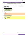
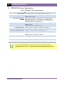
RFD-200 S3
PORTABLE RELAY TEST SET
USER’S MANUAL
Vanguard Instruments Company, Inc.
1520 S. Hellman Ave.
Ontario, California 91761, USA
TEL: (909) 923-9390
FAX: (909) 923-9391
July 2012
Revision 1
RFD-200 S3 USER’S MANUAL
REV 1
SAFETY SUMMARY
FOLLOW EXACT OPERATING PROCEDURES
Any deviation from the procedures described in this User’s Manual may create one or more
safety hazards, may damage the RFD-200 S3, or cause errors in the test results. Vanguard
Instruments Company, Inc. assumes no liability for unsafe or improper use of the RFD-200 S3.
All safety precautions provided in this manual must be observed during all phases of testing
including test preparation, test lead connection, actual testing, and test lead disconnection.
SAFETY WARNINGS AND CAUTIONS
Only trained operators shall use this device. All devices under test shall be off-line and fully
isolated.
DO NOT MODIFY TEST EQUIPMENT
To avoid the risk of introducing additional or unknown hazards, do not install substitute parts or
perform any unauthorized modification to any RFD-200 S3 test unit. To ensure that all designed
safety features are maintained, it is highly recommended that repairs be performed only by
Vanguard Instruments Company factory personnel or by an authorized repair service provider.
Unauthorized modifications can cause safety hazards and will void the manufacturer’s
warranty.
i
REV 1
RFD-200 S3 USER’S MANUAL
TABLE OF CONTENTS
CONVENTIONS USED IN THIS DOCUMENT ..................................................................................... 1
1.0 INTRODUCTION .................................................................................................................... 2
1.1 General Description and Features ................................................................................... 2
1.2 RFD-200 S3 Technical Specifications................................................................................ 4
1.3 Controls and Indicators .................................................................................................... 6
2.0 FUNCTIONAL DESCRIPTION ................................................................................................. 7
2.1 RFD-200 S3 Auxiliary Power Supply ................................................................................. 7
2.2 RFD-200 S3 Current and Voltage Sources ........................................................................ 7
2.3 Control Switches .............................................................................................................. 8
2.3.1. Voltage and Current Source Output Controls .......................................................... 8
2.3.2. LCD Contrast Control ................................................................................................ 8
2.4 Timer Start and Timer Stop Inputs................................................................................... 9
2.5 RFD-200 S3 Power Resistors ............................................................................................ 9
2.6 RFD-200 S3 External Voltage Input ................................................................................ 10
2.7 RFD-200 S3 External Current Input ................................................................................ 10
3.0 OPERATING PROCEDURES ................................................................................................. 11
3.1 Setting the Voltage or Current Source........................................................................... 11
3.2 Setting the RFD-200 S3 for a Time Delay Test ............................................................... 12
3.3 Using the RFD-200 S3’s Timer to Test Circuit Breaker Response Time ......................... 15
3.4 Using the RFD-200 S3’s Timer in Single Input Mode ..................................................... 17
3.5 Using the RFD-200 S3 to Plot a Current Transformer Excitation Curve ........................ 19
3.6 Using the RFD-200 S3 to Measure CT Primary and Secondary Currents ....................... 21
LIST OF TABLES
Table 1. RFD-200 S3 Technical Specifications ................................................................................. 4
Table 2. RFD-200 S3 Output Specifications .................................................................................... 5
Table 3. RFD-200 S3 Timing Accuracy ............................................................................................. 5
LIST OF FIGURES
Figure 1. RFD-200 S3 Controls and Indicators ................................................................................ 6
Figure 2. Typical Over Current Relay Connection ......................................................................... 14
Figure 3. Typical Circuit Breaker Timing Connection .................................................................... 16
Figure 4. Typical CT Excitation Test Connection ........................................................................... 20
Figure 5. Typical CT Turns Ratio Test Connection......................................................................... 23
ii
RFD-200 S3 USER’S MANUAL
REV 1
CONVENTIONS USED IN THIS DOCUMENT
This document uses the following conventions:
•
A key, switch, input, or knob on the RFD-200 S3 is indicated as [KEY], [SWITCH],
[INPUT], [KNOB].
•
RFD-200 S3 LCD screen output is shown as:
0mS 0.0CY
V Mtr: -0.003 V
Int I: 0.080 A
Ext I: -0.001A
•
Warning messages are indicated as:
Warning message
WARNING
•
Important notes are indicated as:
Note details
NOTE
1
REV 1
RFD-200 S3 USER’S MANUAL
1.0
INTRODUCTION
1.1
General Description and Features
The RFD-200 S3 is a portable relay test set that delivers performance verification testing of
electromechanical, electronic, and microprocessor-based protective relays in their operating
installations. The RFD-200 S3 is a rugged test set suitable for testing a variety of protection
relays operated in both indoor and outdoor environments. The unit’s ergonomic design and
intuitive control panel layout make it ideal for first-time users who have little or no training.
Built-in Digital Timer
The RFD-200 S3’s digital timer features independent start and stop trigger inputs designed to
measure the time between event transitions and to display the elapsed time in both milliseconds and cycles. The RFD-200 S3’s timer has three different trigger inputs – Internal Trigger,
Dry-Contact, or Wet-Contact. The Internal Trigger can start or stop the timer by sensing the
application or removal of the unit’s voltage or current source. The Dry-Contact can trigger the
timer by detecting a change in state of the dry-contact input. Similarly, the Wet-Contact can
trigger the timer by detecting a change in state of the voltage input. Thus, the three inputs can
trigger the timer by the presence or removal of the unit’s voltage or current source or by
changes in voltage or current states.
AC Current Source
An AC current source with three outputs (10A, 40A, and 100A) provides test current to relays.
The current source output can be programmed to synchronize with the RFD-200 S3’s timer.
After a test is completed, the test current reading is latched and displayed on the LCD screen.
This feature reduces the possibility of overheating the relay coils.
Auxiliary Output Contact
A set of NO/NC dry contacts (240 Vac/3A) change state when a test is initiated.
AC Voltage Source
An AC voltage source (0-250 Vac) is available. The AC voltage source output can be
programmed to synchronize with the RFD 200 S3’s timer.
DC Voltage Source
A 0 – 300 Vdc voltage source is also available. The DC voltage source can also be programmed
to synchronize with the RFD-200 S3’s timer
Volt Meter
One volt meter input (0 to 600 V input range) is available on the RFD-200 S3.
2
RFD-200 S3 USER’S MANUAL
REV 1
Ampere Meters
The test current is displayed on the unit’s backlit LCD screen that is viewable in both bright
sunlight and low-light levels. The current measuring range is from 0.00 to 250 A. A second
ampere meter is also available and can be used to read an external current input. The external
current input is rated at 6 A max and is protected by a circuit-breaker.
Auxiliary AC/DC Power Supplies
The RFD-200 S3 provides three power supplies (24 Vdc, 48 Vdc and 124 Vdc) for powering solidstate or microprocessor-based relays.
Built-in Power Resistor
The RFD-200 S3 features built-in power resistors for fine current adjustment.
3
REV 1
1.2
RFD-200 S3 USER’S MANUAL
RFD-200 S3 Technical Specifications
Table 1. RFD-200 S3 Technical Specifications
TYPE
Portable relay test set
INPUT POWER 100 – 120 Vac or 200 – 240 Vac (factory pre-set), 50/60 Hz
PHYSICAL SPECIFICATIONS Dimensions: 16.8”W x 12.6”H x 12”D (42.7 cm x 32.0 cm x 30.5 cm);
Weight: 35 lbs (15.9 kg)
AMPERE METER INPUT Internal input range: 0 – 250 A; Accuracy: 2% of reading ±10 mA
RANGES External AC input range: 0 – 6A; Accuracy: 1% of reading ±10mA
External DC input range: 0 – 6A; Accuracy: 0.5% of reading ±1 count
Measurement Method: True RMS for AC
VOLT METER INPUT RANGE 0 – 600.0V; AC accuracy: 1% of reading ±1 count; DC accuracy 0.5% of
reading ±1 count
Measurement Method: True RMS for AC
POWER RESISTORS
5 Ω/50 W, 1 Ω/50 W, 25 Ω/50 W, 100 Ω/50 W, 500 Ω/50 W
DRY CONTACT OUTPUT 3A, 240 Vac or 120 Vdc
AUXILIARY POWER SUPPLIES 24 Vdc @ 1 A, 48 Vdc @ 0.25 A, 124 Vdc @ 0.125 A
SAFETY
Designed to meet IEC61010 (1995), UL61010A-1, CSA-C22.2 standards
ENVIRONMENT Operating: -10°C to +50°C (+15°F to +122°F);
Storage: -30°C to +70°C (-22°F to +158°F)
HUMIDITY
90% RH @ 40°C (104°F) non-condensing
ALTITUDE 2,000 m (6,562 ft) to full safety specifications
OPTIONS Transportation case
WARRANTY
One year on parts and labor
The above specifications are valid at nominal operating voltage and at a
temperature of 25°C (77°F). Specifications may change without prior notice.
NOTE
4
RFD-200 S3 USER’S MANUAL
REV 1
Table 2. RFD-200 S3 Output Specifications
AC CURRENT OUTPUT
Range
No-Load Voltage
Load Voltage
Load Current
Load/Unload Times
10A
90 Vac
75 Vac
10 A
2 min / 15 min
40 A
25 Vac
20 Vac
40 A
1 min / 15 min
100 A
10 Vac
7.25 Vac
100 A
1 min / 15 min
100 A
10 Vac
3 Vac
250 A
1 sec / 5 min
Range
No-Load Voltage
Load Voltage
Load Current
Load/Unload Times
250 Vac
260 Vac
240 Vac
3A
10 min / 45 min
AC VOLTAGE OUTPUT
DC VOLTAGE OUTPUT
Range
No-Load Voltage
Load Voltage
Load Current
Load/Unload Times
300 Vdc
300 Vdc
250 Vdc
2A
10 min / 45 min
Table 3. RFD-200 S3 Timing Accuracy
RFD-200 S3 TIMER SECOND DISPLAY
IN SECONDS AND CYCLES (50/60 HZ PROGRAMMABLE)
Resolution
Accuracy
0 to 9.999 sec
Range
1 ms
± (1 ms + 0.01%)
10.00 to 99.99 sec
10 ms
± (10 ms + 0.01%)
100.00 to 999.999 sec
100 ms
± (100 ms + 0.01%)
TIMER CYCLES DISPLAY
Range
0 to 9.999 cycles
1,000 to 49,999 cycles / 50 Hz
Resolution
Accuracy
0.1 cycle
± (0.1 cycle + 0.01%)
1 cycle
± (1 cycle + 0.01%)
5
REV 1
1.3
RFD-200 S3 USER’S MANUAL
Controls and Indicators
The RFD-200 S3’s controls and indicators are shown in Figure 1. The purpose of the controls and
indicators may seem obvious, but users should become familiar with them before using the
RFD-200 S3. Accidental misuse of the controls will usually cause no serious harm. Users should
also be familiar with the safety summary found on the front page of this User’s Manual.
Figure 1. RFD-200 S3 Controls and Indicators
6
RFD-200 S3 USER’S MANUAL
2.0
FUNCTIONAL DESCRIPTION
2.1
RFD-200 S3 Auxiliary Power Supply
REV 1
The RFD-200 S3 provides 3 auxiliary power supplies (24 Vdc, 48 Vdc, and 125 Vdc) for powering
electronic relays. Each power supply is fuse-protected. The power supply outputs are controlled
by the auxiliary power supply [ON/OFF] button. The LED next to the [ON/OFF] button is
illuminated when the power supply output is turned on.
Only one auxiliary power supply can be selected at a time. The [PWS SELECT] button (item
21 in Figure 1) is used to select the power supply. The active power supply is indicated by an
illuminated LED above the corresponding voltage label.
2.2
RFD-200 S3 Current and Voltage Sources
The RFD-200 S3 front panel offers three AC current source terminals (100A, 40A, 10A). Only one
current source should be used at a time. The [METER SELECT] button is used to select
whether to display the current generated by the RFD-200 S3 or the current input at the [EXT
INPUT CURRENT] terminals. The [RFD-200 CURRENT] LED will be illuminated when an
internal RFD-200 current source is in use and the output current is displayed on the LCD. The
internal current is labeled as “Int I:” on the LCD screen as shown below:
0mS 0.0CY
V Mtr: -0.003 V
Int I: 0.080 A
Ext I: -0.001A
Internal Current
Two isolated voltage sources are also available, one 0-250 Vac and one 0-300 Vdc. Both the
current and voltage sources are controlled by the [OUTPUT CONTROL] knob .
7
REV 1
2.3
RFD-200 S3 USER’S MANUAL
Control Switches
2.3.1. Voltage and Current Source Output Controls
The RFD-200 S3’s voltage and current source outputs are controlled by the [UP ARROW] and
[DOWN ARROW] buttons. There are four control settings for the voltage/current sources:
•
START-ON
When this mode is selected, the RFD-200 S3 turns on the voltage/current sources and
starts the timer.
•
OFF
When this mode is selected, the voltage/current sources are turned off and the timer is
stopped.
•
ON
In this mode, both the voltage and current sources are simply turned on and remain on
until turned off by the user. The timer is not used in this mode. This mode is used to set
the voltage or current before performing a test.
•
START-OFF
In this mode, the RFD-200 S3 turns off the voltage/current sources and starts the timer.
The selected mode is indicated by an illuminated LED next to the label.
The voltage and current source settings are controlled by the [OUTPUT CONTROL] knob.
2.3.2. LCD Contrast Control
To change the LCD screen’s contrast, press and hold the [CONTRAST] button. The screen
contrast will increase until it reaches the darkest setting. Then it will return to the lightest
setting and begin increasing the contrast again. Release the [CONTRAST] button when the
desired contrast level has been reached. The contrast setting will be stored in the RFD 200 S3’s
memory.
8
RFD-200 S3 USER’S MANUAL
2.4
REV 1
Timer Start and Timer Stop Inputs
The RFD-200 S3’s built-in timer displays the test results in
both milliseconds and cycles.
There are three selections for the [TIMER START]
input:
•
INTERNAL
Timer starts when voltage/current sources are
turned on or off (user selects Start-On mode or
Start-Off mode).
•
DRY
A change in state of a dry contact input after the
user has selected the Start-On mode or Start-Off
mode will start the timer.
•
WET
A change in state of a voltage input (voltage/no voltage) after the user has selected the
Start-On mode or Start-Off mode will start the timer.
There are three selections for the [TIMER STOP] input:
•
INTERNAL
Timer stops when the user selects OFF mode.
•
DRY
A change in state of a dry contact input after the timer has started will stop the timer.
•
WET
A change in state of a wet contact input after the timer has started will stop the timer.
NOTES
1. For the WET input, A voltage level from 20 to 255 Vac/dc is considered as “ON”.
Voltage less than 10 Vac/dc is considered as “OFF”. The input is not polarity
sensitive.
2. The dry contact input detects contact closed (shorted) or contact opened.
3. Applying a voltage to the timer “Dry” contact input may damage the RFD-200 S3
2.5
RFD-200 S3 Power Resistors
Five power resistor connections are available on the RFD-200
S3. A finer control of the current output can be achieved by
connecting one or more resistors in series with the current
source.
9
REV 1
2.6
RFD-200 S3 USER’S MANUAL
RFD-200 S3 External Voltage Input
One external voltage input is available on the RFD-200 S3. Maximum
input voltage is 600V. The external voltage is labeled as “V Mtr:” on the
LCD screen as shown below:
0mS 0.0CY
V Mtr: -0.003 V
Int I: 0.080 A
TMR: Single Input
2.7
External Voltage
RFD-200 S3 External Current Input
The RFD-200 S3 features one external current input. The
maximum input current is 6A. The external current is labeled
as “EXT I:” on the LCD screen as shown below:
0mS 0.0CY
V Mtr: -0.003 V
Int I: 0.080 A
Ext I: -0.001A
External Current
The [EXT INPUT CURRENT] LED must be illuminated in order to display the
external current on the LCD screen.
NOTE
2.8
Auxiliary Contact Output
The RFD-200 S3 features a set of NO/NC dry contacts (rated at 3A, 240
Vac/120 Vdc) that change state when a test is initiated.
10
RFD-200 S3 USER’S MANUAL
3.0
OPERATING PROCEDURES
3.1
Setting the Voltage or Current Source
REV 1
Use the steps below to set the voltage or current source:
a. Ensure that the RFD-200 S3 output is off. When the unit is first turned on, the output
will be off by default.
b. Connect the device under test (DUT) to an RFD-200 S3 voltage or current output. If the
RFD-200 S3 voltage source is used, the voltage can be monitored using the RFD-200 S3’s
[EXTERNAL VOLTAGE INPUT]. To monitor the voltage, connect the RFD-200 S3
voltage source output to the RFD-200 S3’s [VOLTAGE INPUT] terminals.
c. Turn the [OUTPUT CONTROL] knob counter-clockwise to the zero position (until the
knob will no longer turn.
d. Select ON by pressing the [DOWN ARROW] key in the control mode area. The [ON]
LED will be illuminated and the unit will start beeping.
e. Turn the [OUTPUT CONTROL] knob clockwise up to the desired voltage or current.
The voltage or current settings will be displayed on the LCD screen as shown below.
0mS 0.0CY
V Mtr: -0.004 V
Int I: 1.390 A
TMR: Dual Input
1. Press the [UP ARROW] key in the control mode area to select OFF and turn
off the voltage/current source.
NOTES
2. The RFD-200 S3 current source output is displayed on the LCD screen when
the [RFD-200 CURRENT] LED is illuminated.
11
REV 1
3.2
RFD-200 S3 USER’S MANUAL
Setting the RFD-200 S3 for a Time Delay Test
Use the steps below to measure an over-current relay time delay:
a. Connect the RFD-200 S3 current source output across the relay coil as shown in Figure 2.
b. Select INTERNAL for the [TIMER START] input by pressing the [LEFT ARROW] key
in the TIMER START section until the [INTERNAL] LED light is illuminated. When the
RFD-200 S3 is first turned on, this mode will be selected by default.
c. Connect the [TIMER STOP] input across the relay dry contact output as shown in
Figure 2.
d. Select DRY for the [TIMER STOP] input by pressing the [LEFT ARROW] key in the
TIMER STOP section until the [DRY] LED light is illuminated. When the unit is first
turned on, this mode will be selected by default.
e. Set the test current (see section 3.1).
f. Turn off the current source by selecting OFF from the control mode area.
12
RFD-200 S3 USER’S MANUAL
REV 1
g. Select START-ON from the control mode area.
The RFD-200 S3’s timer will start when it energizes the coil voltage, and it will stop when
the relay dry contact changes state. The elapsed time and test current will be displayed
during the test in seconds and cycles on the LCD screen:
15.7000S 1057CY
V Mtr: -0.003 V
Int I: 2.080 A
TMR: Dual Input
h. The [TEST COMPLETE] LED and the data on the LCD screen will flash when the test
has finished (a change of state in the [TIMER STOP] input is detected):
The time delay will be displayed on the LCD screen in milliseconds and cycles. The
injected test current is also displayed on the LCD screen. A typical test results screen is
shown below (actual screen will be flashing):
19.7000S 1182CY
V Mtr: -0.003 V
Int I: 2.080 A
TMR: Dual Input
Time delay in seconds and cycles
Test current injected
Dual inputs used:
INTERNAL for START TIMER
DRY for STOP TIMER
13
REV 1
RFD-200 S3 USER’S MANUAL
Figure 2. Typical Over Current Relay Connection
14
RFD-200 S3 USER’S MANUAL
3.3
REV 1
Using the RFD-200 S3’s Timer to Test Circuit Breaker Response Time
Use the steps below to use the RFD-200 S3’s timer to measure the opening time of a circuit
breaker. The timer will start when the RFD-200 S3 detects the voltage being applied to the
circuit breaker trip coil. The timer will stop when the RFD-200 S3 detects that the circuit
breaker contact has opened.
a. Connect the [TIMER START] input to the circuit breaker coil terminals as shown in
Figure 3.
b. Select WET for the [TIMER START] input. The timer will start when the trip coil is
energized.
c. Connect the [TIMER STOP] input to the circuit breaker dry contact as shown in Figure
3.
d. Select DRY for the [TIMER STOP] input. The timer will stop when the circuit breaker
contact is opened.
e. Turn the [VOLTAGE CONTROL] knob counter-clockwise to zero (until it can no
longer be turned).
f. Select START-ON from the control mode area.
g. Open the circuit breaker. The RFD-200 S3’s timer will start when the circuit breaker coil
voltage is detected, and it will stop when the circuit breaker contact has opened.
h. The [TEST COMPLETE] LED will be illuminated when the test has finished. The time
will be displayed on the LCD screen in milliseconds and cycles.
15
REV 1
RFD-200 S3 USER’S MANUAL
Figure 3. Typical Circuit Breaker Timing Connection
16
RFD-200 S3 USER’S MANUAL
3.4
REV 1
Using the RFD-200 S3’s Timer in Single Input Mode
The RFD-200 S3’s timer can also be started and stopped with only the [TIMER START] input.
This feature is handy for measuring the time duration of the [TIMER START] input when it
changes states and then returns to the previous state as shown below:
This features works only with the DRY or WET mode of the [TIMER START] input.
To select the single input mode, press and hold the [TIMER STOP ARROW] key for 2
seconds. The following screen will be displayed momentarily:
Trigger Mode Set
To Single Input
Use the steps below to measure the time a relay contact remains open:
a. Press and hold the [TIMER STOP ARROW] key for 2 seconds to select Single Input
Mode.
b. Connect the [TIMER START] inputs to the relay’s (Normally Closed) contact.
c. Select DRY mode for the [TIMER START] input.
d. Select START-ON from the control mode area.
e. Energize the relay coil to open the relay’s Normally Closed contact. The RFD-200 S3’s
timer will start and the time will be displayed on the LCD screen.
f. De-energize the relay coil to close the relay contact. The RFD-200 S3’s timer will stop
and the time will be displayed on the LCD screen.
17
REV 1
RFD-200 S3 USER’S MANUAL
g. Press and hold the [TIMER STOP ARROW] key for 2 seconds to return the RFD-200
S3’s timer to dual input mode. The following screen will be displayed momentarily:
Trigger Mode Set
To Dual Input
18
RFD-200 S3 USER’S MANUAL
3.5
REV 1
Using the RFD-200 S3 to Plot a Current Transformer Excitation Curve
Use the steps below to find the excitation curves of a current transformer (CT):
a. Connect the RFD-200 S3 AC voltage source to the CT secondary winding in series with
the external current input as shown in Figure 4.
b. Connect the RFD-200 S3 AC voltage source to the RFD-200 S3 external voltage meter as
shown in Figure 4.
c. Select ON from the control mode area.
d. Slowly raise the AC test voltage. Observe and record the excitation voltage and current
displayed on the LCD screen.
e. Continue to raise the test voltage and record the excitation voltage and current
readings.
f. When the excitation current reaches saturation (from 1.5A to 2.0A), lower the voltage
to zero.
g. You can now plot the CT excitation curves using the collected voltage and current
readings.
19
REV 1
RFD-200 S3 USER’S MANUAL
Figure 4. Typical CT Excitation Test Connection
20
RFD-200 S3 USER’S MANUAL
3.6
REV 1
Using the RFD-200 S3 to Measure CT Primary and Secondary Currents
Use the steps below to measure the CT primary and secondary currents with the RFD-200 S3:
a. Connect the RFD-200 S3 current source through the CT primary current path as shown
in Figure 5.
b. Connect the CT secondary winding to the RFD-200 S3 [EXT INPUT CURRENT] input
as shown in Figure 5.
c. Turn on internal and external current display on the RFD-200 S3 by pressing the
[METER SELECT] key. You may have to press the key a few times till both the [RFD200 CURRENT] and the [EXT INPUT CURRENT] LED’s are illuminated.
d. Select ON from the control mode area.
e. Raise the test current to the desired setting.
f. The primary and secondary current readings will be displayed on the LCD screen as
shown below:
0mS 0.0CY
V Mtr: -0.003 V
Int I: 100.00 A
Ext I: 5.000 A
The CT turns ratio can be calculated using the primary and secondary current
readings.
NOTE
g. Return the test current to zero.
21
REV 1
RFD-200 S3 USER’S MANUAL
h. Select OFF from the control mode area.
22
RFD-200 S3 USER’S MANUAL
REV 1
Figure 5. Typical CT Turns Ratio Test Connection
23
1520 S. Hellman Ave • Ontario, CA 91761 • USA
Phone: 909-923-9390 • Fax: 909-923-9391
www.vanguard-instruments.com
Copyright © 2012 by Vanguard Instruments Company, Inc.
RFD-200 S3 User’s Manual • Revision 1 • July, 2012 • TA