1
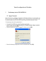
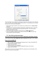
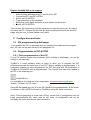
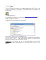
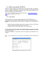
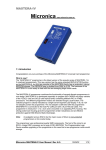
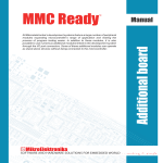
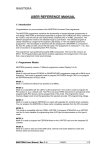
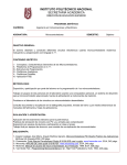
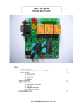
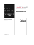
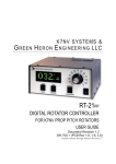
www.astrimage.org/pic-astro
Test's manual of PIC-ASTRO A1
Version 1.0
Summary
1 Preliminary tests of PIC-ASTRO A1...........................................................................3
1.1 Hyper Terminal....................................................................................................3
1.2 Test of the serial connections..............................................................................4
2 Configuration and tests .............................................................................................5
2.1 PIC programmed by Astrimage...........................................................................5
2.2 Programmation of PIC-ASTRO ..........................................................................5
2.2.1 First programmation of the PIC.....................................................................5
2.2.2 TinyBld..........................................................................................................6
2.3 Utilities for testing PIC_ASTRO A1.....................................................................7
2.3.1 Test_18f.hex..................................................................................................7
2.3.2 Test Vmax.....................................................................................................8
2.3.3 Calibration of µsteps.....................................................................................8
2.4 Software PIC-ASTRO..........................................................................................9
3 Configuration of PIC-ASTRO.....................................................................................9
3.1 Specifications of the mount.................................................................................9
3.2 Use of the command Zp....................................................................................10
3.3 Generate configuration file................................................................................10
4 Tests on the mount...................................................................................................10
4.1 Test for tracking sense......................................................................................10
4.2 Tests on Goto mode..........................................................................................11
www.astrimage.org/pic-astro
Page 2 sur 11
Tests & configuration of Pic-Astro
1
Preliminary tests of PIC-ASTRO A1
1.1 Hyper Terminal
Hyper Terminal is a software component of Windows allowing to communicate via
the serial port with PIC-ASTRO. Thanks to Hyper Terminal you can make all the tests
of communications with PIC-ASTRO but also interact with the software of tests.
It's necessary above all to parametrize it :
•
•
Connect PIC-ASTRO A1 to the PC with the serial cable.
Launch Hyper terminal: Start /Accessories /Communications /Hyper terminal.
Enter a name and click [OK].
Select the serial port where is plugged Pic-Astro and click [OK] :
1.
Enter the following configuration for the connection then click [OK] :
•
The connection is now configured, and Hyper Terminal is connected to the serial port
as the icon with a small hung up telephone indicates it. It is necessary now to modify
the local echo of the seized characters:
•
•
•
•
Disconnect Hyper Terminal of the serial port by clicking the icon of taken down
telephone
Go to the menu File/Properties/Parameters/Ascii Configuration Ascii/ Cross the
compartment " reproduce locally the entered characters ", then close all the
window by clicking on [OK]
Re-connect Hyper Terminal by clicking the icon of hung up telephone
Save the connection which you can use henceforth all the time for your long
communications with PIC-ASTRO !
1.2 Test of the serial connections
This test has to be made only if you notice a dysfunction with Hyper-terminal.
These tests must be made without the microcontroller PIC settled in PIC-ASTRO.
Remove first the MAX-232:
•
•
•
•
•
•
Make a strapp (connect with a wire) between pines 7 and 8 of the MAX-232
Connect the PC and PIC-ASTRO
Switch on PIC-ASTRO
Type characters on the keyboard
Verify that each character typed is displayed 2 times on the screen.
Switch off PIC-ASTRO
This confirms the arrival of the signal RS-232 ( serial port) up to the borders of the
MAX-232, and the null serial cable.
Replace the MAX-232 on its support:
•
•
•
•
•
•
Make a strapp between pines 17 and 18 of the PIC
Connect the PC and PIC-ASTRO
Switch on PIC-ASTRO
Type characters on the keyboard
Verify that every typed character is twice shown on the screen
Switch off PIC-ASTRO
This confirms the functioning of all the transmission chain by serial port : the signal
arrives to the PIC. If that is not the case but that everything worked in the previous
stage, are you sure, to have indeed a null cable.
2 Configuration and tests
2.1 PIC programmed by Astrimage
If you ordered the PIC to Astrimage this one contains the loader and the program
test_18F you can go then directly to the paragraph 2.3.
2.2 Programmation of PIC-ASTRO
2.2.1 First programmation of the PIC
If your PIC already contain the bootloader (PICs ordered to Astrimage), you can go
directly to the next step.
TinyBld is a small software which is going to allow you to program the PIC
µControllor through the serial port of your PC without needing a programmator. It is
necessary however to have programmed the PIC first time with the bootloader of
TinyBld for PIC18F252 with a programmator. The .hex file that has to be loaded in
the PIC is the following one :
tinybld18f.hex
It is available on the Web site of the association: www.astrimage.org/pic-astro
chapter " Software for PIC-astro ".
Once this file loaded once for all in the PIC thanks to the programmator, all the loads
of software in PIC-ASTRO will remit to TinyBld by using the serial connection.
Note: if the programming is made with ICProg, certain bits of configuration are not
being programmable the value read by the fuses of configuration will not be
inevitably the same that the one who was written.
2.2.2 TinyBld
The use of TinyBld is very simple, you just have to download the file ZIP and to unzip
it once for all in a folder of your computer. The launch is made by executing the file
tinybldWin.exe.
TinyBldWin.zip
It is available on the Web site of the association: www.astrimage.org/pic-astro
chapter " Software for PIC-astro ".
TinyBld opens already configured for PIC-ASTRO :
Dont' forget to check the speed rate to 9600 bauds.
To load a file in PIC-ASTRO, You just have to select it by clicking on [Browse] and to
click on « Write Flash ». A small moment before switching on PIC-ASTRO. A
message will confirm you the success of the operation.
ATTENTION if the program test_18F was previously loaded in the PIC it is
necessary to switch off PIC-ASTRO, to click "Write Flash" then to switch on PICASTRO.
2.3 Utilities for testing PIC_ASTRO A1
Utilities for testing following are all functionning on the same principle : you'll have to
load the .hex file, containing the utility of test to execute in PIC-ASTRO with the
software TinyBldWin, then launch a connexion Hyper Terminal that will allow you to
follow the indications given by PIC-ASTRO.
There are all available on the web site of the association : www.astrimage.org/picastro chapter « softwares for Pic-astro »
2.3.1 Test_18f.hex
This utility allows you to test the elementary functions of PIC-ASTRO. Launch
Hyperterminal and make a reset of PIC-ASTRO. Then follow the instructions shown
in Hyperterminal, when press one touch is asked, it is about a key of the keyboard of
the PC :
•
•
Buttons of the hand controller: maneuver the various elements of the PAD and
verify in Hyperterminal that this element is very active.
Rotation of motors: tests by pressing on a key of the keyboard
In case of dysfunction of one of the organs, the first elements who has to be verified
are the tracks of circuits and welds. The software having been tested the problem
can be only hardware.
In case of not display in Hyperterminal, make the preliminary tests described in the
chapter 1.
Note : If your ordered your PIC to Astrimage, Test_18f.hex is already loaded in the
PIC.
2.3.2 Test Vmax
This utility allows you to vary the speed of your motor through the control knob
potentiometer of the PAD. The threshold values obtained were eligible for the
following and are given in μs.
Before switching on PIC-astro, you must positionned the potentiometer to maximum.
After switch on you must reduced potentiometer to speed up the motor. In
Hyperterminal you can read the μstep period, from half step to step, this value is
given in μs.
2.3.3 Calibration of µsteps
Please read the document about this on our website www.astrimage.org .
2.4 Software PIC-ASTRO
It is now necessary to load in PIC-ASTRO the software tools to make it work.
Versions of the file containing this software is available on www.astrimage.org/picastro section « Software for Pic-Astro ».
This software is downloadable into the PIC with TinyBldWin following the procedure
described in paragraph 2.2.2.
This software has to be updated with each new version.
To check the good dialogue with a new version of software :
•
•
•
Connect the PC to PIC-ASTRO
Switch on PIC-ASTRO
in Hyperterminal type CTRL<F>
PIC-ASTRO must answer by character « P », the logic part of PIC-ASTRO is
running.
3
Configuration of PIC-ASTRO
3.1 Specifications of the mount
PIC-ASTRO fits all German equatorial mounts whose motorisation is provided by
stepper motors. It is very important for the configuration of PIC-ASTRO to know
exactly the characteristics of these :
•
•
•
Number of steps per revolution of stepper motors
Gear ratios of motorcycle gear if there is one. These may be different on the
axis of right ascension and declination axis.
Gear ratio of the helical worm gear
In order to deduce the key parameter of the system configuration: the number of
steps, half-step or micro-step to be made by the motors to make a worm turn, or a
displacement of 10 arc minutes in many cases, and the subtleties that may exist
where the motor and transmission of the two axes are not strictly identical.
These features will be input parameters of the configuration software, and if they are
unknown or uncertain, a command LX200 specific on PIC-ASTRO will enable you to
find with certainty.
The Excel file below shows the settings for several common mounts and allows you
to redo the calculation if necessary for yours :
Mounts.xls
3.2 Use of the command Zp
The command Zp allows to move the motor connected to the DEC pin of PIC
-ASTRO for a certain number of steps. It is very easy to use this command, simply
connect HyperTerminal to PIC-ASTRO as usual way, then type the following
command for example (The upper / lower case must be respected):
:Zp 92160#
The motor will then move for 92160 μsteps to the speed selected by the button of the
PAD. This command is essential to verify or determine the parameters of the mount.
In the case of a mount EQ-5/SP-DX this allows to verify that 92160 μsteps is the
good value to turn the worm for a lap. This parameter is essential for the
configuration of PIC-ASTRO. Ideally this command is used on several laps in order to
minimize errors due plays and read errors, for example, you can check that the worm
does 10 laps for 921 600μpas.
3.3 Generate configuration file
The configuration of PIC-ASTRO is generated by a small software on your PC.
A configuration file will be generated and you have to transfer through TinyBld in the
usual way.
The software for settings and his user's manual are available on www.astrimage.org/
pic-astro section « software for Pic-Astro ».
4 Tests on the mount
4.1 Test for tracking sense
First, make sure the motor is running RA in the right direction, if this is not the case,
reverse the connections 1-4 or 2-3 of the motor. Then you can make a visual test
with a good station, you can check that for a star it does not leave the field even at
high magnification. Be careful not to confuse a tracking error with a bad station or a
periodic error.
4.2 Tests on Goto mode
To validate the proper functioning of PIC-ASTRO, you can test Goto in "empty" mode
by helping with you coordinate rings of your mount. To do that do the classic method
for Goto (see manual) and make sure that the mount is moving from the right angle
on each axis. Beware of inaccuracies caused by poor quality circles coordinates!
Mechanical errors too high and / or poorly compensated may also be important
sources of error.
If PIC-ASTRO tip objects with far too little or too much travel, check the configuration
settings: are you sure the number of teeth on your sprocket? The gear ratio of your
gear or your pulleys?
Congratulations, you arrived at the end of your sentences, now it only remains
to fully exploit PIC-ASTRO: Goto, autoguiding ...
You can refer to the documentation for using Pic-Astro available on
www.astrimage.org / pic astro section "documentation."