1
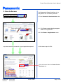
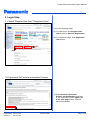
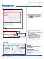
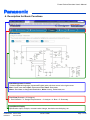
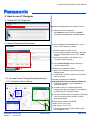
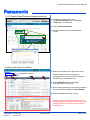
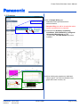
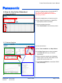
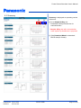
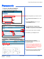
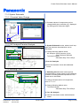
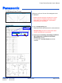
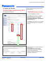
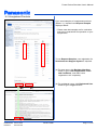
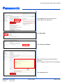
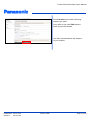
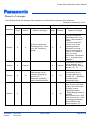
Power Device Simulator User's Manual Established: 2012-12-20 Revised: 2013-01-25 PP1201-020E Page 1 of 23 Power Device Simulator User's Manual Contents 1. Introduction ............................................................................................................. 3 1.1 Overview .............................................................................................................................................. 3 1.2 Hardware Requirement and Support ................................................................................................... 3 1.3 Usage Note .......................................................................................................................................... 3 2. How to Access ........................................................................................................ 4 3. Login Step ............................................................................................................... 5 3.1 Select "Register New User"/"Registered User" ................................................................................. 3.2 Agreement for Personal Information Practice .................................................................................... 3.3 Account Registration ......................................................................................................................... 3.4 Login .................................................................................................................................................. 3.5 Tool Menu .......................................................................................................................................... 5 5 6 6 6 4. Description for Basic Functions ........................................................................... 7 5. How to Use IC Designer ......................................................................................... 8 5.1 Select DC-DC Regulator ................................................................................................................... 5.2 Enter Operational Parameters .......................................................................................................... 5.3 Constant Value Change/Operating Analysis .................................................................................... 5.3.1 Constant Value Change .............................................................................................................. 5.3.2 Steady-State/Transient Analysis/Start-Up ................................................................................... 5.4 BOM List/Online Purchase ............................................................................................................... 5.5 Summary .......................................................................................................................................... 8 8 8 8 9 9 10 6. How to Use Active Datasheet ............................................................................... 11 6.1 Select MOSFET ............................................................................................................................... 11 6.2 Various Analysis .............................................................................................................................. 11 6.3 Summary .......................................................................................................................................... 12 7. How to Use Buck Analyzer ................................................................................... 13 7.1 Enter Operational Parameters .......................................................................................................... 7.2 Select MOSFET ............................................................................................................................... 7.3 System Schematic/Switching Circuit ................................................................................................ 7.3.1 System Schematic ...................................................................................................................... 7.3.1.1 Constant Value Change ....................................................................................................... 7.3.1.2 AC Analysis/Transient Analysis ............................................................................................. 7.3.2 Switching Circuit ......................................................................................................................... 7.4 Efficiency/Loss Curves ..................................................................................................................... 7.5 Summary .......................................................................................................................................... 13 13 13 14 14 14 14 15 15 8. Inquiry for Sample (Until the Beginning of February, 2013) ............................. 16 8.1 Registered Products ......................................................................................................................... 16 8.2 Unregistered Products ...................................................................................................................... 17 Established: 2012-12-20 Revised: 2013-01-25 PP1201-020E Page 2 of 23 Power Device Simulator User's Manual 1. Introduction 1.1 Overview Power Device Simulator (tentative name) is a simulator (charge-free) utilizing DC-DC regulator and switching MOSFET manufactured by Panasonic easily on the Web. Power Device Simulator consists of three simulation tools, IC Designer for DC-DC regulator, and Active Datasheet, Buck Analyzer for MOSFET. With support for specification verification, operating analysis, creating BOM list, and online purchase, Power Device Simulator alleviates customers' burden for product selection. 1.2 Hardware Requirements and Support Power Device Simulator supports for Japanese and English Following hardware requirements are recommended. Please confirm them beforehand, otherwise the abnormal operation or the unexpected error may occur depending on customers' environment. OS: Windows 7, Windows Vista, Windows XP, Mac OS X Browser: Internet Explorer 9, Google Chrome 23, Firefox 16.0.2 and their previous versions If you have questions regarding Power Device Simulator besides errors in operation etc., please call our sales representatives or visit following Website. Semiconductor Business Unit, Industrial Devices Company, Panasonic Corporation URL: http://www.semicon.panasonic.co.jp/en/ 1.3 Usage Note If Security Warning is displayed when using Internet Explorer (IE), click No (N) button. Though simulation results of Power Device Simulator are verified consistency with observation results using our evaluation board, they may be different from actual results due to the difference of boards, mounting conditions, evaluation environments, etc. If this simulator is left for 30 minutes without operation, "Timeout Error" occurs and re-login is needed. Specifications on this site are subject to change without prior notice. We may not meet your request for sample purchases from this site due to changes in inventory status of products at each distributor. Established: 2012-12-20 Revised: 2013-01-25 PP1201-020E Page 3 of 23 Power Device Simulator User's Manual 2. How to Access Panasonic Semiconductor Visit Panasonic Power Solution site by using either one of following methods. Search a. From Panasonic Semiconductors site http://www.semicon.panasonic.co.jp/en/ a-1 a-2 http://www.semicon.panasonic.co.jp/en/applications/power/ a-1. Click Power supply design support tools in rolling banners. a-2. Click Power in Applications menu. b. With direct input for URL. Click this banner linked to Power Device Simulator site. Established: 2012-12-20 Revised: 2013-01-25 PP1201-020E Page 4 of 23 Power Device Simulator User's Manual 3. Login Step 3.1 Select "Register New User"/"Registered User" Follow the following steps. (a) For new users, click Register New User button for Account Registration. (b) For registered users, click Registered User button. (b) (a) 3.2 Agreement for Personal Information Practice ① Read Personal Information Practice on the Website completely. If you agree with it, click I agree; go to the next page button. This tool becomes available. ① Established: 2012-12-20 Revised: 2013-01-25 PP1201-020E Page 5 of 23 Power Device Simulator User's Manual 3.3 Account Registration ② ② Enter your email address, password, name, company name, country, etc. Click Register button with Terms of Use checked. 3.4 Login For registered users, Login window is displayed. ③ ③ Enter your email address and password. Click Login button. * If you click Login button with Remember me checked, you don't need to enter them from next time. * If you forget your password, click Forgot password button. Your password is sent to your email address. 3.5 Tool Menu Tool menu is displayed after login. Select the simulation tool you use. IC Designer Power supply circuit simulation using DC-DC regulator Active Datasheet Device simulation using MOSFET Buck Analyzer Power supply circuit simulation using MOSFET Established: 2012-12-20 Revised: 2013-01-25 PP1201-020E Page 6 of 23 Power Device Simulator User's Manual 4. Description for Basic Functions Data Management Function * Select supported language (Japanese/English) with pull-down menu in the right corner. New: Create new data, Open: Open saved data, Save: Save data, Share: Send data to designated destination, More: History, Delete data, etc. Tool Flow (Example: IC Designer) 1. Part Selection → 2. Design Requirements → 3. Analyze → 4. Bom → 5. Summary Input/Result Display Specification input, analysis, constant value change, simulation result display, etc. Established: 2012-12-20 Revised: 2013-01-25 PP1201-020E Page 7 of 23 Power Device Simulator User's Manual 5. How to use IC Designer 5.1 Select DC-DC Regulator Select the application you intend to use for. ① Select the DC-DC regulator. Click Select button on the left of Part #. * To download datasheets, click Info button. ① 5.2 Enter Operational Parameters ② Enter Operational Parameters (Vin, Vout, Iout(*), SW Frequency, Mode). * Input the maximum value to Iout. In the operating analysis simulation, the load current is assumed as 50% to 75% (RMS) of Iout. (For more information, see Section 5.3.1, “Constant Value Change.”) ③ Click Create Design button to display a recommended circuit. ② ③ Description for Operation Mode Skip mode: Efficiency improvement mode with light load FCCM mode: Forced continuous mode with frequency fixed. 5.3 Constant Value Change/Operating Analysis 5.3.1 Constant Value Change ⑤´ ④ Following analyses are available. Steady-State/Transient Analysis/Start-Up * Frequency analysis is also available for AN33XXX series. ④ Constant values of components can be changed with pop-up window (④´) displayed by clicking each component figure. ⑤ The Start Current and Final Current of [LOAD] refer to the load current (ILOAD) in each operating analysis. ④´ ⑤ 【Initial setting values of ILOAD】 Start Current: Iout x 50% Final Current: Iout x 75% To change parameters, click [LOAD] on the circuit diagram. (⑤´) Established: 2012-12-20 Revised: 2013-01-25 PP1201-020E Page 8 of 23 Power Device Simulator User's Manual 5.3.2 Steady-State/Transient Analysis/Start-Up ⑥ Change Simulation Stop Time. Transient Analysis: 200 µs (default) Start-Up: 4 ms (default) ⑦ Start Transient Analysis. ⑧ View simulation results with dedicated viewer. ⑥ ⑦ ⑧ 5.4 Bom List/Online Purchase ⑨ Select the distributor with pull-down menu. ⑨ Distributor Select ⑫ ⑩ ⑪ * Please note that online purchase for semiconductor products (DC-DC regulator, MOSFET) is not available now. ⑩ Click CHECKOUT button to display inventory status of products. ⑪ When setting quantity for lump-sum purchase, the unit prices are displayed (Price Break). ⑫ Download BOM list (Excel format). * Online purchase for DC-DC regulator will be available after the beginning of February, 2013. (Online purchase for passive components is available now.) Established: 2012-12-20 Revised: 2013-01-25 PP1201-020E Page 9 of 23 Power Device Simulator User's Manual 5.5 Summary ⑬ Go to Sample & Buy site. * Dedicated online purchase site for semiconductors * Sample & Buy site will be closed after sales system by distributors is prepared. ⑬ ⑭ Download the Summary (Operating Conditions, Bill of Materials, Configured Schematic, Waveforms) as PDF. * To open PDF, Acrobat Reader should be installed. ⑭ ⑮ When clicking the graph area, dedicated viewer opens. You can view details of the graph with zoom function, etc. ⑮ Established: 2012-12-20 Revised: 2013-01-25 PP1201-020E Page 10 of 23 Power Device Simulator User's Manual Verify the characteristics of single MOSFET. You can evaluate with the test circuit described in the datasheet at customers' operating condition. 6. How to Use Active Datasheet 6.1 Select MOSFET Select the application you intend to use for. ① ① Enter Search Parameters for MOSFETs. Appropriate products are listed. ② Select the desired product. Click Part Number of the desired product. ② 6.2 Various Analysis ⑦ ③ Click the test item. ⑤' ⑥ ③ ④ ④ Enter Test conditions and Step Values. ⑤ Click Run Test button to start simulation. (Click Run all button (⑤') to start all simulations.) ⑥ When clicking the graph area, dedicated viewer opens. You can view details of the graph with zoom function, etc. ⑤ ⑦ Click Download Model to download SPICE data (lib format). Established: 2012-12-20 Revised: 2013-01-25 PP1201-020E Page 11 of 23 Power Device Simulator User's Manual 6.3 Summary ⑧ ⑦' Summary is displayed as operating results of this tool. ⑧ Go to Sample & Buy site. * Dedicated online purchase site for semiconductors * Sample & Buy site will be closed after sales system by distributors is prepared. ⑦' Click Download Model to download SPICE data (lib format). Established: 2012-12-20 Revised: 2013-01-25 PP1201-020E Page 12 of 23 Power Device Simulator User's Manual 7. How to Use Buck Analyzer 7.1 Enter Operational Parameters Select the application you intend to use for. ① Enter Operational Parameters (Vin, Vout, Iout). ① ② Click Select MOSFETs button to go to Select MOSFET window. ② 7.2 Select MOSFET ③ Select Part Number of Upper/Lower MOSFETs from parts list. Search refinement for single or dual products is also available. ⑤ ④ Prefix search of part number is enabled. ④ ⑤ Click Next to go to Analyze window. ④ ③ ③ ⑤ 7.3 System Schematic/Switching Circuit Following analyses are available. AC Analysis (System Schematic only) Transient Analysis ⑥ * Whole-circuit loop gain characteristics can be simulated in System Schematic mode. Switching characteristics including parasitic impedance of the board can be simulated in Switching Circuit mode. ⑥ Click this tab menu to select the analysis for System Schematic/Switching Circuit. Established: 2012-12-20 Revised: 2013-01-25 PP1201-020E Page 13 of 23 Power Device Simulator User's Manual 7.3.1 System Schematic 7.3.1.1 Constant Value Change ⑦ Constant values of components can be changed with pop-up window (⑦') displayed by clicking each component figure. ⑦' ⑦ 7.3.1.2 AC Analysis/Transient Analysis In System Schematic mode, whole-circuit loop gain and transient characteristics can be simulated. ⑧ ⑧ Change following default values. AC Analysis: Start Frequency 10 Hz Stop Frequency 500 kHz Transient Analysis: Simulation Stop Time 100 µs ⑨ ⑩ ⑨Start AC Analysis. ⑩View the simulation result with dedicated viewer. 7.3.2 Switching Circuit ⑪ ⑫ ⑬ In Switching Circuit mode, load response characteristics by power supply circuit switching operation including parasitic impedance of the board can be simulated. To change constant values of components, refer to "7.3.1.1". ⑪ Change following default value. Transient Analysis: Simulation Stop Time 250 µs ⑫ Start AC Analysis. ⑬ View the simulation results with dedicated viewer. Established: 2012-12-20 Revised: 2013-01-25 PP1201-020E Page 14 of 23 Power Device Simulator User's Manual 7.4 Efficiency/Loss Curves Efficiency and Loss Curves of the designed circuit is displayed. * Please note that parasitic impedance or losses due to the jitter of switching waveform, which really exist, are not taken into consideration in this efficiency calculation. 7.5 Summary ⑭ Go to Sample & Buy site. * Dedicated online purchase site for semiconductors * Sample & Buy site will be closed after sales system by distributors is prepared. ⑭ Established: 2012-12-20 Revised: 2013-01-25 ⑮ ⑮ Download the Summary (Operating Conditions, Bill of Materials, Configured Schematic, Waveforms) as PDF. * To open PDF, Acrobat Reader should be installed. PP1201-020E Page 15 of 23 Power Device Simulator User's Manual 8. Inquiry for Sample (Until the Beginning of February, 2013) This is dedicated online purchase site for semiconductors. * Sample & Buy site will be closed after sales system by distributors is prepared. 8.1 Registered Products ① Check the Status of products. If the Status of the product is "Available", sample purchase from the distributor authorized by Panasonic is available. Click Registered Part No. to go to Search Parts Inventory site. ① ① If the Status of the product is not "Available", see the following page, "8.2 Unregistered Product". Sample purchases from listed distributors are available. Click the Panasonic Parts Number corresponding to the desired distributor to go to online purchase site. (Quantity of samples for dealing varies according to distributors.) Established: 2012-12-20 Revised: 2013-01-25 PP1201-020E Page 16 of 23 Power Device Simulator User's Manual 8.2 Unregistered Products If you need samples of unregistered products (Status: *1), request from Request Samples displayed below. * Please note that samples are for evaluation and are not guaranteed for operation on your equipments. ① ① To use Request Samples, user registration for Semiconductor Support System is required. (a) For new users, click Register New User button to go to User Registration Terms and Conditions, and read "user's registration rule" completely. (b) For registered users, click Registered User button to go to Login window. (a) Established: 2012-12-20 Revised: 2013-01-25 (b) PP1201-020E Page 17 of 23 Power Device Simulator User's Manual Click Login button after entering your email address and password. Click New Q&A. Click Inquiry for Sample. Enter the title and the main text like the example. (Do not forget to write Part No. and quantity.) Click Confirm button. Established: 2012-12-20 Revised: 2013-01-25 PP1201-020E Page 18 of 23 Power Device Simulator User's Manual Click Transmit button after confirming contents you enter. If you want to edit, click Edit button to return to previous window. Our sales representatives will respond to your request. Established: 2012-12-20 Revised: 2013-01-25 PP1201-020E Page 19 of 23 Power Device Simulator User's Manual Record of changes The following shows the changes in the publication of Power Device Simulator User’s Manual. Revised on January 25, 2013 Previous Edition (1st Edition) Definition Change Addition Change Addition Page 8 8 8 8 Established: 2012-12-20 Revised: 2013-01-25 Section 5 Details of Changes ② Enter Operational Parameters (Vin, Vout, Iout, SW Frequency, Mode). Capture 18 ④ Constant values of components can be changed with pop-up window (⑤´) displayed by clicking each component figure. PP1201-020E New Edition (2nd Edition) Page 8 8 8 8 Section Details of Changes 5 ② Enter Operational Parameters (Vin, Vout, Iout(*), SW Frequency, Mode). * Input the maximum value to Iout. In the operating analysis simulation, the load current is assumed as 50% to 75% (RMS) of Iout. (For more information, see Section 5.3.1, “Constant Value Change.”) Capture Comments of [LOAD] in circuit diagram, and Constant Value Change window. (⑤,⑤´) 23 ④ Constant values of components can be changed with pop-up window (④´) displayed by clicking each component figure. 26 ⑤ The Start Current and Final Current of [LOAD] refer to the load current (ILOAD) in each operating analysis. 【Initial setting values of ILOAD】 Start Current: Iout x 50% Final Current: Iout x 75% To change parameters, click [LOAD] on the circuit diagram. (⑤´) Page 20 of 23 Power Device Simulator User's Manual Inquiries If you have questions regarding operating methods for Power Device Simulator described in this manual, please visit the following URL. URL: https://www.semicon.panasonic.co.jp/semi-spt/general/?lang=en To new customers: Please register your account prior to login. After login, click "WebSIM" in Semiconductor Support System site, click "Inquiry", click "New Q&A" of "Related Menu", and click "Inquiry for operation procedure". Pub. No. PP1201-020E Power Device Simulator User’s Manual January 2013 2.0 Edition Issued by Panasonic Corporation © Panasonic Corporation 2012-2013 Established: 2012-12-20 Revised: 2013-01-25 PP1201-020E Page 21 of 23