1
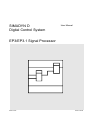
SIMADYN D
Digital Control System
User Manual
EP3/EP3.1 Signal Processor
Edition 03.98
DK-No. 243261
User Manual, EP3/EP3.1 Signal Processor Module
Edition
Status
1
EP3/EP3.1 Signal Processor Module
02.96
2
EP3/EP3.1 Signal Processor Module
03.98
Weitergabe sowie Vervielfältigung dieser Unterlage, Verwertung und
Mitteilung ihres Inhalts nicht gestattet, soweit nicht ausdrücklich
zugestanden. Zuwiderhandlungen verpflichten zu Schadenersatz.
Alle Rechte vorbehalten, insbesondere für den Fall der
Patenterteilung oder GM-Eintragung.
Copying of this document and giving it to others and the use or
communication of the contents thereof is forbidden without express
authority. Offenders are liable to the payment of damages. All rights
are reserved in the event of the grant of a patent or the registration of
a utility model or design.
Wir haben den Inhalt der Druckschrift auf Übereinstimmung mit der
beschriebenen Hard- und Software überprüft. Dennoch können
Abweichungen nicht ausgeschlossen werden, so daß wir für die
vollständige Übereinstimmung keine Garantie übernehmen. Die
Angaben in dieser Druckschrift werden jedoch regelmäßig überprüft
und notwendige Korrekturen sind in den nachfolgenden Auflagen
enthalten. Für Verbesserungsvorschläge sind wir dankbar.
We have checked the contents of this Manual to ensure that they
coincide with the described hardware and software. However,
deviations cannot be completely ruled-out, so we cannot guarantee
complete conformance. However, the information in this document is
regularly checked and the necessary corrections included in
subsequent editions. We are thankful for any recommendations or
suggestions.
Contents
Contents
Warning information................................ ................................ ................................ ...................... 1
1. Ordering data................................ ................................ ................................ ............................ 3
2. Function description................................ ................................ ................................ .................. 3
3. Board design................................ ................................ ................................ ............................. 3
4. Application information................................ ................................ ................................ .............. 4
4.1. Plug-in technology cards................................ ................................ ............................ 4
4.2. Configuring ................................ ................................ ................................ ................ 6
4.3. Commissioning ................................ ................................ ................................ .......... 6
5. Technical data................................ ................................ ................................ ........................... 7
5.1. General information ................................ ................................ ................................ ... 7
5.2. Current drain................................ ................................ ................................ .............. 7
5.3. Binary inputs (connector X6)................................ ................................ ...................... 7
5.4. Binary outputs (connector X6)................................ ................................ .................... 7
5.5. Analog outputs (connector X7)................................ ................................ ................... 8
6. Connector assignments................................ ................................ ................................ ............. 8
6.1. Connector X5................................ ................................ ................................ ............. 8
6.2. Connector X6................................ ................................ ................................ ............. 8
6.3. Connector X7................................ ................................ ................................ ............. 8
7. Supplementary components................................ ................................ ................................ ...... 9
8. ESD instructions................................ ................................ ................................ ........................ 10
Siemens AG Dk-No. 243261
SIMADYN D Hardware User Manual
Edition 03.98
3
Warning information
4
Edition 03.98
Siemens AG Dk-No. 243261
SIMADYN D Hardware User Manual
Contents
NOTE!
The information in this Manual does not purport to cover all details or variations in equipment, nor to provide
for every possible contingency to be met in connection with installation, operation or maintenance.
Should further information be desired or should particular problems arise which are not covered sufficiently for
the purchaser’s purposes, please contact your local Siemens office.
Further, the contents of this Manual shall not become a part of or modify any prior or existing agreement,
committment or relationship. The sales contract contains the entire obligation of Siemens. The warranty
contained in the contract between the parties is the sole warranty of Siemens. Any statements contained
herein do not create new warranties nor modify the existing warranty.
Warning information
WARNING!
Electrical equipment has components which are at dangerous voltage levels.
If these instructions are not strictly adhered to, this can result in severe bodily
injury and material damage.
Only appropriately qualified personnel may work on this equipment or in its
vicinity.
This personnel must be completely knowledgeable about all the warnings and
service measures according to this User Manual.
The successful and safe operation of this equipment is dependent on proper
handling, installation, operation and maintenance.
Siemens AG Dk-No. 243261
SIMADYN D Hardware User Manual
Edition 03.98
1
Warning information
Definitions
*
QUALIFIED PERSONNEL
*
DANGER
*
WARNING
*
CAUTION
*
NOTE
For the purpose of this User Manual and product labels, a „Qualified person“ is someone who is familiar with the
installation, mounting, start-up and operation of the equipment and the hazards involved. He or she must have
the following qualifications:
1. Trained and authorized to energize, de-energize, clear, ground and tag circuits and equipment in accordance
with established safety procedures.
2. Trained in the proper care and use of protective equipment in accordance with established safety
procedures.
3. Trained in rendering first aid.
For the purpose of this User Manual and product labels, „Danger“ indicates death, severe personal injury and/or
substantial property damage will result if proper precautions are not taken.
For the purpose of this User Manual and product labels, „Warning“ indicates death, severe personal injury or
property damage can result if proper precautions are not taken.
For the purpose of this User Manual and product labels, „Caution“ indicates that minor personal injury or
material damage can result if proper precautions are not taken.
For the purpose of this User Manual, „Note“ indicates information about the product or the respective part of the
User Manual which is essential to highlight.
CAUTION!
This board contains components which can be destroyed by electrostatic
discharge. Prior to touching any electronics board, your body must be electrically
discharged. This can be simply done by touching a conductive, grounded object
immediately beforehand (e.g. bare metal cabinet components, socket protective
conductor contact).
WARNING!
Hazardous voltages are present in this electrical equipment during operation.
Non-observance of the safety instructions can result in severe personal injury or
property damage.
It is especially important that the warning information in all of the relevant
Operating Instructions are strictly observed.
2
Edition 03.98
Siemens AG Dk-No. 243261
SIMADYN D Hardware User Manual
Contents
1. Ordering data
EP3: 6DD 1645- 0AE0
EP3.1: 6DD 1645- 0AE1
2. Function description
The SIMADYN D system is especially suitable for especially fast closed-loop control and arithmetic
operations, special converter-related functions, including gating unit and for fast analog signal
processing (digital filter).
The EP3/3.1 has a DSP56002 signal processor, whose functions can be configured using STRUC, as
well as interfaces to plug-in technology cards, with which the peripheral hardware can be optimally
adapted to the particular task.
3. Board design
Width: 1 slot
X52: Connection for 2nd plug-in card
Memory Card interface
LED function display H10, H11
Acknowledge button S1
X2: L-bus connection
9-pin sub-D socket X5
service and diagnostics
15-pin micro sub-D socket X6
8 binary inputs, 4 binary outputs
X51:Connection for 1st plug-in card
20-core ribbon cable connector X7
8 analog outputs
*
*
*
*
*
*
*
DSP56002 signal processor with 54 MHz clock frequency for EP3
DSP56002 signal processor with 66 MHz clock frequency for EP3.1
128k x 24 bit working memory
3 LCAs XC4013 for interrupt processing, signal pre-processing and fast logic functions
(gating unit or similar)
Serial Communication Controller 85C30 for serial communications
(2 channels for 2 plug-in cards)
Communications via L bus via 4k x 16 bit dual port RAM
Watchdog for fault identification and processor monitoring withdraws *RDYIN, if the DSP
no longer reads or writes (*RDYIN is accessed at MM3, MM4)
Siemens AG Dk-No. 243261
SIMADYN D Hardware User Manual
Edition 03.98
3
Application information
4. Application information
For perfect functioning, the board must be screwed-into the subrack (also during start-up).
4.1. Plug-in technology cards
Plug-in technology cards are required in order to fully-utilize the special characteristics and features
of the EP3/3.1. These provide the hardware for the particular application (e.g. fast and accurate
analog inputs for digital filters, firing pulse output for the gating unit).
An EP3/3.1 can be equipped with a max. of 2 plug-in cards. They are screwed to one another and to
the EP3/3.1 using distance studs, to form a single mechanical unit. An LCA design, tailored to the
particular plug-in card belongs to each card, as a plug-in card is connected to the DSP via an LCA on
the EP3/3.1. A function block, which runs on the DSP, communicates with the LCA, and the LCA then
controls the hardware on the plug-in card. Further, the LCA can be used to implement many logic
functions thus relieving the DSP.
S
Plug-in card 2
B
S
Plug-in card 1
Adapter
B
EP3
DSP
L bus
LCA B LCA C
The diagram shows that plug-in card 1 is controlled from LCA-B, and plug-in card 2, which is
connected to EP3/3.1 via an adapter, from LCA-C.
The configuration for an LCA is stored in a file, which is linked with it, when the DSP program is
generated. The DSP then configures the LCA for the particular application when it runs-up.
Presently, the following plug-in cards and associated LCA designs and function blocks are available:
4
Edition 03.98
Siemens AG Dk-No. 243261
SIMADYN D Hardware User Manual
Contents
IM1:
9 analog inputs, manual adjustment, manual setting of the
limiting frequency
16 binary inputs and 16 binary outputs, floating (electrically
isolated), no serial interface
Can only be used as the 1st plug-in card
Width: 1 slot
With LCA design and function blocks for analog input and binary
I/O
IT1:
9 analog inputs, manual adjustment, manual setting of the
limiting frequency
16 pulse outputs, non-floating (no electrical isolation) with a readback device for short-circuit identification
1 analog output for pulse ????
No serial interface SS
Can only be used as the 1st plug-in card
Width: 1 slot
With LCA designs and function blocks for analog input and for
various gating units
Siemens AG Dk-No. 243261
SIMADYN D Hardware User Manual
IM3:
9 analog inputs, automatic adjustment, software setting of the
limiting frequency
16 binary inputs and 16 binary outputs, floating (with electrical
isolation)
Serial interface V.24 can be used depending on the function
block
Zero crossover sensing for phase- and phase-to-phase voltages
Width: 1 slot
With LCA design and function blocks for analog input and binary
I/O, extinction angle measurement, HGÜ-DUST
IO3:
For optimal signal transfer
10 fiber-optic connections with optical/electrical converters
10 analog outputs
10 optical channels can be evaluated on which laser-modulated
telegrams with measured values can be transferred, output at
analog outputs and at EP, only in conjunction with a special laser
board and special measured value transducer
Width: 2 slots
with LCA design and function block
ID3:
Only in conjunction with IO3, received data is transferred to
additional EP3/3.1 without D/A- and A/D conversion.
Edition 03.98
5
Application information
4.2. Configuring
*
*
*
*
*
*
*
*
*
which
Operation with P16- and/or P32 modules
Communications with PM via communication blocks
Initialization- and communication FBs included in the standard SIMADYN D library
7 different sampling times, 0.1 ms to 5 s
per sampling time, 1 function package
21 interrupt events, 7 special interrupts via interrupt controller and operating system
1 free interrupt input on the DSP for special applications
Number of function blocks is dependent on the computation time and sampling time
(e.g. computation time for sophisticated closed-loop controls and gating unit with
approx. 70 FBs: 100 µs)
Configuring and documentation under STRUC G with special user function block library,
includes the FBs for the EP3/3.1
*
Compilation, linking and sub-module programming using the EP3/3.1 compiler EP3C,
additionally
required: Motorola DSP Development Software
*
MS5 and MS55 program memory modules for user- and system software
Concept
STRUC
editor and
compiler
User library with
standard EP3 FBs
INTEL-UDI-tools
FB generator
DSP-SW Motorola
New FB
Editing, compiling, library generation
Standard LCA design
Compilation, linking
EP3 compiler EP3C
DSP-SW Motorola
e.g. Viewlogic
XACT
New LCA design
Design input, compiling,
routing, converting
Memory Card
programming
EP3MC
Memory submodule
4.3. Commissioning
The EP3 IBS program (start-up program) is available for service and diagnostics. This program can
run on PCs or PGs under DOS or under a DOS shell under Windows.
Using this program, values and connections can be viewed, and temporarily or permanently modified.
Operator control is realized via a dialog window with FP name, FB name, connector. Further, the EP3
IBS program provides a hexadecimal monitor, which can be used to directly access the DSP memory
area.
The diagnostics interface of the EP3/3.1 is connector X5, a 9-pin sub-D socket connector.
Connecting cable
EP3/3.1 - PC/PG:
6
EP3/3.1
9-pin connector
2
at
3
at
5
at
Edition 03.98
PC/PG
9-pin socket
3
or
2
or
5
or
25-pin plug connector/socket
2
3
7
Siemens AG Dk-Nr. 243261
SIMADYN D Hardware User Manual
Technical data
5. Technical data
5.1. General information
INSULATION GROUP
AMBIENT TEMPERATURE
STORAGE TEMPERATURE
HUMIDITY CLASS acc. to DIN 40040
ALTITUDE RATING acc. to DIN 40040 S
DEGREE OF PROTECTION acc. to DIN 40050
MECHANICAL STRESSING
PACKAGING SYSTEM
DIMENSIONS
BOARD WIDTH
WEIGHT
acc. to VDE 0110
Degree of pollution 2
Insulating material class IIIa
0 to 55 oC
-40 to 70 oC
F
IP00
acc. to SN 29010 Class 12
ES 902 C
233:4mm*220mm
1 1/3 SPS = 1 slot width = 20.14mm
approx. 500g
5.2. Current drain
CURRENT DRAIN P5
CURRENT DRAIN P15
CURRENT DRAIN N15
1.0 A
55 mA
55 mA
+ plug-in card(s)
+ plug-in card(s) + load at X7
+ plug-in card(s) + load at X7
5.3. Binary inputs (connector X6)
No. type
Input voltage, nominal
for 0 signal
for 1 signal
Input current
for 0 signal
for 1 signal
Input time constant
8, non-floating
24 V nominal value
-1 V to + 6 V or open-circuit inputs
+13 V to +33 V
0 mA
3 mA typ.
1 µs
5.4. Binary outputs (connector X6)
No. type
Power supply voltage
nominal value
ripple
permissible range
briefly
Output current for a 1 signal
nominal value
permissible range
Short-circuit protection
Residual current
Signal level
for 0 signal
for 1 signal
Switching delay
Siemens AG Dk-No. 243261
SIMADYN D Hardware User Manual
4, non-floating
external
24 V
3.6 V
+20 V to +30 V incl. ripple
+ 35 V, max. 0.5 s
50 mA
0.2 mA to 50 mA
Electronic, thermal
20 µA for 0 signal
max. 3 V
Pext - 2.5 V
max. 15 µs
Edition 03.98
7
Connector assignments
5.5. Analog outputs (connector X7)
No., type
Output voltage range
Output current
Short-circuit current
Resolution
max. offset error
8, non-floating
-10 V to +10 V
max. 20 mA
max. 60 mA
12 bits incl. sign
+/-4 LSB
6. Connector assignments
6.1. Connector X5
9-pin sub-D socket connector, V.24 interface for diagnostics
Pin
1
2
3
4
5
Signal
Shield
RxD
TxD
GND
GND
6.2. Connector X6
15-pin micro-sub-D socket connector (three-row), binary inputs and outputs
Pin
1
2
3
4
5
Signal
Input 1
Input 2
Input 3
Input 4
P24
Pin
6
7
8
9
10
Signal
Input 5
Input 6
Input 7
Input 8
Mext
Pin
11
12
13
14
15
Signal
Output 5
Output 6
Output 7
Output 8
Minput
6.3. Connector X7
20-pin ribbon cable connector, analog outputs
Pin
1
2
3
4
5
6
7
8
8
Signal
Channel 1
GND
Channel 2
GND
Channel 3
GND
Channel 4
GND
Pin
9
10
11
12
13
14
15
16
Signal
Channel 5
GND
Channel 6
GND
Channel 7
GND
Channel 8
GND
Edition 03.98
Siemens AG Dk-Nr. 243261
SIMADYN D Hardware User Manual
Supplementary components
7. Supplementary components
Technology plug-in card IM1
Technology plug-in card IM3
Technology plug-in card IT1
Technology plug-in card IO3
Technology plug-in card ID3
with retaining screws/bolts
Item No. SE 113004.9101.00
presently being prepared
T89120-E3169
presently being prepared
presently being prepared
User libraries for STRUC with FBs for EP3
EP3 compiler EP3C
EP3 programming tool EP3MC
Diagnostics program EP3IBS
Motorola DSP Development Software
order from PSWE
contact ASI 1 G KT
In addition, to generate new function blocks:
INTEL-UDI tools
FB generator for STRUC and DSP
In addition, to generate new LCA designs:
CAD tools, e.g. Viewlogic
XILINX software to generate LCAs
Siemens AG Dk-No. 243261
SIMADYN D Hardware User Manual
Edition 03.98
9
ESD instructions
8. ESD instructions
Components which can be destroyed by electrostatic discharge (ESD)
Generally, electronic boards should only be touched when absolutely necessary.
The human body must be electrically discharged before touching an electronics board. This can be
simply done by touching a conductive, grounded object directly beforehand (e.g. bare metal cubicle
components, socket outlet protective conductor contact).
Boards may not come into contact with highly-insulating materials - e.g. plastic foils, insulated
desktops, articles of clothing manufactured from man-made fibers.
Boards may only be placed on conductive surfaces.
When soldering, the soldering iron tip must be grounded.
Boards and components should only be stored and transported in conductive packaging (e.g.
metalized plastic boxes, metal containers).
If the packing material is not conductive, the boards must be wrapped with a conductive packing
material, e.g. conductive foam rubber or household aluminum foil.
The necessary ESD protective measures are clearly shown in the following diagram.
a = Conductive floor surface
b = ESD table
c = ESD shoes
Seated
10
d = ESD overall
e = ESD chain
f = Cabinet ground connection
Standing
Edition 03.98
Standing / sitting
Siemens AG Dk-Nr. 243261
SIMADYN D Hardware User Manual
ESD instructions
Siemens AG Dk-No. 243261
SIMADYN D Hardware User Manual
Edition 03.98
11
ESD instructions
Drives and Standard Products
Variable-Speed Drives Division
Postfach 3269, D-91050 Erlangen
12
System-Based
Drive Technology
Edition 03.98
Siemens AG Dk-Nr. 243261
SIMADYN D Hardware User Manual