1
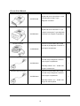
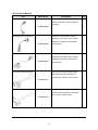
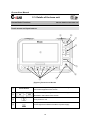
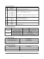
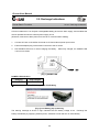
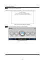
G-scan User Manual Contents Chapter 1. Getting Started with G-Scan 3 Read me first 4 Introduction to G-Scan 5 Safety Warnings and Cautions 6 Warnings for environment protection 8 Chapter 2. G-Scan Basic Functions 10 Specifications 11 Parts and Components 12 Details of the base unit 19 Power supply to G-Scan 22 Recharge Indications 25 Connecting with the car 26 Power On/Off 28 Chapter 3. G-Scan Basic Operations 29 Main menu and basic tools 30 Flight Recording 35 OBD-II and EOBD 38 Vehicle Diagnosis 44 Configuration 45 Om-Screen User’s Guide 56 1 G-scan User Manual Chapter 4. G-Scan PC Utility Software 57 Installation and Removal 58 Main menu 64 Recorded Data Viewer 66 Captured Screen Viewer 76 Software Update 81 SD Card Recovery 86 PC Utility Configuration 93 Chapter 5. Appendix 99 Lithium-ion Battery Replacement 100 Cigarette Lighter Fuse Replacement 103 G-Scan OS Update 104 G-Scan Limited Warranty 108 2 G-scan User Manual Chapter 1. Getting started with G-scan 1.1. Read me first 1.2. Introduction to G-scan 1.3. Safety warnings and cautions 1.4. Warnings for environment protection 3 G-scan User Manual 1.1 Read me first Getting started with G-Scan AA-1-1. Read me first Preface Thank you for purchasing G-Scan supplied by GiT(Global Information Technology Co., Ltd) This manual contains information needed for using G-Scan. We recommend you to read this manual and comprehend the provided functionality before start using G-Scan in order to get the maximum performance out of the product. Notice on intellectual property GiT owns the intellectual property including but not limited to patents, trademarks and copyright contained in this user’s manual. No part of this manual may be photocopied, reproduced, or translated to another language in any way without the prior written consent of GiT. Purchase of this user’s manual shall not be assumed as granting or transferring the rights to utilize intellectual property of GiT contained in this manual. G-scan is the registered trademark of GiT (Global Information Technology Co., Ltd.). ⓒ 2007, Global Information Technology Co., Ltd. All rights reserved. Disclaimer GiT reserves the right to change, modify, replace or remove the content of this instruction manual including but not limited to description and graphical illustrations for product enhancement without notice. Whenever this user’s manual is updated, it is reflected on G-Scan’s on-screen user guide. Therefore we recommend you to keep the G-Scan software applications always up to date. 4 G-scan User Manual 1.2. Introduction to G-Scan Getting started with G-Scan AA-1-2. Introduction to G-Scan Functionality Improved user interface is the most outstanding feature of G-Scan, which was designed and constructed for easier and handy operation. G-Scan was developed to provides greater user experience of highly efficient repair service through quick and simple access to the advanced diagnostic functions for the cars of multiple brands Operated by Touch Screen Menu selection is done by simply touching the screen. Intuitive Touch Screen eliminates complicated button pressing procedure for making selections in the menu. Big size 5.6″ Color TFT LCD G-Scan is equipped with the 5.6” large scale Color TFT LCD, which provides greater readability and more convenient user interface. USB Expandability G-Scan provides multiple USB slots for functional expansion by connecting with the external devices that will become available in the future. Check and erase the self-diagnostic fault codes contained in the electronic control units that support communication with the external diagnostic devices. Provision of standard diagnostic functions for OBD-II and EOBD compliant cars. Display and record of actual driving condition data (Flight record) Provision of advanced diagnostic functions Provision of actuator test functions 5 G-scan User Manual 1.3. Safety Warnings and Cautions Getting Started with G-Scan AA-1-3. Safety Warnings and Cautions This section contains warnings and cautions for safe and proper use of this product, therefore it is recommended that every user should read this section carefully before using the product and make sure that such warnings and precautions are well observed and comprehended. Warning Dangerous consequences may arise, with the possibility of fire, death or serious injury to the user, if the product is not handled properly as instructed below. The user shall be fully liable for any direct or consequential damage or loss caused by not following the instructions provided in this G-Scan user’s manual. Place the G-Scan at a secured location and keep clearance with any moving part of the vehicle or hazardous environment when using G-Scan with the vehicle. Use the power adapter and cables supplied by GiT only when supplying power from then external source. Make secure connections of all cables and connectors. Be careful not to let the DLC cable or power cable gets disconnected while the G-Scan is operating. Do not disassemble or dismantle the G-Scan base unit in any case. Supply stable power from the external source (using AC/DC adapter) when updating G-scan software (Operating System, Firmware and Application updates). Use only the parts and accessories authorized by GiT. Keep G-Scan within the specified storage temperature when not in use (See spec sheet) Use G-Scan only for the original purposes as it was designed for. Beware that the user shall be fully liable for any direct or consequential damage or loss caused by not following the instructions provided in this G-Scan user’s manual. Beware that only the service personnel authorized by GiT is entitled to provide aftersales service for G-Scan. Observe the instructions of this user’s manual when replacing the rechargeable battery. Do not use the rechargeable battery other than GiT supplies. Do not disassemble the rechargeable battery in any case. Do not put the rechargeable battery in the water and keep away from moisture. 6 G-scan User Manual Keep the rechargeable battery from the heat. Do not apply physical impact to the rechargeable battery or pierce with a sharp object. Do not put the rechargeable battery in the microwave oven or high-voltage container. In case any smell, heat, distortion or discoloration is observed with the rechargeable battery, stop using it. If such a symptom is witnessed when charging or operating, remove the battery from the base unit. Be careful not to put the rechargeable battery polarity reversed. Be careful not to short-circuit the rechargeable battery terminals. Do not connect the rechargeable battery terminals directly with the external power sources. Do not put the rechargeable battery in fire or expose it to direct sun light. GiT is not liable for any loss or damage cause from using parts or accessories that GiT has not supplied. Caution Dangerous consequences may arise, with the possibility of serious injury to the user and or damage to the product, if the equipment is not handheld correctly as instructed below. The user shall be fully liable for any direct or consequential damage or loss caused by not following the instructions provided in this G-Scan user’s manual. Put G-scan base unit on a secure place and avoid unstable, inclined or slippery place. Be careful not to drop the G-Scan base unit. Avoid humidity and dusts when storing and using G-scan in order to prevent electric shock or fire. Use the stylus pen supplied as the basic accessory of G-Scan when touching the screen. Use of sharp or pointed object may cause serious and irrecoverable damage to the touch screen film. Do not put heavy objects such as hand tools on G-Scan base unit. Be careful not to cause damages to the cables by heat from the engine or the moving parts in the engine compartment when G-Scan connection is made under the hood. Securely tighten the screw lockers when connecting the DLC main cable to the G-Scan base unit. When supplying power from the vehicle battery, check the connection for correct polarity. Stow the parts and accessories that are not in use in the G-Scan carry case. Do not use the cables connected to the G-scan base unit as the handle. Avoid following hazards for storing G-Scan. - Very high or low temperature (See Spec sheet) - Very high or low humidity (See Spec sheet) 7 G-scan User Manual - Exposure to direct sunlight Avoid physical impart and vibration when carrying G-Scan. Keep away from moisture when storing or using G-Scan. Keep away from flammable substances or static inducing environment when storing or using GScan. Keep away from chemical or acid material that may damage G-Scan base unit or accessories. Do not expose G-Scan to X-ray or microwave, otherwise it may cause serious damage Do not put the SD card upside down when inserting to the base unit. Use only the AC/DC adapter that is supplied with G-Scan when supplying power from AC source. Storing the rechargeable battery in a hot place may shorten its lifetime. Observe the storage conditions (Temp:23±5℃, Humid:65±20%RH, Battery Indicator :2 steps or more) when storing G-Scan with the battery loaded for a long period of more than 3 months. In case battery liquid gets in the eyes, do not rub and wash them with fresh running water. And see the doctor immediately. Keep LCD away from liquid or splash of water. Liquid Crystal may run from the broken LCD. Do not touch the LCD when it is broken, and be careful not to get liquid crystal in the eyes or mouth. If contaminated by liquid crystal on the skin, remove them immediately using soap and running water. Use soft fabric and alcohol to clean the surface of the LCD Do not use volatile solvents other than alcohol when cleaning the LCD. Do not put heavy object on the LCD Perform Touch Screen Calibration when the touched point is not coordinated correctly. The touch screen needs zeroing when used for an extensive period of time. 8 G-scan User Manual 1.4. Warnings for environment protection Getting Started with G-Scan AA-1-4. Warnings for environment protection When the product has been used up to its lifetime and needs to be disposed, the rules and regulations that the government of each country has set forth for material recirculation, wasted electric/electronic product disposal or other related legal procedure shall be checked and followed. When disposing the wasted product, please observe the warning message below. Warning When disposing G-Scan, do not dump it among the daily wastes. In many countries, it either shall be approved by local authorities or recollected by the local distributor. Disposal by burning or burying it underground without authorization is not generally allowed in most of the countries. Contact your local distributor to consult the proper procedure for G-scan disposal. 9 G-scan User Manual Chapter 2. G-scan Basic Functions 2.1. Specifications 2.2. Parts and Components 2.3. Details of Base unit 2.4. Power Supply to G-SCAN 2.5. Recharge Indications 2.6. Connecting with the car 2.7. Power On / Off 10 G-scan User Manual 2.1. Specifications G-scan Basic Functions AA-2-1. Specifications G-scan Base Unit General Specification Category Specifications Main control Board ARM9 @400MHz Communication Board ARM9 @208MHz Micro Controller Dual CPU System Memory NOR Flash 16MB NAND Flash 64MB SDRAM 32MB×2 External Memory 2GB SD Card (Up to 4GB) LCD 5.6” TFT LCD (480×234 pixel) Touch Screen Power ON/OFF key, ENTER and ESC keys 4 way directional keys , 6 function keys Input Devices Indication Lamps 2 Color LED × 3 (Power, DLC, Option) Sound Single tone buzzer Rechargeable Battery Li-Ion Polymer 2100mAh 1cell Operating voltage 7 ~ 35V DC Housing Material PC + ABS resin with rubber shrouds Dimension 194×129×59mm Weight Approx. 900g Connectivity External COM port 1X USB master and 2 X USB slave (USB 1.1) AC/DC Power Adapter Input Power 100~240V AC Frequency 50/60 Hz Input Current 0.8 A Output Voltage 12V DC Output Current 3A 11 G-scan User Manual 2.2. Parts and Components G-scan Basic Functions AA-2-2. Parts and Components Basic Supplies Parts included in the Basic Kit. Part Part Number Description Q’ty Part Name: G-Scan Base Unit G1PZFMN001 G-Scan base unit Includes the battery and charger circuit 1 And SD Card Part Name: SD Card A2MDT2SD102 Provided included in the base unit. 1 A memory card that contains software and data for diagnostic functions. Part Name: Battery Pack G1PZKMN001 Provided included in the base unit. Rechargeable / Detachable battery 1 package that contains lithium-ion battery and the charger circuit. Part Name: Battery, Lithium-ion G1PDDMM006 Provided included in the battery pack. 1 Supplies power to the base unit when external power is not supplied. Part Name: Cable – DLC Main Cable G1PDDCA006 The main cabled used for connecting the G-scan base unit and the car’s OBD2 connector. 12 1 G-scan User Manual Part Name: SD Card Reader A2MDK1NMSD1 A USB card reader used for connecting 1 the SD Card to the PC. (Specs can be changed without notice) Part Name: Stylus Pen G1PDDMK020 Used for input through touch screen 1 Always recommended to use this Part Name: Cleaner – LCD G1PDDMN005 A fabric used for cleaning the G-scan 1 LCD screen. Part Name: String – Stylus G1PDDMN003 An elastic string used for binding 1 Stylus Pen with the G-Scan base unit Part Name: Hand Strap G1PDDMN002 A safety device for tighter grip that 1 prevents accidental fall off and consequent damage. Part Name: Cable – Self Test G1CDDPA008 A cable used for self test of G-Scan base unit and the cable connection. 1 Do not use this cable for vehicle diagnostic functions Part Name: Cable – Battery G2SDDCA003 A power supply cable used together with the Cigarette Lighter Cable when supplying power from the car’s battery. 13 1 G-scan User Manual Part Name: Cable-Cigarette Lighter G1PDDCA002 A power supply cable used when 1 supplying power from the car’s cigarette lighter socket. Part Name: G-Scan User’s Manual G1PZGZN101 A guide to safe and proper use of GScan. Contains how to use information, 1 features, functions, warranty certificates, etc. G1PZGDP001 (CD) Part Name: CD (S/W) A CD that contains the G-Scan PC G1PZGVA001 (CD Case) utility installation program and soft 1 copy of user’s guide for each car make. Part Name: Carrying Case G1PZGHA001 A portable and heavy duty hard case that contains G-scan base unit and 1 parts. Part Name: AC/DC Adapter G1CDDPA011 An AC to DC converter that is used for 1 supply of AC power to the G-Scan base unit. Part Name: AC Power Cable An AC socket plug used together with G1CDECA001 the AC/DC adapter for supply of AC power to G-Scan base unit Spec: IEC 60320 C13 14 1 G-scan User Manual Asian Car OBD Adapters Parts included in the Asian Kit (Not included in Basic Kit) Part Part Number Description HONDA/ACCURA 3P Q’ty Used for communication with old Honda and Acura cars with the 3-pin or 5-pin diagnostic connector. G1PZFPA003 MAZDA 17P 1 Used for communication with old Mazda cars with the 17-pin round (semi-circular) type diagnostic G1PZFPA004 connector. 1 Used for communication with old MITSUBISHI 12P+16P Mitsubishi or Hyundai cars with the 12pin single or 12+16pin dual diagnostic G1PZDPA002 connector. NISSAN 14P 1 Used for communication with old Nissan or Infiniti cars with the 14-pin diagnostic connector. G1PZFPA007 SUBARU 9P 1 Used for communication with old Subaru cars with the 9-pin diagnostic connector. G1PZFPA005 15 1 G-scan User Manual TOYOTA 17P R Used for communication with old Toyota and Lexus cars with the 17-pin “Round (Semi-circular)” type G1PZFPA002 diagnostic connector. TOYOTA 17+1PIN Square 1 Used for communication with old Toyota and Lexus cars with 17+1 pin “Square (rectangular)” type diagnostic G1PZDPA001 connector in the engine compartment. Kia 6P Connector 1 Used for communication with old Kia cars with 6 pin diagnostic connector in the engine compartment. G1CDDPA005 1 Kia 20P-A type Connector Used for communication with old Kia cars with 20 pin diagnostic connector in the engine compartment. G1PZDPA003 1 Generally used for ‘99 ~ ‘02 MY cars. A-type is colored blue Kia 20P-B type Connector Used for communication with old Kia cars with 20 pin diagnostic connector in the engine compartment. G1PZDPA004 Generally used for ‘03 ~ ‘05 MY cars. B-Type is colored yellow 16 1 G-scan User Manual Part Part Number Daewoo 12P Connector Description Q’ty Used for communication with old Daewoo cars with 12 pin diagnostic G2WDDCN008 Ssangyong 14P Connector connector 1 Used for communication with old Ssangyong cars with 14 pin circular diagnostic connector in the engine G2WDDCN006 compartment 1 Used for communication with old Ssangyong 20P Connector Ssangyong cars with 20 pin square diagnostic connector in the engine G2WDDCN007 Hyundai Keyless Connector compartment 1 Used for some old Hyundai models that require special connector for keyless entry remote control coding G2SDDCA024 1 Used for some old Kia models that Kia Keyless Connector require special connector for keyless entry remote control coding G2SDDCA025 17 1 G-scan User Manual European Car OBD Adapters Parts included in the Full Kit (Not included in Basic or Asian Kit) BMW 20P Used for communication with old BMW cars with the 20-pin circular G1PZEPA001 diagnostic connector. . 1 Used for communication with old AUDI/VW 4P G1PZEPA002 Volkswagen, Audi, Seat or Skoda cars with the 2 X 2 pin diagnostic 1 connector. BENZ 38P Used for communication with old Mercedes Benz cars with the 38-pin circular diagnostic connector in the G1PZEPA003 18 engine compartment. 1 G-scan User Manual 2.3. Details of the base unit G-scan Basic Functions AA-2-3. Details of the base unit Touch screen and input buttons ⑨ ⑧ ⑦ ⑥ ① ⑤ ④ ③ ② [Figure 1] Front view of G-scan ① ② Touch Screen Touch with the specified stylus pen when selecting a icon or a menu button appears on the screen Press the corresponding button when selecting the function described in the bottom of the screen ③ Turns power on / off ④ An LED light that indicates the status of power supply 19 G-scan User Manual Confirms the selection that is currently highlighted on the menu or ⑤ Proceeds to the next step at a query Navigate up/down/left/right on the menu by moving the highlighted selection. Press the ENTER key to confirm. ⑥ Press Up/Down to scroll the screen up and down in Live Data display function. Left/Right keys are used for Page up/down. Returns to the previous menu. ⑦ Aborts the currently running function. Indicates the status of communication with the car ⑧ Indicates the status of communication with the optional devices ⑨ connected to G-scan Power LED Indications Battery Pack External Power When charging Fully charged External Power Supplied Red LED ON Green LED ON Installed External Power not supplied LED OFF External Power Supplied Green LED ON External Power not supplied Device will not turn ON (LED OFF) Not installed DLC LED Indications Communication with the car LED indication Communicating with the car Green LED flashes Communication with the car ended LED OFF Option LED Indications USB external device LED indication Communicating with the external device Green LED Flashes Otherwise LED OFF 20 G-scan User Manual Communication Terminals, SD Memory slot and Reset button ③ ④ ② ① [Fig 2] Top view of G-scan ⑤ ⑥ [Fig. 3] Bottom view of G-scan ① ② D-Sub for DLC ③ DOWNLOAD ④ PASS-THRU ⑤ SD Memory Card Slot OPTION D-Sub connector for Main DLC cable USB master slot for optional device extension Reserved USB slave slot for G-scan maintenance and function extension (not used at the moment of this manual publication) Reserved USB slave slot for wired PC interface through G-scan (not used at the moment of this manual publication) Insertion / ejection slot for the SD memory card In case of system failure, the system can be shut-down by ⑥ Reset Hole force by pressing the button inside the hole. Then G-Scan may restart when POWER key is pressed. To remove the SD Card from the slot, press the SD card inward for ejection. Use of the stylus pen for pressing the Reset Button is recommended. 21 G-scan User Manual 2.4. Power supply to G-scan G-scan Basic Functions AA-2-4. Power Supply to G-Scan Power supply to G-scan is available from 4 different sources: From diagnostic connector From DC-12V cigarette lighter socket From vehicle battery From AC outlet (through AC/DC converter) [Fig. 1] Delivery of power to G-scan 22 G-scan User Manual From the diagnostic adapter 1. Extend the G-Scan main cable to the vehicle side diagnostic adapter (DLC: Data Link Connector/Cable) using the paring connector. 2. Turn the ignition key to ACC or ON position, and power is supplied to G-Scan 3. All OBD-2 / EOMB compliant cars are designed to supply power through the diagnostic adapter. 4. The vehicle side DLC connector is recommended to be placed within 1 meter from the driver’s seat. It is generally found under the dashboard. However, be reminded that there are exceptions. From the cigarette lighter socket 1. Connect the cigarette lighter power cable to G-Scan by the DC jack. 2. Extend the cigarette lighter cable and insert the connector to the vehicle side DC-12V socket 3. Turn the ignition key to ACC or ON position, and power is supplied to G-Scan. 4. In case of drawing power from the DC-12V socket, the power is lost when cranking the engine causing G-Scan to turn off. It is recommended to use the other power source if rechargeable battery pack is not installed to G-Scan. Caution Beware of bad contact caused by dirt, debris, corrosion and different form of contamination inside the DC 12V socket. From the vehicle battery 1. Connect the cigarette lighter power cable to G-Scan by the DC jack. 2. Attach the battery cable with the alligator clips to the end of the cigarette lighter power cable. 3. Beware of the battery polarity, and extend the red clip to the (+) terminal of the vehicle battery and the black one to the (-) terminal. 4. Turn the ignition key to ACC or ON position, and power is supplied to G-Scan. 23 G-scan User Manual Caution Never connect the battery cable clips to the reversed polarity terminals It may cause serious and fatal damage to G-scan. From AC outlet 1. Connect the DC Jack of the AC/DC converter to G-scan 2. Extend the AC adapter plug of the AC/DC converter to the AC outlet. 3. Power is supplied to G-Scan Caution Make sure to use the AC/DC converter that is supplied with G-Scan. Damage caused from use of unapproved AC/DC converter is not recognizable for warranty service. 24 G-scan User Manual 2.5. Recharge Indications G-scan Basic Functions AA-2-5. Recharge Indications G-Scan includes the Li-Ion Polymer rechargeable battery pack as the basic supply, and it enables the device operational when the external power supply is lost. (However, make sure to draw power from the car for communication stability) 1. Connect DC Jack of the AC/DC Converter to G-Scan external power input socket. 2. Extend the adapter plug of the AC/DC Converter to the AC outlet. 3. Red POWER LED turns on when charging the battery. When fully charged, the POWER LED color turns to Green. POWER LED [Fig. 1] POWER LED POWER LED Indication Charging Fully Charged Red LED On Green LED On ※It takes 3 hours for a full-charge from low-battery [Fig. 2] Low Battery pop-up warning The warning message as shown in Fig.2 indicates that the battery voltage is low. Recharge the battery immediately by supplying external power, otherwise G-Scan will turn off automatically. 25 G-scan User Manual 2.6. Connecting with the car G-scan Basic Functions AA-2-6. Connecting with the car 1) Connect the DLC main cable to the G-Scan D-Sub connector, and secure the connection by fastening the 3 screws. [Fig. 1] Connecting DLC main cable Warning Do not hold the G-Scan base unit by the main cable when carrying the product. Make sure to hold the base unit or the hand strap. 26 G-scan User Manual 2) Extend the DLC main cable connected to the G-Scan to the vehicle side DLC connector. ※ Different types of diagnostic adapter may be used for different models and makes. If the car is not OBD-2 / EOBD compliant cars, identify and attach the matching adapter, then connect it attached to the main cable. [Fig. 2] Connecting with the car 27 G-scan User Manual 2.7. Power ON/OFF G-scan Basic Functions AA-2-7. Power ON/OFF 1) You can turn G-scan ON by pressing the POWER button for 0.5 seconds. The POWER LED turns from amber to green, and then G-Scan turns ON. Refer to the『Power supply to G-Scan』part hereinbefore for the details of power supply. DLC LED OPTION LED POWER button [Fig. 1] G-scan POWER Button 2) The main menu follows when G-Scan turns on. [Fig. 2] G-scan main menu 3) Hold down the POWER button for 2.5 seconds to turn G-scan OFF. 28 G-scan User Manual Chapter 3 G-scan Basic Operations 3.1. Main menu and basic tools 3.2. Flight Recording 3.3. OBD-II and EOBD 3.4. Vehicle Diagnosis 3.5. Configuration 3.6. On-screen User’s Guide 29 G-scan User Manual 3.1. Main menu and basic tools G-scan Basic Operations AA-3-1. Main menu and basic tools Main menu [Fig. 1] G-scan main menu Icon Title Flight Recoding CARB OBD-II Description Review Captured Imageand saved flight record data Perform basic diagnosis of Powertrain system for the OBD-II or EOBD compliant cars Perform diagnosis of multiple systems by use of trouble code, Diagnosis Current Data, actuation test, system reset and other manufacturer specific functions available with the car. Configuration User Guide Check and change the different setting for use of G-scan View on-screen user guide for the basic functions and operations of G-scan Charging (Red) Fully charged (Green) Battery Meter 3-step indication meter of rechargeable battery Rechargeable battery is not installed ※ Refer to『Recharge Indications』part in the previous chapter for further details about charging. 30 G-scan User Manual Tool Set Buttons [Fig 2] Tool Set Buttons Icon Title Language mode Memo Mode Previous page Description Texts listed on the screen opt between primary language and English. Supported languages are preset differently in the regional markets Captures the current frame and begins “hand writing” memo mode Captured Imageand memo are saved to the SD card. Moves to the previous menu Works the same as the Image Data key. Captures the current screen and saves to the SD card as a BMP (bitmap picture) file Language Mode When the icon is touched in the diagnostic display, the texts that are listed in primary language (Korean as an example in this chapter) are converted to English. When the icon is touched, vice versa: the English texts are replaced by the primary language. ※ Graphical menus and icons are not converted to the other language. 31 G-scan User Manual [Fig. 3] Language Mode icon – convert to English [Fig. 4] Language Mode icon – convert to Korean ※ If the primary language is set to English in the configuration, the Language Mode is deactivated and G-Scan supports only English. [Fig. 5] Setting language in the configuration menu 32 G-scan User Manual Pen Mode When the icon is touched in the diagnostic display, the current frame is captured and G-Scan switches to the Pen Mode. Adding the handwritten notes, memo and drawings on the Captured Imageare possible using the stylus pen. [Fig. 5] Pen Mode Icon Description Select the thickness of pen Select the color of pen Clears and handwritten objects Touch the icon when completed, the screen is captured and stored in the SD card for review. [Fig. 6] Pen More Screen Save 33 G-scan User Manual Image Data Current screen is captured when icon is touched , and it can be stored to the SD card. [Fig. 7] Captured ImageIcon At the query asking for confirmation, touch the “OK” button, then the Captured Imageis saved as a BMP file in the SD card to the [G-scanImage] folder. [Fig. 8] Pop-up query for save Image Data 34 G-scan User Manual 3.2. Flight Recording G-scan Basic Operations AA-3-2. Flight Recording Captured Imagepictures and recorded Current Data frames can be reloaded for review by selecting this Flight Recording function. Select “Flight Recording” and press the ENTER key (or double touch) from the main menu. [Fig.1] Flight Recording function selected Data type query follows. Select either “Image Data” or “Record Data”, and press the ENTER key to proceed. [Fig. 2] Data type selection : Reloads the Captured Imageincluding the handwritten notes made from Pen Mode. : Reloads the live data frames recorded during the diagnosis. The details on how to record live data is provided in the individual user’s manual for each car make (provided in the PC utility CD) 35 G-scan User Manual The list of car make folders that contain the selected type of flight record follows as shown below. Touch the folder name and touch the OK button. [Fig. 3] Car make folder selection Regional version (Area) selection menu follows the car make selection. Touch the right version market (Area) and touch the OK button. [Fig. 4] Regional version (area) selection Then the names of the record file are listed. Select the file name, and touch the OK button. [Fig.5] File name selection 36 G-scan User Manual Selected file is loaded and the Record Data is displayed as shown in Fig. 6 and 7. Fig. 6 illustrates the reloaded Image Data, and Fig. 7 is the example of the recorded Current Data. Press the “ESC” key to return to the file name list. [Fig. 6] Captured Imagereload Icon Description Shows the previous Captured Imagefile Shows the next Captured Imagefile The file name of the currently viewed Image Data [Fig. 7] Record data reloaded Icon Description Moves to the triggered frame - the moment when the trigger button was touched Switches to the graphical display File information of the Record Data ※ Details on how to record Current Data is provided in the individual user’s manual for each car make. 37 G-scan User Manual 3.3. OBD-II and EOBD G-scan Basic Operations AA-3-3. OBD-II and EOBD CARB OBD-II function is used for diagnostics of OBD-II or EOBD complaint car’s emission-related powertrain control system supporting the industrial standard protocols including ISO9141-2, ISO14230-4(KWP2000),SAE J1850 VPW, SAE J1850 PWM and ISO15765-4(CAN) Make the connection with the car using the main DLC cable, and select the “CARB OBD-II” icon and press the ENTER key (or double touch). [Fig. 1] Selected CARB OBD-II The diagnostic modes supported by CARB OBD-II function are listed as shown in Fig.2. Select the mode and press the ENTER key. [Fig. 2] CARB OBD-II diagnostic modes 38 G-scan User Manual OBD-II Originally, OBD and OBD-II are the titles of law that were legislated in the USA for the emission control. On Board Diagnostics was designed and mandated in order to monitor malfunction or failure of the car’s emission control system. By illuminating the warning lamp on the dashboard, the OBD system alerts the driver in case the emission control system is failing or inefficient, allows the ordinary mechanic may immediately comprehend what is the problem by use of a proper diagnostic device, consequently contributes to minimizing the chance of emitting excessive exhaust gas. OBD-II was introduced as an update of OBD in a way of increasing the efficiency of OBD system by standardization. Thanks to the efforts made for standardization, a mechanic can get the fault code information and data from all the cars that support ISO and SAE industrial standards regardless of brand or car make. The shortcoming of standardization is the narrowed scope of information: what you can get is the emission related minimum scope of information based on “commonly found in every car” concept. OBD-II Fault Codes SAE and ISO industrial standard documents define the OBD-II and EOBD codes are consisted of a three-digit numeric code preceded by an alpha-numeric designator. The alpha-numeric designators are "P0~P3", "B0~B3", "C0~ C3" and "U0~ U3" corresponding to Powertrain, Body, Chassis, Network Communication systems. Codes system Included sub-systems (examples) P0*** ~ P3*** Powertrain Engine, Transmission C0*** ~ C3*** Chassis ABS, Suspension, Traction B0*** ~ B3*** Body Airbag, Air conditioning, lighting U0*** ~ U3*** Network CAN, Inter-system communication Manufacturer Specific Fault Codes Not all the fault codes were standardized. The fault codes that can be commonly applied to any “exhaust gas emitting” car were defined as standard codes. This is also called as “Generic codes” or ‘Core codes 39 G-scan User Manual The larger portion of the entire codes was not standardized due to fundamental differences of each car make’s system design or diagnostic strategy. The codes that are reserved for each car manufacturer’s own definition are called “Enhanced Codes” or “Non-standard codes” C0*** and B0*** codes are also defined as the Generic Codes. However the actual list of the standard codes for these Body and Chassis control systems has not been released to public yet. Therefore, it is assumed that there are no known Generic Codes for these systems. The codes that [Generic OBD2 / EOBD] function can access are just the Generic Codes. If any enhanced (or non-standard code) is detected, the scan tool shows it as an “Undefined” or “Unknown code” because these non-standard codes are defined differently by the car manufacturers. Enhanced Codes can be properly read in accordance with the manufacturer’s own definitions, please select the [Diagnosis] from the initial menu and follow the model selection procedure. EOBD and OBD-II Revision Version 1996 The generic (standard) codes were originally defined by the SAE (Society of Automotive Engineers) document J2012 published by in 1992. At the time of publication of the document, P2*** and P3*** codes were reserved for future use and not included in the standard codes. Revision in 2002, after EOBD implementation When the EOBD was mandated in 2001, the EOBD generic codes were suggested in accordance with the ISO/DIS15031-6 document and the original American SAE J2012 document was also revised for uniformity to form the global standard. The P2*** and the P3*** codes were included in the list of standard codes in the revised documents. OBD-II / EOBD code break-down After the revision, the range of generic (standard) codes and enhanced (non-standard) codes now can be categorized as below: Code No. Defined Systems P00XX Fuel and Air metering and Auxiliary Emission Controls P01XX ~ P02XX Fuel and Air metering P03XX Ignition System or Misfire P04XX Auxiliary Emission Controls P05XX Vehicle Speed, Idle Control and Auxiliary Inputs P06XX Computer and Auxiliary Outputs 40 G-scan User Manual P07XX ~ P09XX Transmission P0AXX Hybrid Propulsion P0BXX ~ P0FXX Reserved (for Standard Codes) P1XXX Manufacturer (Enhanced) Code P20XX Fuel and Air metering and Auxiliary Emission Controls P21XX ~ P22XX Fuel and Air metering P23XX Ignition System or Misfire P24XX Auxiliary Emission Controls P25XX Vehicle Speed, Idle Control and Auxiliary Inputs P26XX Computer and Auxiliary Outputs P27XX ~ P29XX Transmission P30XX ~ P33XX Manufacturer (Enhanced) Code P34XX Cylinder Deactivation P35XX ~ P39XX Reserved (for Standard Codes) U00XX Network Electrical U01XX ~ U02XX Network Communication U03XX Network Software U04XX Network Data OBD-II / EOBD Current (Live) Data When [2. Current Data] is selected from the OBD-II/EOBD menu, the live data of the sensors and parameters are listed as shown below: [Fig. 3] Current Data List 41 G-scan User Manual Incon Description Select the highlighted parameter for conversion to graphical display mode Split the screen left and right for more parameters readings on screen Converts the selected parameters from numeric to graphical display mode CAUTION When a function was selected from the CARB OBD-II menu, the result may come up with “NOT SUPPORTED” reading as illustrated in Fig. 4, which means the selected function is not supported by the car that is being tested. [Fig. 4] Function is not supported by the car In order to view the Current Data in graphical form, select the parameters by locating the highlighted bar on the desired parameter and pressing the F1 button or touching the selected parameters are lifted to the top of the screen as illustrated below: [Fig. 5] Selecting Parameters 42 icon. The G-scan User Manual icon, then the Current Data display is converted to the Press the F4 button or touch graphical mode as illustrated in Fig. 6. Pressing the F4 button again or touching button will convert the display more to alpha- numerical display mode. [Fig. 6] Graphical Display Mode 43 G-scan User Manual 3.4. Vehicle Diagnosis G-scan Basic Functions AA-3-4. Vehicle Diagnosis Non-standard manufacturer specific diagnostic functions such as Fault Code, Live Data, Actuation Test, Reset or Coding are provided when “Vehicle Diagnosis” is selected from the main menu. Select “Vehicle Diagnosis” from the G-scan main menu, and press ENTER (or double touch). ※ Different diagnostic functions are provided in different ways peculiar to each car make. Refer to the individual user’s manual for each car make supplied in a CD or DVD in the G-Scan kit for the details of diagnostic functions of each brand. [Fig. 1] Diagnosis Selected [Fig. 2] Car make (brand) Selection menu 44 G-scan User Manual 3.5. Configuration G-scan Basic Functions AA-3-5. Configuration G-Scan base unit settings and user information can be reviewed and modified by selecting Configuration from the main menu. Version number check and Self Test function are also provided. Select “Configuration” from the main menu and press the ENTER button (or double touch). [Fig. 1] Configuration selected The basic display of configuration follows as illustrated below, which includes tabs for Setup, user info, version and self test in the top of the screen. [Fig. 2] Configuration basic display 45 G-scan User Manual Setup General G-Scan settings can be changed for LCD backlight brightness adjustment, Language selection, Keypad test, Touch screen calibration, Measuring unit conversion and buzzer on/off toggle. [Fig. 3] Setuop Icon Description Adjust the LCD brightness Select the language (Supported languages are different by regions) Test the keypad Perform “Zero” calibration for touch screen Toggle On/Off the Current Data measuring unit and sound Move to the next tab: Setting User info version Self test 46 G-scan User Manual LCD Backlight brightness The brightness of G-scan LCD backlight is adjustable in 5 steps Touch button or press the F1 key from the Setting menu. When “Back Light (F1)” is highlighted amber, adjust the brightness of the LCD backlight by using the and buttons or by touching the slide bar with the stylus pen. [Fig. 4] LCD Backlight brightness Language Select the preferred language among the supported language versions. supported in different set by regions. The languages are Generally English is the primary language with the local language supported as the secondary. Touch icon or press the F2 button to change the language, and the “Language (F2)” is highlighted amber. Use the preferred one among the supported languages using the buttons or the stylus pen. [Fig. 5] Language Selection 47 G-scan User Manual Keypad Test Touch icon or press the F3 button, then the “Keypad Test (F3)” is activated and highlighted in amber. Press F1 ~ F6 keys and buttons in turn and check the response to each key press on the screen. Press F1 and keys together to end keypad test. [Fig. 5] Keypad Test Touch Screen Calibration Touch the icon or press the F4 button. Calibration screen follows, then touch the center points of crosshair one after another as instructed on the screen as shown in Fig. 6. [Fig. 6] Touch Screen Calibration 48 G-scan User Manual Buzz / Unit Touch icon or press the F5 button, then the pop-up window for measuring unit conversion and buzzer On/Off option appears as shown in Fig. 7. [Fig. 7] Unit / Buzzer Select the preferred unit (imperial or metric) using the keys or touching the screen. Pressure Speed Temperature Air mass kPa MPH C (Celsius) gm/s mmHg km/h F (Fahrenheit) lb/s inHg Psi mbar Also select sound On/Off in the same way. When completed, touch the icon or press the F6 button to move to “User Information” tab. Touching the other tab in the top of the screen also works. Press the ESC key to move back to the main menu. 49 G-scan User Manual User Info User information can be recorded or modified. [Fig.8] User information input Select the data field to input or modify by using the stylus pen or the Touch the input column or press the keys. button, then the virtual keyboard appears as illustrated in Fig. 9 for alpha numeric data input. Use the stylus pen to select the letter or number to type in. [Fig. 9] User information virtual keyboard 50 G-scan User Manual Version G-Scan serial number and Operating System, Software, Firmware and individual application version numbers by selecting “Version” from the configuration menu. [Fig. 10] Version Check Touch the drop down menu button of the Maker Version field, then all applications for individual car make and the version number of which are listed as shown in Fig. 11. [Fig.11] Individual application version number 51 G-scan User Manual Self Test Self Test function helps the user to identify whether the communication problem is caused by the defective DLC main cable or the malfunction of the G-Scan base unit. (This function does not tell which part of G-scan is defective) Self test is designed on Loop Back system, with which G-Scan sends off signals from the base unit through the DLC cable, and the self-test adapter returns the signal back to the base unit. By sending signals from different channels and lines, and verifying the correctness of every signal echoed from this looped connection in each case, it becomes identifiable where the communication failure originated. Cautions Loop back test is not supported in some cars with High Speed CAN, Low Speed CAN, SAE J1708 communication system. Self-test can be used with OBD-II / EOBD compliant cars only. Cannot be used with OBD1 generation cars with non-standard adapters. [Fig. 12] Self Test Icon Description Step-A Checks the internal communication control circuit of G-scan base unit Step-B Checks the signal delivery circuit of the DLC main cable Begins Self-test procedure Result Shows the Self-Test result 52 G-scan User Manual Self Test Procedure Self-test requires the completion of 2 step procedures to get the correct self-diagnosis result. Select “Self-Test” from the Configuration menu. Step-A : Checks the internal communication control circuit of G-scan base unit Step-B : Checks the signal delivery circuit of the DLC main cable Self-Test function is not used for finding which part or which circuit is defective in detail, but just for helping the user identify which part is wrong: Base Unit or the DLC cable. Also this function is just for testing. The function itself does not solve or cure the problem. If any problem is found using Self-Test function, please contact the local GIT distributor for support. 1. Connect the DLC cable with the G-scan base unit 2. Attach the Self-Test adapter to the OBD2 connector in the end of DLC cable 3. Extend the Self-Test adapter’s OBD-II connector head to the vehicle side connector. DLC main cable Self Test Cable Vehicle Side OBDⅡ(16pin ) G-scan Base unit DLC connector [Fig. 13] Cabling for Self Test 4. Turn the ignition key ON (engine running) 5. Check the Self-Test cable if the red LED is turned on Caution Make sure to connect the Self-Test adapter to the car’s OBD-II/EOBD 16-pin connector Make sure to use the Self-Test adapter only for self test function. Never use it for vehicle diagnostic functions. 53 G-scan User Manual Step-A Step A is a process testing the G-Scan base unit’s communication control circuit to check if the base unit is functioning properly. (Note that this is not testing all parts or all circuits of the base unit) icon or press the F1 button to start the test If ready for Self-Test function, touch procedure. Then “Self Testing…” message appears as shown in [Fig. 14] and the test begins. [Fig. 14] Step-A Self Test in progress When Step-A Self-Test is completed, the result is indicated in the bottom-right of the screen as illustrated in Fig. 15. [Fig. 15] Step-A Self Test result Step-A Test retult No error found Error found Description G-scan base unit is OK. Proceed to Step-B to test the main DLC cable. G-scan base unit’s communication control circuit is defective. Contact with GIT’s local distributor for support 54 G-scan User Manual Step-B Step-B is a process testing the continuity of cables and the signal delivery circuit of the main DLC cable, provided that the G-Scan base unit is not defective. ※ For more reliable test result, gently wag the DLC cable during the test. Touch the Step-B icon, and touch the icon or press the F1 button to begin the test Then “Self Testing…” message appears as shown in [Fig. 14] and the test begins. [Fig. 16] Step-B Self-Test in progress When Step-B Self-Test is completed, the result is indicated in the bottom-right of the screen as illustrated in Fig. 17. [Fig. 17] Step-B Self-Test result Step-B Test retult Description DLC main cable is OK. No error found It is recommended to wag and move the cable gently while testing in order to regenerate the intermittent problems. Error found If Step-A test result was OK, then it can be concluded that the main DLC cable is defective. Contact GIT local distributor for support. 55 G-scan User Manual 3.6. On-screen User’s Guide G-scan Basic Functions AA-3-6. User’s Guide G-Scan user’s manual is supported on screen, and the instructions for use of each function are provided. G-scan user’s manual is provided in the form of PDF, and it may take more than 10 seconds when loaded for the first time. (The details of this function can be changed for better performance) Select “User’s Guide” from the G-scan Main Menu and press the ENTER button (or double touch) [Fig. 1] User’s Guide selected The user’s manual follows on the screen as shown in the Fig. 2. [Fig. 2] User’s manual 56 G-scan User Manual Chapter 4. G-scan PC Utility Software 4.1. Installation and Removal 4.2. Main menu 4.3. Recorded Data Viewer 4.4. Captured Screen Viewer 4.5. Software Update 4.6. SD Card Recovery 4.7. PC Utility Configuration 57 G-scan User Manual 4.1. Installation and Removal G-scan PC Utility Software AA-4-1. Installation and Removal G-Scan PC Utility program provides Record Data and Captured Imagereview, G-scan software update and SD card recovery services.. [Fig. 1] G-scan PC Utility Software PC Utility Software Installation Insert the G-Scan Utility Software CD provided in the kit to the PC’s CD/DVD drive, and the installation wizard is automatically executed. Compatible PC Operating System Windows 2000 Service Pack 4 or newer Windows XP Professional (or Home Edition) Windows Vista 32bit (64bit system is not supported) 58 G-scan User Manual Click “Next (N)” button to initiate the installation procedure. [Fig. 1] Installation Initiated Select the folder to which PC Utility Software is installed, and click “Next (N)” to confirm. [Fig. 2] Installation Folder Selection Click “Install (I)” to begin copying files. [Fig. 3] Installation begins 59 G-scan User Manual [Fig. 4] G-scan PC Utility Software being installed. “Microsoft Visual C++ 2005” installation guide follows the installation. Click “Next (N)” to continue. [Fig. 5] Microsoft Visual C++ Installation guide PC Utility may not function properly if “Microsoft Visual C++ 2005” is not installed. Click “Yes(Y)” to accept and proceed with installation. [Fig. 6] Microsoft Visual C++ Installation Confirmation 60 G-scan User Manual Click “Finish” to complete PC Utility Software installation. [Fig. 7] G-scan PC Utility Software Installation Completed Check if the PC Utility Software shortcut icon is created on the desktop PC [Fig. 8] PC Utility Software Shortcut Icon PC Utility Software Removal Click “Program Add/Remove” from the Control Panel to remove PC Utility Software from the PC. [Fig. 9] Control Panel - Add or Remove Program 61 G-scan User Manual The programs installed on the PC are listed as shown in Fig.10, select “G-scan PC Utility” and click “Remove” button to uninstall the program. [Fig. 10] Select G-scan PC Utility to Remove Click “Yes(Y)” to confirm PC Utility Software removal at the pop-up query as shown in Fig.11. [Fig. 11] Confirm to remove G-scan PC Utility Progress bar of uninstall process follows the confirmation [Fig. 12] G-scan PC Utility is being removed 62 G-scan User Manual Click “Finish” to finalize the PC Utility Software removing process as shown in Fig. 13. [Fig. 13] G-scan PC Utility - Removed 63 G-scan User Manual 4.2. Main Menu G-scan PC Utility Software AA-4-2. Main Menu Run the “G-scan PC Utility” by a double click on the shortcut icon on the PC desktop, then the program is loaded and the main menu as shown in Fig. 1 follows. [Fig. 1] G-scan PC Utility Software Main Menu Icon Description Loads on-screen user manual for each brand for reference Serial number of G-Scan is indicated as saved in the configuration menu Expiry date of update subscription is indicated Loads Record Data frames from the SD Card for review and print. Loads Captured Imagefrom the SD Card for review and print. Updates the software applications in the SD Card Recovers SD Card’s original condition in case of memory card failure Changes user settings for G-scan PC Utility Software 64 G-scan User Manual GIT Website: <Ver 1.03> Close (X) Redirects to the website of GIT: <www.gitauto.com> Version number of PC Utility Software is indicated Quits PC Utility Software Manual A new window opens and the user manual files are listed when the “Manual” button is clicked as shown in Fig. 2. Select the car make from the file names, and open the file. The manual files are provided in the form of PDF which can be opened by “Acrobat Reader®” program. If the program is not installed on the PC, note that the installation program “Adobe Acrobat Rdr” is included in the provided CD. The PDF version user manual for each brand may take more than 10 seconds to open when loaded the first time. [Fig. 2] User’s manual for each car make 65 G-scan User Manual 4.3. Recorded Data Viewer G-scan PC Utility Software AA-4-3. Recorded Data Viewer Current Data frames recorded in the SD Card memory while using G-scan’s diagnostic function can be loaded to the PC for review, file format conversion and print. 1. Turn G-Scan power OFF and remove the SD Card from the base unit 2. Insert the SD Card to the provided Card Reader 3. Insert the Card Reader to a USB slot of the PC [Fig. 1] SD Card inserted to PC Caution Make sure to move the SD Card Write Protection Tab to the UNLOCK position before inserting to the PC as illustrated in Fig. 2. PC Utility may not function properly if the write protection tab is at the LOCKED position [Fig. 2] SD Card Write Protection Tab 66 G-scan User Manual When the SD Card is inserted to the PC using the Card Reader, select the “Recorded Data Viewer” from the main menu as shown in Fig. 3. [Fig. 3] Recorded Data Viewer Selected When loaded, Recorded Data Viewer comes up with the file selection menu as shown in Fig. 4 [Fig. 4] Recorded Data Viewer – File selection Icon Description The Record Data files contained in the PC are listed Copies the Record Data files contained in the SD card to the PC Deletes the Record Data folder or the file The Record Data files contained in the SD Card are listed Opens the selected Record Data file Quits the Record Data Viewer program 67 G-scan User Manual Select the file to open among the list of folders and files contained in either PC or SD card, and click “Open” to load the file. For easier recognition, the Files are saved in the folders of the same names as the user has made selections for the communication with the test vehicle. [Fig. 5] Recorded Data File selection When the file is loaded, the live data parameters and values come up in the graphical form as shown in the Fig. 6 [Fig. 6] Recorded Data loaded in graphic mode 68 G-scan User Manual Icon Description File name of the selected Recorded Data Time in seconds per grid on the graphs (graphic mode only) Time elapsed until the triggered point Length of the Recorded Data Length of time elapsed from Cursor A till Cursor B Replay controls: Rewind | Rev. Play | Stop | Play | Fast Forward Horizontally Zoom in / out of the graphs (graphic mode only) Coverts to Alpha-numerical text display mode. Coverts to graphical display mode. Resets the minimum / Maximum readings (graphic mode only) Moves the cursor to the triggered point Shows the information of the opened Recorded Data file / Switches between parameter list and data reading Display mode Select among the upper control buttons, then the Recoded Data is converted to a Text based display mode in the similar way as G-Scan’s normal data reading function as illustrated in Fig.7. [Fig. 7] Recorded Data loaded in text mode 69 G-scan User Manual Display mode is converted to a graphical mode when the button is selected. In order to select particular data parameters among the data list and view them in graphic mode, mark the check box in the head of each line as illustrated in Fig. 8. The selected parameters are moved to the top of the screen and vice versa. [Fig. 8] Data parameter moved to top screen The selected parameters come up in graphs when the display mode is changed to the graphical mode. Note that up to 8 parameters at a time can be displayed in the graphical mode. [Fig. 9] Selected parameters come up in graphs 70 G-scan User Manual Adding, removing or replacing the parameter is possible in the graphical display mode by selecting the button in the top right of the screen. The parameters that are currently shown in graphs are indicated with the star (*) mark in the head of the name as shown in Fig. 10. Click on a parameter name with the star mark will exclude the parameter from the list, and the number of graphs that appear on the screen is decreased as much, and vice versa. [Fig. 10] Graphing parameters listed [Fig. 11] A few parameters deselected for graphing 71 G-scan User Manual Cursors Cursors are available in graphical display mode only. Cursor in this function refers to the parameter reading on a particular moment on the time(x) axis of the graphs. Pressing the left mouse button after placing the mouse pointer on any particular coordinate on the graphs turns the Cursor A on, which appears are a dotted vertical red line. Time elapsed until the Cursor A point is indicated in the top of the screen as “ ” Also the data readings of each parameter at the Cursor A point are displayed on the right side of the screen as illustrated in Fig. 12. [Fig. 12] Cursor A appeared The readings of each parameter at the moment cursor A is pointing are displayed on the right side of screen in blue bold letters. Max and Min values are indicating: With cursor A only: The lowest and the highest points that appear on the current screen. With cursor A and B: The minimum and the maximum values between the Cursor A and Cursor B points. * Selecting the button resets the min/Max values to the reading of the first frame. 72 G-scan User Manual The Cursor B appears as the dotted blue vertical line when the right mouse button is pressed, and disappears when the button pressed again as shown in Fig. 13. The time difference between the cursors is indicated in the top of the screen - [Fig. 13] Cursor A and B Go to Trigger A trigger refers to the particular moment when the user pressed the Trigger button while recording live data, and selecting button instantly moves the cursor to the Triggered point. [Fig. 14] Cursor A moved to the triggered point 73 G-scan User Manual In the text display mode, the parameters and data reading of the frame (page) at the trigger point will be displayed. File Info is selected as A window with the details of the Recorded Data file pops-up when the shown in the Fig. 15. The location of the file in the SD card, file size, data run time as well as the tested vehicle information such as car make, model name and engine type are provided. . [Fig. 15] Recorded Data File Info Recorded Data file copy to PC and delete Recorded Data files contained in the SD card can be copied to the PC. Select the Recorded Data folder or files on the SD card file list (right half of the screen) and click button. Fig. 16 illustrates the Record Data files copied to PC. Record Data files contained in the PC or the SD card can be removed when button is selected. It is followed by the confirmation query for deleting the selected file - click “OK” to confirm and delete the selected files. 74 G-scan User Manual [Fig. 16] Recorded Data copied from SD card to PC [Fig. 17] Confirm to delete the selected files 75 G-scan User Manual 4.4. Captured Screen Viewer G-scan PC Utility Software AA-4-4. Captured Screen Viewer Screen shots captured and saved in the SD Card memory while using G-scan’s diagnostic function can be loaded to the PC for review, file format conversion and print. 1. Turn G-Scan power OFF and remove the SD Card from the base unit 2. Insert the SD Card to the provided Card Reader 3. Insert the Card Reader to a USB slot of the PC [Fig. 1] SD Card inserted to PC Caution Make sure to move the SD Card Write Protection Tab to the UNLOCK position before inserting to the PC as illustrated in Fig. 2. PC Utility may not function properly if the write protection tab is at the LOCKED position [Fig. 2] SD Card Write Protection Tab 76 G-scan User Manual When the SD Card is inserted to the PC using the Card Reader, select the “Captured Screen Viewer” from the main menu as shown in Fig. 3. [Fig. 3] Captured Image Viewer selected When the program loaded, the initial display of Captured Screen Viewer appears as shown in Fig. 4 [Fig. 4] Captured Screen Viewer initiated 77 G-scan User Manual Icon Description The Captured Screen files contained in the PC are listed Copies the Captured Screen files contained in the SD card to the PC Deletes the Captured Screen folder or the file The Captured Screen files contained in the SD Card are listed Shows the selected Captured Screen file Prints the selected Captured Screen file Quits Captured Screen Viewer Select the Captured Screen file contained either in the PC or the SD card. The selected Captured Screen file is viewed in the preview window as shown in Fig. 5 [Fig. 5] Captured Screen Preview 78 G-scan User Manual Print Click “Print” button to print the Captured Screen that is selected as appears in the preview window. When the printer selection and setup dialog appears for confirmation, check the selected printer and its properties, and click “OK” to print. [Fig. 6] Captured Screen print Captured Screen file copy to PC and delete Captured Screen files contained in the SD card can be copied to the PC. Select the Captured Screen folder or files on the SD card file list (right half of the screen) and click button. Fig. 7 illustrates the Captured Image files copied to PC. Captured Screen files copied to the PC can be viewed in the “preview” window when selected. 79 G-scan User Manual [Fig. 7] Captured Screen copied from SD card to PC Captured Screen files contained in the PC or the SD card can be removed when button is selected, followed by the confirmation dialog for deleting the files, then select “OK” to delete the files. [Fig. 8] Delete Captured Screen file 80 G-scan User Manual 4.5. Software Update G-scan PC Utility Software AA-4-5. Software Update G-scan software contained in SD Card can be updated to the latest versions to include the newly added models, systems and functions as well as the recent patches and revisions. Select “Software Update” from the G-Scan PC Utility Software main menu as shown in Fig. 1 below. [Fig. 1] Software Update selected How to connect the SD card to the PC is illustrated on the PC screen as shown in Fig. 2. [Fig. 2] SD Card inserted to PC 81 G-scan User Manual 1. Turn G-scan base unit power OFF and remove the SD Card 2. Insert the SD Card to the provided Card Reader 3. Insert the Card Reader to a USB port of the PC 4. Click “Next” button to proceed Caution Make sure to move the SD Card Write Protection Tab to the UNLOCK position before inserting to the PC as illustrated in Fig. 2. PC Utility may not function properly if the write protection tab is at the LOCKED position [Fig. 3] SD Card Write Protection Tab Type in the G-scan base unit serial number correctly, and feed in the correct ID and password as registered when purchased G-Scan as shown in Fig. 4. Click “Next” button when ready. [Fig. 4] Serial number, ID and Password input 82 G-scan User Manual Software Update begins automatically if serial number, ID and password information provided are all correct. [Fig. 5] Software Update in progress Click “Done” when the progress bar reaches 100% and the “Update Completed” message appears in the window, [Fig. 6] Software Update Completed 83 G-scan User Manual Caution DO NOT remove SD Card or Card Reader from the PC while updating Removing SD Card or Card Reader while updating or before the process is completed may seriously damage the SD Card and its contents. When the update is completed, make sure to remove the Card Reader safely by double clicking the “Safely Remove Hardware” icon in the Windows tray in the bottom as illustrated in Fig. 7. [Fig. 7] Safely-Remove-Hardware icon The USB devices connected to the PC are listed for safe removal. Select “USB Mass Storage Device” among the list, and click “Stop(S)” to stop the operation and get ready for safe removal. [Fig. 8] Stop use of USB Mass Storage Device 84 G-scan User Manual The procedure is followed by the “Stop a hardware device” query for confirmation. Click “OK” to remove the Card Reader. [Fig. 9] Stop Hardware Device Check if the device has been stopped and there is no “USB Mass Storage Device” in the “Safely Remove Hardware” list as shown in Fig. 10, then remove the Card Reader from the USB port.. [Fig. 10] Check “Remove Hardware Safely” list Insert the SD Card into the G-Scan base unit and check if the G-Scan operations normally after update. 85 G-scan User Manual 4.6. SD Card Recovery G-scan PC Utility Software AA-4-6. SD Card Recovery In case G-Scan software contained in the SD card gets corrupted or any memory card read failure is experienced, SD card can be restored to the original condition. Select “SD Card Recovery” from the G-scan PC Utility Software main menu as shown in Fig. 1. [Fig. 1] SD Card Recovery selected Read the SD Card recovery instruction carefully and click “Next” button to proceed. [Fig. 2] SD Card Recovery Instruction 86 G-scan User Manual Caution Make sure that the following instructions are understood and carefully observed. 1. G-scan Base Unit Reset Press the RESET button in the bottom of the G-Scan base unit using the stylus pen while the G-Scan is turned ON. When the base unit turns off, turn it ON and check if G-Scan operates normally. If the problem is solved by resetting, SD Card Recovery is not necessary. 2. Base unit problem If the base unit seems defective rather than the SD Card, DO NOT proceed with the SD Card recovery procedure and call the local distributor for support. How to connect the SD card to the PC is illustrated on the PC screen as shown in Fig. 3. [Fig. 3] SD Card inserted to PC 1. Turn G-scan base unit power OFF and remove the SD Card 2. Insert the SD Card to the provided Card Reader 3. Insert the Card Reader to a USB port of the PC 4. Click “Next” button to proceed 87 G-scan User Manual Caution Make sure to move the SD Card Write Protection Tab to the UNLOCK position before inserting to the PC as illustrated in Fig. 2. PC Utility may not function properly if the write protection tab is at the LOCKED position [Fig. 4] SD Card Write Protection Tab All information contained in the SD Card is lost after the recovery. If important Record Data and Captured Imagefiles are not copied to the PC, abort the procedure by clicking “Cancel” button. If possible, copy the files to the PC using the “Record Data Review” or “Captured ImageReview” functions of the PC Utility Software, and then resume recovery procedure. Click “OK” to being SD Card Recovery. [Fig. 5] Warning message File Type Folder Location Image Data SD Card\G-scanImage Recoded Data SD Card\G-scanRecord 88 G-scan User Manual The warning message is followed by the window for SD Card Format setting. Select “FAT32” as the file system as shown in Fig. 6. Click “Start(S)” to format the card. SD Card may not be recognized by G-Scan if the file system other than FAT32 is selected for formatting. [Fig. 6] SD Card FAT32 Format 89 G-scan User Manual The recovery process initiates as shown in Fig. 7 when the SD card is formatted. [Fig. 7] SD Card being recovered The progress bar reaches 100% and “Recovery has been completed” message appears when the SD Card is successfully recovered. Click “Done” to end the recovery program. [Fig. 8] SD Card Recovery Completed 90 G-scan User Manual Caution Do not remove the SD Card from the card reader, or the card reader from the PC. It may take a few more seconds for the internal process running in the background after the completion of the recovery process. Do not remove the SD Card or the Card Reader immediately without going through “Remove Hardware Safely” procedure. When SD Card recovery is completed, double-click the “Safely Remove Hardware” icon on the Windows tray in the bottom right of the PC screen. [Fig. 9] Safely Remove Hardware Icon Select the “USB Massive Storage Device” among the USB device list as shown in Fig. 10, and click “Stop(S)”. [Fig. 10] Stop USB Massive Storage Device 91 G-scan User Manual “Hardware Device Stop” window shows the details of the selected USB Mass Storage Device. Check that the correct USB device has been selected in case multiple USB devices are connected to the PC. Then click “OK” to proceed. [Fig. 11] Confirm Hardware Device to be Stopped If there is no “USB Massive Storage Device” in the “Remove Hardware Safely” list as shown in Fig. 12, close the window by clicking “Close (C)”, then the SD Card can be removed safely. [Fig. 12] Close “Safely Remove Hardware” window Check that the SD Card recovery has been completed without problem by inserting it to G-Scan and observing normal operation of the base unit. If the main menu of G-Scan comes up normally, the SD Card is considered recovered properly. Note that the recovered SD Card contains outdated applications of the versions when it was purchased. Make sure to update the recovered SD card using “Software Update” function of PC Utility. 92 G-scan User Manual 4.7. PC Utility Configuration G-scan PC Utility Software AA-4-7. PC Utility Configuration In the configuration menu, software update alarm setting and user information (serial number) registration is supported. Run G-scan PC Utility Program and click “Configuration” as shown in Fig. 1. [Fig. 1] Selected configuration Set Alarm [Fig. 2] Update Alarm Setup 93 G-scan User Manual Alarm refers to the function that informs the user when there is an update available for G-Scan. Automatic Update Alarm can be toggled On or Off by selecting “Yes” or “No” in the menu as shown in Fig. 2. Setting Automatic Update Alarm ON by selecting “Yes” is followed by a further selection menu for the Alarm Frequency as illustrated in Fig. 3: “Once when booting”, “Every 1 hour”, “every 3 hours” and “every 6 hours” [Fig. 3] Update Notice Frequency Setting Icon Description Close the Configuration menu after saving the changed setting Close the Configuration menu without saving the changed setting Save the changed settings and the Configuration menu remains open 94 G-scan User Manual User information User information refers to the function that registers the G-Scan serial number for software update and support. Software update is not provided if the correct serial number is not registered. Type in the G-scan serial number correctly as shown in Fig.4, and click “Register” button. [Fig. 4] User info (serial number) registration Icon Description Registers the new serial number Deletes the registered serial number 95 G-scan User Manual The registered serial numbers are listed in the box as shown in the Fig. 5. [Fig. 5] Registered one serial number Registering multiple serial numbers is also possible as shown in Fig. 6 which illustrates an example when 3 serial numbers are registered [Fig. 6] Multiple Serial Numbers registered 96 G-scan User Manual In order to delete a registered serial number, select the serial number from the list and click “Delete” button. The selected serial number is deleted instantly as shown in Fig. 7. [Fig. 7] Delete serial number If the registered serial number is valid for software updates, the serial number and the expiry date of the software update subscription are indicated in the top of the main menu as illustrated in Fig. 8. [Fig. 8] Registered serial number and update expiry Date 97 G-scan User Manual In case multiple G-Scan serial numbers are registered, the expiry date of the each serial number is indicated when a serial number is selected from the drop down list as shown in Fig. 9. [Fig. 9] Select Serial Number 98 G-scan User Manual Chapter 5 Appendix 5.1. Lithium-ion battery replacement 5.2. Cigarette Lighter Fuse Replacement 5.3. G-Scan OS update 5.4. G-Scan Limited Warranty 5.5. Discard of used equipment 99 G-scan User Manual 5.1. Lithium Ion Battery Replacement Appendix AA-5-1. Li-ion Battery Replacement 1) Unscrew 4 bolts from the battery pack as shown in Fig.1 and remove the battery pack from the base unit. [Fig. 1] Remove battery pack 2) Open the flat cover from the battery pack as shown in the Fig. 2, and take out the battery cell. [Fig. 2] Open battery lid 100 G-scan User Manual 3) Hold the battery and unplug the wire harness from the battery pack housing as illustrated in Fig. 3. [Fig. 3] Unplug the battery 4) Observe the shape of the connecting part carefully and plug the wired harness of the replacement battery into the housing. [Fig. 4] Connect the replacement battery 5) Follow the procedure 1 and 2 in reversed sequence Place the replacement battery into right position and put the battery pack flat lid back in place. Put the battery pack in to place in the rear of the base unit and tighten the 4 screws. 101 G-scan User Manual Caution Beware of the connecting direction of the wired harness when inserting into the battery pack. Do not apply excessive force to make connection wrong side up. When closing the battery lid, be careful not to get the battery wire caught in and damaged. 102 G-scan User Manual 5.2. Cigarette Lighter Fuse Replacement Appendix AA-5-2. Cigarette Lighter Fuse Replacement 1) Use the 10mm spanner to turn the metal stopper counterclockwise. Remove the stopper, the fuse cap and the metal contact, then the fuse is taken out of the case. 2) Put the replacement fuse (250V 4A)into place and assemble the metal parts in reversed sequence. Fuse(250V 4A) [Fig. 1] Dismantling the cigarette lighter 103 G-scan User Manual 5.3. G-scan O/S Update Appendix AA-5-3. G-Scan OS Update G-scan is built on Windows CE operating system, and this part of manual explains the details on conditions and procedure for the operating system update. OS update becomes possible when all of the following conditions are met. Power shall be supplied through the provided AC/DC converter. OS update data shall be loaded on the SD Card The OS update loaded on the SD Card shall be of different version from the currently running G-Scan OS version. All external devices connected to the Option Ports shall be removed. ※ G-Scan automatically turns off in case update is attempted without inserting SD Card. Insert the SD Card into G-Scan base unit while turned Off. Turn On the base unit while pressing the and keys pressed together. On-screen instruction for OS update comes up as shown in Fig. 1, then press the ENTER key to continue and the O/S update process initiates. Otherwise, press the ESC key to cancel OS update, then G-Scan gets turned off. [Fig. 1] O/S update instruction 104 G-scan User Manual The message informing that the OS update has been completed appears as shown in Fig. 2. Press the ENTER key to acknowledge. [Fig. 2] O/S update completed message OS update process is followed by the Touch Screen Calibration automatically. Touch the center of the crosshair mark in sequence as instructed on the screen as shown in Fig. 3. [Fig. 3] Touch Screen Calibration 105 G-scan User Manual When the touch signals for all 5 crosshair marks are recognized, the process is prompted by the query for applying the new calibration data. Press the ENTER key to apply the new calibration, otherwise press the ESC key cancel. [Fig. 4] Touch screen calibration completed When the O/S update is completed, the system reinitiates. [Fig. 5] G-scan main menu 106 G-scan User Manual Error Message for OS update Power is not supplied from AC/DC converter 1 The base unit turns off when any key is pressed in case this error message appears. Supply power to the base unit using the AC/DC converter and retry. OS update file contained on the SD Card is defective / corrupted. 2 The base unit turns off when any key is pressed in case this error message appears. Correct the SD Card problem by going through the SD Card Recovery procedure using the PC Utility Software. Update software applications after recovering the SD Card, then retry OS update procedure. 107 G-scan User Manual OS update file contained in SD Card is the same as the current OS 3 The base unit turns off when any key is pressed in case this error message appears. The latest OS version is already installed. No update is necessary. External device is connected to the USB port 4 Unknown USB device Remove all external devices connected to USB ports and reboot G-scan Retry OS update procedure. 108 G-scan User Manual 5.5. G-Scan Limited Warranty Appendix AA-5-5. G-Scan Limited Warranty Providing that this product has been installed and used as instructed in this operating manual, GIT will repair G-Scan module (base unit other than software, which is subject to a different warranty program) with new or reconditioned parts, free of charge for two (2) years from the date of original purchase in the event of defect in materials or workmanship. During the first 1 year of this 2-year period, GIT will cover the freight cost for return trip of the G-Scan module for repair service, and for the remaining second 1 year period, the customer shall pay the return trip freight cost while the labor and part costs are still covered by GIT. Functioning accessories including cables and connectors are warranted for 1 year from the data of original purchase. Non-functioning parts and consumable accessories including but not limited to base unit plastic case, carry case and parts thereof, plastic bags, printed material and CD or DVD. Lithium-ion battery module is warranted for 6 months only by the manufacturer. The warranty is extended solely to the original purchaser. A purchase receipt or other proof of evidencing the date of original purchase will be required to be presented before providing necessary warranty service. YOU ARE REQUIRED TO REGISTER G-SCAN AND USER INFORMATION TO GIT WEBSITE IMMEDIATELY. GIT HOLDS THE RIGHT TO REFUSE PROVISION OF ANY SERVICE FOR THE PRODUCT THAT HAS NOT BEEN REGISTERED. This warranty only covers failures caused by defects in materials or workmanship, which may occur during normal use. It does not cover damage occurs during shipment or failures which may be caused by products, non-genuine parts or accessories not supplied by GIT, or failures resulting from act of god, alteration, accident, misuse, introduction of liquid material or any other foreign matter into the product, abuse, neglect, improper installation, maladjustment of consumer controls, improper maintenance, modification or service conducted by any one unauthorized by GIT. GIT SHALL NOT BE LIABLE FOR LOSS OF DATA OR OTHER INCIDENTAL OR CONSEQUENTIAL DAMAGE RESULTING FROM THE USE OF THIS PRODUCT, OR ARISING OUT OF ANY BREACH 109 G-scan User Manual OF THIS WARRANTY. ALL EXPRESS AND IMPLIED WARRANTIES, INCLUDING THE WARRANTIES OF MERCHANTABILITY AND FITNESS FOR A PARTICULAR PURPOSE ARE LIMITED TO THE APPLICABLE WARRANTY PERIOD SET FORTH ABOVE. GIT’s entire liability and your exclusive remedy under this warranty shall be limited to the replacement, or any defective parts or functions in the products, which is returned to GIT or its authorized local distributor, together with a copy of the purchasing receipt, during the aforementioned warranty period. Anything in the foregoing to the contrary notwithstanding, GIT shall have no obligation for any defects in the product resulting from your storage thereof, or for defects that have been caused by operation of the product other than on the operation manual or in environmental conditions other than those specified by GIT or by alteration, accident, misuse, abuse, neglect, mishandling, misapplication, installation, maladjustment of consumer controls, improper maintenance, modification or damage that is attributed to acts of God. This limited warranty gives you specified legal rights, and you may also have other rights, which vary from country to country. The laws of Republic of Korea, without regard to its conflict-of-laws rules, will govern this Limited Warranty. To obtain help or technical Assistance, please contact your local distributor. 110 G-scan User Manual 5.6. Discard of used equipment Appendix AA-5-6. Discard of used equipment WEEE (Waste Electrical and Electronic Equipment) symbol as shown in Fig. 1 is indicated on the back of G-Scan base unit. Please note that G-Scan is subject to this regulation for disposal of Waste Electrical and Electronic Equipment, therefore you are kindly requested to follow the suggested rules. WEEE is applied to EU member nations as well as Non-EU member European countries with separate waste collection systems. This symbol on the product or on its packaging indicates that this product shall not be treated as household waste. Instead it shall be handed over to the applicable collection point for the recycling of electrical and electronic equipment. By ensuring this product is disposed of correctly, you will help prevent potential negative consequences for the environment and human health, which could otherwise be caused by inappropriate waste handling of this product. The recycling of materials will help conserve natural resources. For more information on recycling of this product , please contact your community authority, your household waste disposal service or your local distributor. 111