1
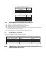
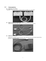
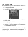
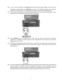
TH1775 Bias Current Source User’s Mannual -1- Chapter 1 Genernal Information ........................................................................................................................... 4 1.1 Introduction ................................................................................................................................................. 4 1.2 Main Features: ............................................................................................................................................. 4 1.3 Specifications............................................................................................................................................... 4 1.3.1 Current ............................................................................................................................................ 4 1.3.2 Display ............................................................................................................................................ 4 1.3.3 Frequency Bandwidth................................................................................................................... 5 1.3.4 Maximum Driver Capacity............................................................................................................ 5 1.3.5 Scan numbers................................................................................................................................ 5 1.3.6 Scan Delay..................................................................................................................................... 5 1.3.7 Interface.......................................................................................................................................... 5 1.3.8 Connection ..................................................................................................................................... 5 1.3.9 Warm-up time ................................................................................................................................ 5 1.3.10 Working Time............................................................................................................................... 5 1.3.11 Power ............................................................................................................................................ 5 1.3.12 Operation environment .............................................................................................................. 5 1.3.13 Dimensions .................................................................................................................................. 5 1.3.14 Weight........................................................................................................................................... 6 1.4 Basic Accuracy ............................................................................................................................................ 6 1.4.1 Accuracy Test Requirements ....................................................................................................... 6 1.4.2 Current Accuracy........................................................................................................................... 6 1.5 Additional Error for LCR Meter .................................................................................................................. 6 1.5.1 Additional error calculation........................................................................................................... 6 1.5.2 Additional Error Specification Test Conditions .......................................................................... 7 1.6 L/LCR Meters Available.............................................................................................................................. 7 1.7 Accessories .................................................................................................................................................. 8 Chapter 2 Installation and Preparation ................................................................................................................ 9 2.1 Operation Environment ............................................................................................................................... 9 2.1.1 Temperature and Humidity........................................................................................................... 9 2.1.2 Ventilation Requirments ............................................................................................................... 9 2.1.3 Line-Voltage Regulation ............................................................................................................... 9 2.1.4 Storage ........................................................................................................................................... 9 2.2 Power-Line Connection ............................................................................................................................. 10 2.2.1 Fuse Selection............................................................................................................................. 10 2.2.2 Ground the Instrument ............................................................................................................... 10 2.3 Footswitch Connection .............................................................................................................................. 10 2.4 Turn On the Power......................................................................................................................................11 2.5 Correction after Connection .......................................................................................................................11 2.6 Check the Instruments Before Use ............................................................................................................ 12 Chapter 3 Panel Description ............................................................................................................................... 14 3.1 Front Panel Description ............................................................................................................................. 14 3.2 Rear Panel Description .............................................................................................................................. 17 Chapter 4 Basic Operation .................................................................................................................................. 18 4.1 Option Menu.............................................................................................................................................. 18 -1- 4.1.1 StartTo........................................................................................................................................... 18 4.1.2 FootMode ..................................................................................................................................... 19 4.1.3 OutTuner....................................................................................................................................... 20 4.1.4 BusMode ...................................................................................................................................... 20 4.1.5 GPIB Address .............................................................................................................................. 21 4.1.6 FileNum ........................................................................................................................................ 22 4.1.7 Calibration .................................................................................................................................... 22 4.2 Single Out Mode........................................................................................................................................ 23 4.3 Setup for MultScan and Equ Scan ............................................................................................................. 25 4.3.1 Auto ............................................................................................................................................... 25 4.3.2 Step ............................................................................................................................................... 26 4.3.3 SetI ................................................................................................................................................ 26 4.3.4 Dela ............................................................................................................................................... 28 4.3.5 Retu............................................................................................................................................... 28 4.4 MultScan Mode ......................................................................................................................................... 30 4.5 Equ Scan Mode.......................................................................................................................................... 32 4.6 Messages displayed during operation ........................................................................................................ 34 4.6.1 OverLoad...................................................................................................................................... 34 4.6.2 Unbal............................................................................................................................................. 34 -2- Warranty This Tonghui instrument product is warranted against defects in material and workmanship for a period of one year from the date of shipment. During the warranty period, we will, at out option, either repair or replace products which prove to be defective. For warranty service or repair, this product must be returned to a service facility designated by Tonghui. Purchaser shall prepay shipping charges to Tonghui and Tonghui shall pay shipping charges to return the product to Buyer. However, Buyer shall pay all shipping charges, duties, and taxes for products returned to Tonghui from another country. The foregoing warranty shall not apply to defects resulting from improper or inadequate maintenance by Buyer, Buyer-supplied software or interfacing, unauthorized modification or misuse, operation outside of the environmental specifications for the product, or improper site preparation or maintenance. Tonghui Electronic Co., Ltd. No. 3, Tianshan Road, New District, Changzhou,Jiangsu, China. Tel: 86-519-85132222 Fax:86-519-85109972 www.tonghui.com.cn 3 Chapter 1 1.1 Genernal Information Introduction TH1775 is a MPU-controlled DC Bias Current Source, covering a DC bias current range from -20A to 20A. TH1775 can be used with most of Tonghui’s L meters and LCR meters. TH1775 provides a convenient and practical DC Bias Current Source for AC+DC overlap inductor measurement and magnetic material analysis. TH1775 provides three types of output modes: Single Out MultScan Equ Scan MultiScan and Equ Scan output modes can be performed either manually or automatically for different occasions. Loop function can be enabled for both MutiScan and Equ Scan modes. Newly developed theory of AC+DC overlap measurement is adopted to ensure high accuracy and high frequency measurement demands. User’s data and all test conditions are stored in non-volatile memory and do not change when power has been off or after a reset. It’s very easy and convenient for daily operation. 1.2 Main Features: Forward and reverse current can be switched. Output current can be finely adjusted in Single Out mode. Loop Scan measurement can be performed automatically or manually. A footswitch can also be used to control the bias current output. Up to 5 sets of control settings can be stored to five files. 1.3 1.3.1 Specifications Current From -20A to +20A. Three different current ranges are available (200mA, 2A and 20A). TH1775 can select the correct range automatically according to the current value user set. Up to 4 slave TH1775s can be paralleled to output a maximum bias current 100A. 1.3.2 Display 2×20 large characters LCD display. 4 1.3.3 Frequency Bandwidth From 1 kHz to 1 MHz. 1.3.4 1.3.5 Maximum Driver Capacity Output voltage: 8Vmax Maximum Tolerance of unknown DCR: Rmax = 7.5/I [Ω] (I is the setting current, unit [A]) Maximum Tolerance of unknown inductance: Lmax=100/I [mH] (I is the setting current, unit [A]) Maximum Open-circuit time Tmax = 1 [second] (Maximum current settling time.) Scan numbers From 2 to 15 points 1.3.6 Scan Delay From 0 to 99s 1.3.7 Interface TH1775 provides Slave Link interface, RS232C interface (optional) and GPIB interface (optional). 1.3.8 Connection TH1775 can be directly used with and controlled by some of Tonghui’s L meters or LCR meters. 1.3.9 Warm-up time Warm up the instrument for about 30 minutes 1.3.10 Working Time TH1775 can work continuously 1.3.11 Power Power supply: 95 to 125V AC Line frequency: 48 to 62Hz Power consumption: ≤500VA 1.3.12 Operation environment Temperature: 0 to 40℃ Humidity: ≤80%RH 1.3.13 Dimensions 430(width) ×180(height) ×460(depth) mm 5 1.3.14 Weight Approx. 15kg. 1.4 Basic Accuracy 1.4.1 Accuracy Test Requirements Within one year factory calibration Environment temperature: 25±5℃; Relative Humidity: ≤80% Power is regulated by a line-voltage regulator Warm up time: more than 30 min. 1.4.2 Current Accuracy Range Current 200mA 0.0mA to 200.0mA 1.5 Accuracy 2A 0.201A to 2.000A 20A 2.001A to 20.00A Resolution 0.1mA ±(1%+ 3digits) 0.001A 0.01A Additional Error for LCR Meter An additional measurement error should be added to the basic error of the LCR meter, when the LCR meter is used with a bias current source. The additional measurement error is induced by attenuation of test signal source, disturbance, and non-ideal coupling, and so the reading stability will be decreased. NOTE: There may be a resonance frequency point between the bias current source and the inductor under test. Around the resonance frequency point the measurement result will be different, so try best to avoid the very resonance frequency point. 1.5.1 Additional error calculation Basic additional error is ±1%, and the error will be increasing with the value of impedance under test. Use the following formula to calculate the additional error. Ze=±1%(1+kl+kf+ki)(1+Zx/2kΩ) 1) 2) 3) 4) Zx ki kl kf Unknown impedance of Zx=2πfL Bias current factor Unknown inductance factor Frequency factor Current Factor ki Current Range ki 0.0mA to 2A 0 2A to 20A 1 6 Unknown Inductance Factor kl Unknown Inductance kl 0 uH to 20uH 0.5 20uH to 2mH 0 2mH to 200mH 1 Frequency Factor kf 1.5.2 1.6 Frequency Range kf 1kHz to 10kHz 0 10kHz to 100kHz 0.5 100kHz to 300kHz 1 300kHz to 1MHz 2 Additional Error Specification Test Conditions Use the L or LCR meters manufactured by Tonghui Select slow or medium measurement speed for LCR meter. LCR’s test signal voltage level more than 0.25Vrms Use the test cable and accessories provided with the instrument and Link the instruments according to the instruction in this manual. Perform SHORT correction after linking with the Bias current source. L/LCR Meters Available TH1775 can be used with following L meters or LCR meters. Model Description Control Interface TH2773A,TH2775,TH2776 L Meter None TH2810,TH2811,TH2812 Series LCR Meter None TH2816A, TH2816B Wide Frequency LCR Meter Yes(TH2816A only ) TH2817, TH2817A Precision LCR Meter Yes (TH2817A only) TH2818, TH2819 Precision Component Analyzer Yes NOTE1: NOTE2: In case of product changes and updates, please check our newest Catalog. LCR meters based on the four-terminal pair theory can not be used with TH1775, for example the TH2828 LCR meter series. 7 1.7 Accessories TH26004E-1 Test Fixture TH26004E-1 Test Fixture used to connect the TH1775 with the L or LCR meter TH26013 DC Bias Test Clip Leads TH26013 DC Bias Test Clip Leads is used to connect the Device Under Test. TH2881-001 Footswitch TH2881-001 Footswitch can be efficiently used to start the bias current output instead of key operation from the front panel. 8 Chapter 2 2.1 2.1.1 Installation and Preparation Operation Environment Temperature and Humidity Don’t use the instrument in a dusty or vibrating location. Don’t expose the instrument under sunlight, or corrosive gas. Be sure that the operation temperature is between 0℃and 40℃ and that the relative humidity is below 80%. 2.1.2 Ventilation Requirments To void internal temperature increase under large bias current output, make sure that there is adequate clearance (more than 20 cm) around the TH1775 and adequate ventilation is ensured. Never block the ventilation windows especially on both sides and below. Rear Window Left Window TH1775 Front Panel Right Window Bottom Window 2.1.3 Line-Voltage Regulation The instrument has been carefully designed to reduce the disturbance from the AC line input. It is recommended to be used in a low noise environment. If the noise is inevitable, please use a proper power filter or a line-voltage regulator. Regulator Power Filter 2.1.4 TH1775 Storage If the instrument will not be used for a long time, please store it in the original or similar package box and keep it from direct sunlight and humidity. 9 2.2 Power-Line Connection GPIB AC LINE SLAVE LINK 10A AC 110V/60Hz 500VA Max RS-232C FOOT SWITCH 2.2.1 Fuse Selection Use 10A Slow Blow fuse for 95V to 125V line voltage. Use only fuses with the required current rating and of the specified type as replacements. To prevent electrical shock, disconnect the TH1775 power cable from the receptacle before checking or replacing the fuse. 2.2.2 Ground the Instrument In accordance with international safety standards, this instrument is equipped with a three-wire power cable. When connected to an appropriate ac power outlet, this cable grounds the instrument frame. NOTE: For protection from electrical shock, the power cable ground must not be defeated. The power plug must be plugged into an outlet that provides a protective earth ground connection. The ground terminal on the front panel can also be grounded. 2.3 Footswitch Connection Connect the foot switch when it is needed. There are two control modes for foot switch, please refer to the description late in this manual. 10 2.4 Turn On the Power Follow the following steps to turn on the both instruments, when TH26004E-1 and TH26013 is not connected: 1) Turn on the L meter or LCR meter 2) Set up the working conditions for LCR meter. 3) Turn on the TH1775 bias current source 4) Connect the TH1775 and the LCR meter with TH26004E-1 as shown in the following figure. 5) Connect TH26013 test clip leads to the TH1775 as shown in the following Figure. Some L/LCR meters will not pass the power-on self-test with a bias current source connected to their UNKNOWN terminals. Follow the following steps to turn on the instruments when TH26004E-1 and TH26013 are connected: 1) Disconnect the TH26004E-1 for one end. 2) Turn on the LCR meter and then the TH1775 3) Connect the TH26004E-1 again. 4) If you do want to turn on the instruments when they are connected, please turn on the TH1775 first, and then turn on the L/LCR meter. 5) On the contrary, if you want to turn off the instruments when they are connected, please turn off the L/LCR meter first and then turn off the TH1775. 2.5 Correction after Connection TH1775 is a Bias current source with low additional errors. Some L/LCR meters will fail in OPEN correction because of their lower noise allowance capability. At this time, please perform the OPEN correction without connecting with the TH1775. The accuracy being affected will be within the specifications if the impedance of UNKNOWN is less than 10 kΩ. For OPEN and SHORT correction operation, please refer to the user’s manual of the LCR meter. 11 Open the test terminals as shown in the following figure to perform the OPEN correction for LCR meter. Short the test terminals as shown in the following figure to perform the SHORT correction for LCR meter. 2.6 Check the Instruments Before Use After turning on the instruments, make some simple tests to ensure that the instruments are working normally. It will be reseted internally, initialized and self tested when TH1775 is turned on. At first the FWD(+), REV(-), and the slave indicators will be turned ON, the instrument and manufacturer information will be displayed for several seconds as shown in the following figure. TH775 will finish its power-on operation until the FWD(+), REV(-), and the slave indicators are turned off. The output display page will be displayed after the information display page is cleared as shown in the following figure. 12 TH1775 will be working in the Single Out output mode by factory default. (If the user has changed the configuration in the OPTION menu, then TH1775 will be working in the mode user specified, and the output current value and parameters set last time will be displayed.) Connect an amperometer to the UNKNOWN terminals as shown in the following figure. When output current is not enabled, there is no current outputted. Press [START] button to enable current output, and the setup current will be outputted. Compare the measuring current value from the amperometer and the setup current value displayed on the TH1775. Check the measuring impedance of short circuit, open circuit, short correction, open correction, and standard samples when TH1775 is connected and without current output as shown in the following figure. From the measuring impedance values above you will see if the instruments are connected and working normally. In general, short circuit impedance should be as low as possible and open circuit impedance should be as large as possible. The measuring results when bias current is disabled should be consistent with the results measured directly by a L/LCR meter. 13 Chapter 3 3.1 Panel Description Front Panel Description 10 11 1 2 3 HD HS LS TONGHUI ELECTRONICS LD TH1775 BIAS CURRENT SOURCE(0 ~ FROM LCR METER GND 20A) POWER ! WARNING: ※ TURN BIAS CURRENT OFF BEFORE DISCONNECTING DEVICE UNDER TEST FROM TEST CABLE; ※ DEVICE UNDER TEST AND TERMINALS MAY BECOME HOT DUE TO HIGH POWER DISSIPATION OF THE DUT. SLAVE FWD(+) REV(-) 7 Auto 8 9 Retu 4 5 6 mA S1 UNKNOWN COM H CUR H POT L POT LCUR S2 RESET 1 S3 0 S4 9 1) 2) 3) 4) 8 12 7 6 Opt START 5 Step 2 3 F/R . Mode +/SetI Dela Esc 4 Brand and Model LCD Display 2×20 character LCD display, the working conditions and setup parameters are displayed. Power Switch In the “1” position all operating voltages are applied to the instrument. In the “0” position NO operating voltages are applied to the instrument. Keyboard [Mode] key Current output mode selection. There are three types of current output modes: Single point current output mode Single Out, Multi-point current output mode MultScan and Equal interval multi-point current output mode Equ Scan. Press the [Mode] key to select one of the three current output modes in turn: Single Out → MultScan → Equ Scan. [SetI] key Use the [SetI] key to set the output current value displayed on the LCD screen. [Auto] key Press [Auto] key to set the Automatic scan mode (AutoScan = 1) or Manual scan mode (AutoScan = 0) when MultScan or Equ Scan output mode is used. [Retu] key Press [Retu] key to enable (Return = 1) or disable (Return = 0) the loop current measurement when MultScan or Equ Scan output mode is used. [Step] key Press [Step] key to set the Scan Numbers from 2 to 15 when MultScan or PartScan output mode is used. 14 [Dela] key Press [Dela] key to set up the “Scan Delay” time from 0 to 99 sec. When Auto scan is ON, the next current point will be outputted automatically after the “Scan Delay” time is expired. When Auto scan is OFF, the next current will not be outputted until the [START] button is pressed or the footswitch is stepped after the “Scan Delay” time is expired. NOTE: The setup parameters for [SetI], [Auto], [Retu], [Step] and [Dela] can be stored automatically and will not be lost when power has been off or after a reset. [Option] key Press y key to save the parameters modified in the Option Menu to the current FileNum file. Press } key to cancel the parameters modified in the Option Menu. [F/R] key [F/R] is the current forward and reverse switching key. This key is valid only when Single Out mode is selected and the bias current output is started. NOTE: All above key operations except [F/M] key is available only when the bias current output is not started. y key Press y key to confirm the modification with the parameters. } Press } key to cancel or exit the parameter setup. [←] key Press [←] key to delete one last character of the input value. This key can only be used when output current, Scan Numbers or Scan Delay time is to be inputted. Numeric Keys: ,,,,,,,,, The numeric keys are used to input a data. For example, when bias current, Scan Numbers or Scan Delay time is to be inputted. Cursor Keys: o,p,q,r The cursor keys are only available when corresponding symbols (_, `, a, b) are displayed on the LCD screen. The cursor keys can be used to select a scan current point which you want to modify. The cursor keys can also be used to adjust the Single Out current value finely. Finally the cursor keys can be used in Option menu to switch between option menus and to set the parameters for each menu. 15 5) [START] button Start a current output or change to the next scan output current point. 6) Current output indicators FWD(+) indicates that a forward current is being outputted. REV(-) indicates that a reverse current is being outputted 7) [RESET] button Press [RESET] button to interrupt a bias current output immediately. 8) UNKNOWN terminals UNKNOWN terminals are used to connect a device under test. Hcur:High terminal of current drive Hpot:High terminal of potential sense Lpot:Low terminal of potential sense Lcur:Low terminal of current drive Hcur and Hpot terminals are connected to a red clip. Lcur and Lpot terminals are connected to another black clip. 9) COMMON terminal This is the COMMON terminal which is tied to the instrument’s chassis and which can be used for measurements that require guarding. 10) GND This is the GND terminal which is tied to the instrument’s chassis and which can be connected to a protective earth ground to protect from electrical shock. 11) LCR terminals Connect these LCR terminals to the Unknown terminals of a LCR meter using the TH26004E-1 accessory. Make sure that every terminal is connected to its corresponding terminal. HD of TH1775 is connected to Hcur (HD) of a LCR meter. HS of TH1775 is connected to Hpot (HS) of a LCR meter. LS of TH1775 is connected to Lpot (LS) of a LCR meter LD of TH1775 is connected to Lcur (LD) of a LCR meter 12) Slave Indication Indicate that a slave instrument is connected successfully. 16 3.2 Rear Panel Description GPIB AC LINE SLAVE LINK AC 110V/60Hz 500VA Max 10A RS-232C FOOT SWITCH 4 5 8 6 1 7 2 3 1) GPIB interface (optional) This optional interface provides a way to communicate with a computer and other instruments which are also equipped with GPIB interfaces. 2) RS232C Interface (optional) The RS232C interface is also an optional interface which can be used to communicate with a computer and with some of our L/LCR meters which can be programmed to control a bias current source. 3) Footswitch A foot switch can be used to trigger the TH1775. Several control modes of the footswitch can be 4) selected from the Option menu “FootMode”. Fuse Use a 10A slow blow fuse for this instrument. Press the fuse holder and turn anti-clockwise at the same time to loose the fuse holder. Press the fuse holder and turn clockwise at the same time until the fuse holder is locked. Warning! Disconnect the power cable before replacing the fuse! 5) Line Receptacle Use the standard three-wire power cable provided with the instrument. 6) Cooling Fan TH1775 uses two cooling fans. Make sure that sufficient space must be kept around the TH1775 to avoid obstructing the air flow of the cooling fans. 7) Slave Link Up to 4 slave bias current sources can be paralleled to provide a maximum 100 A bias current. 8) Name Plate Provide the information of Serial number and name of manufacture. 17 Chapter 4 Basic Operation The foregoing chapters have introduced the basic of using this instrument. This chapter will tell you how to set the functions and parameters through the keyboard to meet different measurement requirements. When all functions and parameters have been finished, operation will become very simple. Just press the [START] or [RESET] buttons to perform the measurement, sometimes only a footswitch is needed. NOTE: Functions and parameters can only be set when bias current is OFF. 4.1 Option Menu Not all items in the Option menu are necessary for TH1775, but the setups will make your measurement more convenient and efficient. For example you can select the footswitch control mode as you like, and set the proper Scan Delay time you want. Press [OPt] key to enter the display page of <Set Options> in the Option menu as shown in the following figure. “Set Options” in the first line indicates current display page. The item displayed on the left of “=” is the current menu item to be modified. The value or option of current item is displayed on the right of “=”. The arrow marks displayed on the bottom right screen remind you to select a menu item using the r or q key and to change the value of the current menu item using the p or 4.1.1 o key. StartTo Perform the following steps to set the default output current mode when TH1775 is turned on. 1) 2) Press [Opt] key from the output display page to enter the <Set Option> display page as shown in the following figure. Press p or 3) o key to set “StartTo” to Singl, Mult or Equal. StartTo = Singl Set the Single Out mode as the default current output mode. StartTo = Mult Set the MultScan mode as the default current output mode. StartTo = Equal Set the Equ Scan mode as the default current output mode. Press y key to confirm and save the change of StartTo and return back to the current output 18 page. When TH1775 is turned on, the specified “StartTo” mode you have just set will be displayed. 4) Press } key to cancel the change of StartTo and return back to the current output page. 5) Whatever default current mode you have selected, you still can switch the output mode by pressing the [Mode] key directly. However the default mode of StartTo will not be changed by pressing the [Mode] key. 4.1.2 FootMode Perform the following procedures to set up the footswitch control mode. 1) Press [Opt] key from the output display page to enter the <Set Option> display page. 2) Press q key to select the “FootMode” menu item. The current control mode will be displayed as shown in the following figure. 3) Press p or o key to select Trig, Hold or OFF control mode. FootMode = OFF Footswitch is disabled. FootMode = Trig Trig Operation: Step on the footswitch and then loose your foot to accomplish a trigger action. For Single Out mode, the first footswitch trigger action (same as [START] button pressing) will start the bias current output and the second footswitch trigger action (same as [RESET] button pressing) will interrupt the bias current output immediately. For MultScan or Equ Scan mode and AutoScan is set to Auto mode, the footswitch can only be used to start the current output. If you want to interrupt the current output, you have to press the [RESET] button on the front panel. For MultScan or Equ Scan mode and AutoScan is set to Manual mode, the first footswitch trigger action will start the bias current output and each following footswitch trigger action will change the output current to the next scan current point until all setup current points have been finished. FootMode = Hold Hold mode is available only when Single Out mode is used. Step on the footswitch and hold on to enable bias current output, and the bias current will be interrupted as soon as you loose the footswitch. Footswitch operation for MultScan or Equ Scan is the same as when Footmode is set to Trig mode. 19 4) Press y key to confirm and save the change of FootMode and return back to the current output page. 5) Press } key to cancel the change of FootMode and return back to the current output page. 4.1.3 OutTuner This function is only available when Single Out mode is used, which can be used to finely adjust the current output value using the cursor keys. It’s very useful for product experiment, product research and development, characteristic analysis. Perform the following procedures to turn on/off the OutTuner function. 1) Press [Opt] key from the output display page to enter the <Set Option> display page. 2) Press r or q key to switch to the “OutTuner” menu item. The current setup will be displayed as shown in the following figure. 3) Press p or 4) o key to turn on or off the OutTuner function. OutTuner = OFF Turn off the OutTuner Function. OutTuner = ON Turn on the OutTuner function. Press y key to confirm and save the change of OutTuner and return back to the current output page. 5) 4.1.4 Press } key to cancel the change of OutTuner and return back to the current output page. BusMode Perform the following procedures to set up the BusMode. 1) Press [Opt] key from the output display page to enter the <Set Option> display page. 2) Press r or q key to switch to the “BusMode” menu item. The current setup will be displayed as shown in the following figure. 3) Press p or o key to set the BusMode to LCR, GPIB, RS232 or OFF mode. 20 Note: When BusMode is set to LCR mode, the <Set Options> display page will be displayed instead of output display page after Power is on. You can set the BusMode to other modes from the <Set Options> page. When BusMode is selected, the keyboard will be forbidden on the output display page. If you want to change the BusMode, just turn off the instrument and turn on the instrument again, and then change the BusMode from the <Set Options> display page. BusMode=GPIB When BusMode is set to GPIB, TH1775 will be controlled through the GPIB interface which is an option. Another computer fixed with a GPIB interface card is required to control the TH1775. Operation manual for GPIB interface will be provided together with the GPIB option. BusMode=RS232 When BusMode is set to RS232, TH1775 will be connected and controlled by a computer. BusMode=OFF When BusMode is set to OFF, TH1775 can only be operated from the front panel. 4) BusMode=LCR When BusMode is set to LCR, TH1775 is connected by a LCR meter through the RS232 interface and the bias current output can be set and controlled through the LCR meter. Press y key to confirm and save the change of BusMode and return back to the current output page. 5) 4.1.5 Press } key to cancel the change of BusMode and return back to the current output page. GPIB Address Set the GPIB address for this TH1775 from 1 to 31. Perform the following procedures to set the GPIB Address. 1) Press [Opt] key from the output display page to enter the <Set Option> display page. 2) Press r or q key to switch to the “Address” menu item. The current setup will be displayed as shown in the following figure. 3) Press p or 4) Press o key to set the GPIB Address from 1 to 31 for TH1775. y key to confirm and save the GPIB Address and return back to the current output page. 5) Press } key to cancel the change of GPIB Adddress and return back to the current output 21 page. 4.1.6 FileNum Select the current File number for storing and reloading the parameters and configurations. Up to 5 sets of configurations can be saved in FileNum 1 to 5. User can save the different sets of scan point values to different file for later use. Following parameters and states are stored in the file: 1) The default StartTo mode when TH1775 is powered on. 2) Parameters set in the “Option menu” 3) Output current value “Io” for Single Out mode. 4) Current point values for MultScan mode 5) Current value of Is and Ie for Equ Scan mode. 6) Scan Delay time (0 to 99s) 7) AutoScan mode (Manual/Auto) 8) Return mode (Not/Return) 9) Scan Numbers (2 to 15) Note: All parameters are saved automatically in the current FileNum when they are modified. Perform the following procedures to select a FileNum and reload the configurations. 1) Press [Opt] key from the output display page to enter the <Set Option> display page. 2) Press r or q key to switch to the “FileNum” menu item. The current FileNum will be displayed as shown in the following figure. 3) Press p or 4) Press o key to select a FileNum to reload from 1 to 5. y key to confirm the FileNum selection and reload the configurations. TH1775 will return back to the current output page. 5) Press } key to cancel the FileNum selection and the configurations will not be loaded. TH1775 will return back to the current output page 4.1.7 Calibration Calibration function is not available for common users, which can only be used by qualified personals in the calibration laboratory of Tonghui. 22 4.2 Single Out Mode Single Out mode is the most commonly used output mode. A single current is outputted after the TH1775 is started. If you want more than one current, please select the MultScan or Equ Scan mode. Perform the following steps to measure a DUT using Single Out mode: 1) Use the [Mode] key to select the Single Out mode as shown in the following figure. “Stop” at the bottom right means that the bias current has not been started. Io is the present output current value. 2) 3) Press [SetI] key to set the output current value. The <Input Data> display page will be displayed as shown in the following figure. Use the entry keys (,,,,,,,,,,,,[mA]) to set up the current value from -100A to 100A. 4) Press y key to confirm the Io value and return back to the current output page. If a current value out of the maximum value is inputted, “Data Out” error message will be displayed for a while. TH1775 will return back to the <Input Data> page in step 2. Try to enter a correct current value again. 5) 6) 7) Press } key to cancel the Io value and return back to the current output page. Connect the device under test to the UNKNOWN terminals of TH1775. Press [START] button to start the bias current output. Trig the footswitch once to start the bias current output. (FootMode= Trig) Step on the footswitch and hold on to enable the bias current output. (FootMode = Hold) If the Io value is more than 20A, and the slave instrument is not connected, “Slave1 NotReady” will be displayed as shown in the following figure. 23 A forward current is outputted when LED FWD(+) is ON. Message “Run” will be displayed at the bottom right corner of the LCD indicating that the bias current is ON as shown in the following figure. 8) Press [F/R] key to change the current direction between FWD(+) and REV(-). When a reverse current is outputted, LED REV(-) will be lighted as shown in the following figure. 9) The indications of arrow keys will be displayed on the right of the current output value, if the OutTuner function is on. Use the r or q key to select one of the last two digits to be changed, and a cursor will be blinking under the digit to be changed. Once a digit has been selected, press p or o key to increase or decrease the current output value. 10) Read the measuring results from the LCR meter. 11) Press [RESET] button to interrupt the bias current output. Trig the footswitch once again to interrupt the bias current output. (FootMode= Trig) Loose the footswitch to interrupt the bias current output. (FootMode = Hold) 12) Disconnect the device under test. 13) Repeat step 6 to 12 to measure other devices. Warning Device under test, terminals and adjacent area may become hot due to high power dissipation of the DUT. Be careful when exchanging devices 24 Warning! Turn off the BIAS current before disconnecting the device under test from the test fixture! 4.3 Setup for MultScan and Equ Scan Working parameters and modes (such as AutoScan, Return, Scan Numbers and Scan Delay) have to be set before using the MultScan or Equ Scan mode. 4.3.1 Auto There are two scan operation modes for MultScan and Equ Scan: AutoScan = 0 (Manual) [START] → I1 → [START] → I2 → …→ [START] → In → [START] → Scan Over AutoScan = 1 (Auto) [START] → I1 → Delay → I2 → Delay → … → In →Delay → Scan Over Perform following steps to set AutoScan mode: 1) Press [Mode] key to select the MultScan or Equ Scan mode. 2) Press [Auto] key to to enter the <SetAutoScan> display page as shown in the following figure. 3) Press to select the Auto mode or press to select the Manual mode. 4) Press y key to confirm the AutoScan mode and return back to the current output page. 5) Press } key to cancel the AutoScan mode and return back to the current output page. 6) If Auto mode is selected, “A” will be displayed on the top right corner of the LCD as shown in the following figure. 25 4.3.2 Step Scan Numbers is the maximum current points you want to output. Perform following steps to set Scan Numbers: 1) Press [Mode] key to select the MultScan or Equ Scan mode. 2) Press [Step] key to to enter the <Input Date> display page as shown in the following figure. 3) 4) Use the numeric keys to input the Scan Numbers from 2 to 15. Press [←] (Backspace) key to delete the digit before the cursor. Press y key to confirm the input and return back to the former display page. If the input number is out of the range from 2 to 15, TH1775 will clear the wrong scan number and require you to input again. 5) Press } key to cancel the input and return back to the former display page. 4.3.3 SetI Set the output current values for Single Out, MultScan and Equ Scan modes. Perform the following steps to set the IO current for Single Out mode. 1) Press [Mode] key to select the Single Out mode. 2) Press [SetI] key to enter the IO <Input Data> display page as shown in the following figure. 3) Use the entry keys (, , , , , , , , , , , , [mA]) to set up the current value from -100A to 100A. 4) Press y key to confirm the IO value and return back to the current output page. If a current value out of the maximum value is inputted, “Data Out” error message will be displayed. TH1775 will return back to the <Input Data> page in step 2. Try to enter the right current value again. 5) Press } key to cancel the IO value and return back to the current output page. 26 Perform the following steps to input the current values from I1 to In for MultScan mode. 1) Press [Mode] key to select the MultScan mode. 2) Set the Scan Number for MultScan mode first. 3) Use p or o key to select a current point from I1 to In. 4) Press [SetI] key to enter the <Input Data> display page as shown in the following figure. 5) Use the entry keys (, , , , , , , , , , , , [mA]) to set up the current value from -100A to 100A. 6) Press y key to confirm the input value and return back to the current output page. If a current value out of the maximum value is inputted, “Data Out” error message will be displayed. TH1775 will return back to the <Input Data> page in step 5. Try to enter the right current value again. 7) Press } key to cancel the input value and return back to the current output page. 8) Use p or o key to select another current point from I1 to In. 9) Repeat step 3 to step 8 to input other current points. Perform the following steps to set the Is and Ie currents for EQU Scan mode. 1) Press [Mode] key to select the Equ Scan mode. 2) Set the Scan Number for Equ Scan mode first. 3) Use p or o key to select the start current Is. 4) Press [SetI] key to enter the <Input Data> display page as shown in the following figure. 27 5) Use the entry keys (, , , , , , , , , , , , [mA]) to set up the current value from -100A to 100A. 6) Press y key to confirm the Is value and return back to the current output page. If a current value out of the maximum value is inputted, “Data Out” error message will be displayed. TH1775 will return back to the <Input Data> page in step 5. Try to enter the right current value again. 7) Press } key to cancel the input value and return back to the current output page. 8) Use p or o key to select the end current Ie. 9) Repeat step 4 to step 7 to input the end current Ie. 4.3.4 Dela Set the Scan Delay for MultScan or Equ Scan mode, when AutoScan is set to Auto mode. Perform the following steps to set the Scan Delay time: 1) Press [Mode] key to select the MultScan or Equ Scan mode. 2) 3) Press [Dela] key to enter the <Input Data> display page as shown in the following figure. Use the numeric keys (, , , , , , , , , ) to input the delay time from 0 to 99s. 4) Press y key to confirm the input value and return back to the current output page. 5) Press } key to cancel the input value and return back to the current output page. 4.3.5 Retu Loop function can be enabled to analyze the characteristics of magnetic materials. When loop function is on (Return = 1), the multi-current will be outputted like this: Start → I1 → I2 → … → In-1 → In → In-1 → … → I2 → I1 → End Perform the following steps to turn on/off the loop function: 1) Press [Mode] key to select the MultScan or Equ Scan mode. 28 2) Press [Retu] key to enter the <Set Return> display page as shown in the following figure. 3) Press to select the Return mode or press to select the Not mode. 4) Press y key to confirm the setup and return back to the current output page. 5) Press } key to cancel the setup and return back to the current output page. 6) If Return mode is selected, “R” will be displayed on the top right of the LCD as shown in the following figure. 29 4.4 MultScan Mode TH1775’s MultScan Mode permits user to measure the device over different DC bias current points. It’s very useful if you want to analyze the characteristics of some kind of magnetic materials. From 2 to 15 different bias currents can be set. TH1775 will output the bias currents in the order I1, I2, … , In with a delay time from 0 to 99 seconds between different current points (Auto mode). For some special measurement needs, loop current function can be used. Perform following steps to measure a device in MultScan and Auto mode: 1) Press [Mode] key to select the MultScan mode. 2) Press [Auto] key to select the Auto scan mode, referring to paragraph 4.3.1. 3) Press [Step] key to set the Scan Numbers, referring to paragraph 4.3.2. 4) Press [SetI] key to set the current value for each point, referring to paragraph 4.3.3. 5) Press [Dela] key to set the Scan Delay time, referring to paragraph 4.3.4. 6) Press [Retu] key to set the loop function, referring to paragraph 4.3.5. 7) Set the footswitch mode to Trig mode. 8) The setups are listed below, and the following display page will be displayed. Auto operation mode Scan Numbers = 6 Scan Delay = 5 sec Loop function enabled FootMode = Trig 9) Connect the device to the UNKNOWN terminals. 10) Press [START] or trigger the footswitch to start the bias current output. The current points will be outputted automatically in the following order: [START] → I1 → Delay → I2 → Delay → … → I6 →Delay → I5 → Delay→ … → I2 → Delay→ I1 → Delay → Over 11) [START] button or footswitch can both be used to skip the delay time and switch to the next point directly. 12) Read the measurement results from the LCR meter. 13) Press [RESET] button to end the measurement at any time. 14) Disconnect the device under test. 15) Repeat step 9 to step 14 to test other devices. Perform following steps to measure a device in MultScan and Manual mode: 1) Press [Mode ] key to select the MultScan mode. 2) Press [Auto] key to select the Manual scan mode, referring to paragraph 4.3.1. 3) Press [Step] key to set the Scan Numbers, referring to paragraph 4.3.2. 4) Press [SetI] key to set the current value for each point, referring to paragraph 4.3.3. 5) Press [Retu] key to set the loop function, referring to paragraph 4.3.5. 30 6) 7) Set the footswitch mode to Trig mode. The setups are listed below, and the following display page will be displayed. Manual operation mode Scan Numbers = 6 Loop function disabled FootMode = Trig 8) Connect the device to the UNKNOWN terminals. 9) Press [START] or trigger the footswitch to start the bias current output. 10) Read the measurement result from the LCR meter. 11) Press [START] or trigger the footswitch to the next current point. 12) Repeat step 10 and 11, until all current points are finished. 13) Press [RESET] button to end the measurement at any time. 14) Disconnect the device under test. 15) Repeat step 8 to step 14 to test other devices. 31 4.5 Equ Scan Mode For Equ Scan mode, you don’t have to input the values for all current points. Only IS and Ie are required be inputted. The TH1775 will automatically calculate the value for each point according to equal current interval rule. For example: if Scan Numbers is N, start current is IS, and end current is Ie. We can calculate the current values for each point: I1=Is; I2=Is + (Ie-Is)/(N-1) ... In=Is + (n-1) (Ie-Is)/(N-1) ... IN= Is + (N-1) (Ie-Is)/(N-1) = Ie From 2 to 15 different bias currents can be set. TH1775 will output the bias currents in the order I1 (Is), I2, …, In (Ie ) with a delay time from 0 to 99 seconds between different current points (Auto mode). For some special measurement need, loop current function can be used. Perform following steps to measure a device in Equ Scan and Auto mode: 1) Press [Mode] key to select the Equ Scan mode. 2) Press [Auto] key to select the Auto scan mode, referring to paragraph 4.3.1. 3) Press [Step] key to set the Scan Numbers, referring to paragraph 4.3.2. 4) Press [SetI] key to set the current value for Is and Ie, referring to paragraph 4.3.3. 5) Press [Dela] key to set the Scan Delay time, referring to paragraph 4.3.4. 6) Press [Retu] key to set the loop function, referring to paragraph 4.3.5. 7) Set the footswitch mode to Trig mode. 8) The setups are listed below, and the following display page will be displayed. Auto operation mode Scan Numbers = 6 Scan Delay = 5 sec Loop function enabled FootMode = Trig 9) Connect the device to the UNKNOWN terminals. 10) Press [START] or trigger the footswitch to start the bias current output. The current points will be outputted automatically in the following order: [START] → I1 → Delay → I2 → Delay → … → I6 →Delay → I5 → Delay→ … → I2 → Delay→ I1 → Delay → Over 11) [START] button or footswitch can both be used to skip the delay time and switch to the next point directly. 12) Read the measurement results from the LCR meter. 32 13) Press [RESET] button to end the measurement at any time. 14) Disconnect the device under test. 15) Repeat step 9 to step 14 to test other devices. Perform following steps to measure a device in Equ Scan and Manual mode: 1) Press [Mode ] key to select the Equ Scan mode. 2) Press [Auto] key to select the Manual scan mode, referring to paragraph 4.3.1. 3) Press [Step] key to set the Scan Numbers, referring to paragraph 4.3.2. 4) Press [SetI] key to set the current value for Is and Ie, referring to paragraph 4.3.3. 5) Press [Retu] key to set the loop function, referring to paragraph 4.3.5. 6) Set the footswitch mode to Trig mode. 7) The setups are listed below, and the following display page will be displayed. Manual operation mode Scan Numbers = 6 Loop function disabled FootMode = Trig 8) Connect the device to the UNKNOWN terminals. 9) Press [START] or trigger the footswitch to start the bias current output. 10) Read the measurement result from the LCR meter. 11) Press [START] or trigger the footswitch to the next current point. 12) Repeat step 10 and 11, until all current points are finished. 13) Press [RESET] button to end the measurement at any time. 14) Disconnect the device under test. 15) Repeat step 8 to step 14 to test other devices. 33 4.6 Messages displayed during operation Two kinds of error messages may be displayed during operation. 4.6.1 OverLoad If TH1775 and the slave current sources fail to provide the preset bias current value within 1 second, TH1775 will no longer attempt to output the bias current, and Overload message will be displayed as shown in the following figure. The possible reasons for overload: The UNKNOWN terminals are open circuit, when TH1775 is started to output a bias current. The resistance of DUT is too large to be tested. The voltage (V=IR) exceeds the maximum output voltage of TH1775. The output bias current does not reach the required current value within 1 second, when a large inductance is tested under a large bias current. TH1775 may be broken down and needs to be repaired. If the overload error message is disappeared after the UNKNOWN terminals are shorted directly, which means TH1775 is working normally. The reason for overload must be among the first three reasons listed above. The current device under test can not be measured under this bias current value. Try to measure it under a lower bias current. 4.6.2 Unbal TH1775 adopts a special balancing technology to meet the need of 4-terminal test theory of a L/LCR meter. Once error message “Master Unbal” is displayed, this means that TH1775 fails to accomplish overlap current measurement and bias current output will be disabled as shown in the following figure. Press [RESET] key to clear the error message first. Check the connection with the LCR meter and short the UNKNOWN terminals directly. Try to start the bias current again. If the “Master Unbal” error message is displayed again, there may be something wrong inside the TH1775. Please connect our company or service center for help. 34