1
QUICK GUIDE
PUMP CONTROL
Frequency inverter for pump control applications
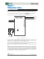
SG_PUMP_CONTROL_AQUA_EN_1.1.1
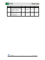
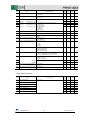
Version
1.0.0
1.1.0
1.1.1
Details
Draft version
First revision
Recommended setting changed
Wiring drawings changed
according to recommended
setting
Corrected Table 2.1
Corrected pump number in first
paragraph of page 26
Corrected default setting of J118
and J119 in table 3.1
Date
14/03/12
Written
J. Alonso
15/10/12
30/10/12
2
Checked
Approved
J.M. Ibáñez/
J. Alonso
H. Loder
J.Català
J.M. Ibáñez
H. Loder
J. Català
Pump Control Quick Guide
Thank you for purchasing
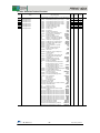
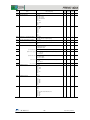
This guide is structured as follows:
,
Fuji Electric’s inverter for pump and compressor applications.
CHAPTER 0: Introduction to pressure control systems
9 types of pump control
5
CHAPTER 1: Single pump control
Electrical diagram
Sleep Function
Wake-up Function
Common parameters for pump control
Common parameters description
6
7
7
9
10
CHAPTER 2: Mono-regulated pump control with 1 regulated pump + 1 to 8 auxiliary pumps
Mono-regulated pump (mono-joker) control with 1 regulated pump + 1 auxiliary pump electrical diagram
Mono-regulated pump (mono-joker) with 1 regulated pump + 2/3 auxiliary pumps diagram using external relays
Mono-regulated pump (mono-joker) with 1 regulated pump + 2/3 auxiliary pumps diagram using OPC-G1-RY
Mono-regulated pump (mono-joker) with 1 regulated pump + 4/5 auxiliary pumps diagram using external relays
Mono-regulated pump (mono-joker) with 1 regulated pump + 4/5 auxiliary pumps diagram using OPC-G1-RY2
Mono-regulated pump (mono-joker) control with 1 regulated pump + 8 auxiliary pumps electrical diagram
Connecting auxiliary pumps
Disconnecting auxiliary pumps
Common Parameters for pump control
Specific parameters
Specific parameters description
12
13
14
15
16
17
19
20
21
22
23
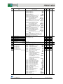
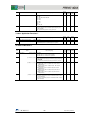
CHAPTER 3: Mono-regulated pump control with 1 regulated pump + 8 auxiliary pumps + 1 additional pump
Electrical diagram
Common parameters for pump control
Specific Parameters
Specific parameters description
25
27
28
29
CHAPTER 4: Multi-regulated pump (multi-joker) control with 2/4 regulated pumps
Multi-regulated pump (Multi-joker) control with 2 regulated pumps electrical diagram
Multi-regulated pump (Multi-joker) control with 3/4 regulated pumps electrical diagram
Connecting a regulated pump to commercial power supply
Disconnecting a regulated pump from commercial power supply
Common parameters for pump control
Specific parameters
Specific parameters description
Specific parameters description having optional card relay installed (OPC-G1-RY2)
31
34
35
36
37
38
39
39
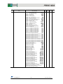
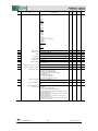
CHAPTER 5: Multi-regulated pump (Multi-joker) control with 4 regulated pumps + 1 additional pump
Electrical diagram
Common parameters for pump control
Specific Parameters
Specific parameters description
40
42
43
44
Dry Pump function
Overpressure alarm
PID Display units set-up
Start-up and switching motors sequence
Contactor delay time
Motor stop mode when RUN (FWD or REV) signal is switched off
Multiple PID set points selection
Dead Band
Dew condensation prevention function
PID Integral component hold
Enable / disable pumps by means of external selectors
46
47
48
48
49
49
49
49
50
50
52
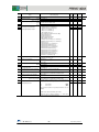
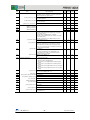
CHAPTER 6: Additional Functions
53
72
73
74
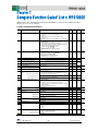
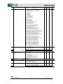
CHAPTER 7: Function codes list. Digital and analog I/O functions
CHAPTER 8: Names and functions of keypad components
CHAPTER 9: Optional relay Cards (OPC-G1-RY and OPC-G1-RY2)
CONCTACT INFORMATION
3
Pump Control Quick Guide
The target of a pressure control system is to provide a variable flow with a constant pressure for the water
system of an apartment building, machine refrigeration systems, mixing liquids in chemical industry, etc.
A very typical example is to provide the water supply for a residential building. In this case, the flow (water
consumption) is greater in the morning than during the night (when it is almost zero). The pressure control
system must be able to provide, at the same pressure, both types of consumption (daytimehigher flow,
during the night almost no flow); in addition, the system has to adapt to the demand variations that occur
normally in this kind of application, for example, when people turn on and off many taps at the same time.
The
inverter has been designed to fulfil all the requirements of the different pump control
systems. Some of its more important functions are:
•
•
•
•
•
•
•
•
•
•
•
•
•
•
•
•
•
•
•
•
•
•
•
•
Stop function due to low water flow (Sleep Function)
Start-up function because of water demand (Wake-up Function)
Operation limits (current, voltage and frequency) to protect the motor and the pump
Control of multiple pumps on 1 regulated pump + auxiliary pumps topology (Mono-regulated
pump Control)
Control of multiple pumps on multi regulated pumps topology (Multi-regulated pump Control)
Possibility to add an additional pump (AUX_L Function) to both topologies
Many functions to avoid overpressure and water losses (Warnings, alarms, etc.)
Possibility of precise adjustment of the levels for start-up and stop of the auxiliary pumps to fine
tune the system behaviour
Possibility of the precise adjustment of the levels to start-up and stop of the PID control, during
the connection/disconnection of the auxiliary pumps, to fine tune the system behaviour
Independent ramps for the start-up and the stop of the regulated pump, separate from the ramps
for the connection/disconnection of auxiliary pumps
Selection of the sequence for the pumps start-up and stop
Sequenced switching rotation of the pumps (by timer or intelligent control)
Possibility of sharing the working time between the pumps
Information about the working time of each pump
Pressure sensor disconnection detection
Selecting different warnings (low-pressure, overpressure, etc.)
Protective function to protect pump from the absence of water (Dry well function)
“By-pass” sequence integrated
Control of the delay time between connection and disconnection of the contactors
Display units and sensor range adjustments
Selectable ‘Pump Stop’ Strategy
Multiple frequency command selection (by means of digital inputs)
Dew condensation prevention Function
Energy Saving Functions
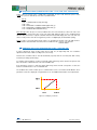
Regulation by means of PID control:
A PID control is a regulation system involving the set value (SV - desired pressure) and a process value
(PV - Feedback, measure of real pressure or flow from a transducer). From these two values the difference,
or error, is calculated, subtracting one from the other. The PID control then adjusts its output demand (MV
- pump’s speed) in order to minimize the error:
-If the error is positive (desired pressure greater than real pressure) speed should increase
-If the error is negative (desired pressure lower than the real pressure) speed should decrease
-If the error is zero (desired pressure equal to real pressure) speed should stay at the same level
Parameters (gains) to adjust: Proportional, Integral and Derivative components (though Derivative
component is not normally used in this application) help to select how quickly the system will respond to
pressure and consumption changes. Normally, a quick (dynamic) response is desired, but pressure peaks
and oscillations must be avoided.
4
Pump Control Quick Guide
QUICK GUIDE
PUMP CONTROL
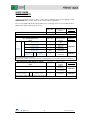
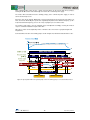
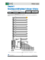
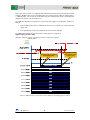
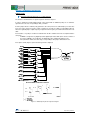
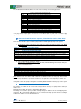
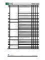
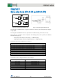
frequency inverter is able to control single or multiple pumps in mono-regulated or multiregulated configuration. Several control schemes may be built as shown below:
The necessary digital outputs will vary depending on the control type has been chosen (OPC-G1-RY or
OPC-G1-RY2 optional cards may be necessary).
Necessary
digital outputs
Single pump control
0
Do we need the
optional relay card
installed?
NO
Explained in…
CHAPTER 1
Single pump control consists of 1 pump exclusively controlled by the frequency inverter
MONO-REGULATED PUMP CONTROL (FIXED)
Necessary
Do we need the
up to 10 pumps (Mono-joker)
digital outputs
optional relay card
Explained in …
J401=1
installed?
1 auxiliary pump
1
NO
(On-Off control)
2/3 auxiliary pumps
Optional
2/3
(OPC-G1-RY)
(On-Off control)
CHAPTER 2
1
4/5 auxiliary pumps
Optional
4/5
(OPC-G1-RY2)
regulated
+
(On-Off control)
Pump
6/7/8 auxiliary pumps
YES
6/7/8
(OPC-G1-RY2)
(On-Off control)
8 auxiliary
1 additional
YES
CHAPTER 3
pumps
+
pump
9
(OPC-G1-RY2)
(On-Off control)
(On-Off control)
Mono-regulated pump control consists of 1 pump exclusively controlled by the frequency inverter and multiple auxiliary
pumps working in On-Off control mode.
Additional pump is added / removed depending on the regulated pump speed and if auxiliary pumps are all enabled or not.
MULTI-REGULATED PUMP CONTROL (FLOATING)
up to 4 pumps (Multi-joker)
J401=2
Necessary
digital outputs
2 regulated pumps
4
3/4 regulated pumps
6/8
YES
(OPC-G1-RY2)
9
YES
(OPC-G1-RY2)
4 regulated pumps
+
1 additional pump
(On-Off control)
Do we need the
optional relay card
installed?
Explained in …
Optional
(OPC-G1-RY)
CHAPTER 4
CHAPTER 5
Pumps working on Multi-regulated mode are all inverter driven.
Additional pump is added / removed depending on the regulated pump speed and if others are also enabled or not.
5
Pump Control Quick Guide
Necessary digital outputs
0
Single pump control
Do we need the optional relay card installed?
NO
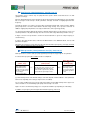
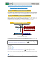
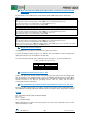
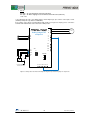
When a regulated pump is being controlled, it’s necessary to consider certain parameters in order to allow
the inverter to control the pump’s start-up and stop, controlling speed to maintain the desired pressure, etc.
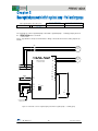
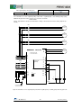
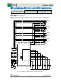
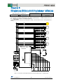
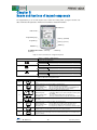
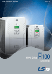
The schematic to implement control by only 1 pump by means of
inverter, is as follows:
Please note the pressure transducer is connected to the inverter’s analog input C1 (4-20 mA)
U
V
W
SINGLE PUMP CONTROL
L1
L2
L3
REGULATED
PUMP
Y1
Y2
Y3
Y4
Y5A
Y5C
30A
30B
30C
C1
C1
SW5
PLC
CMY
CM
-
+
11
P
E
Pressure transducer
4-20 mA (Vcc 24V)
Figure 1.1: control schematic for 1 pump only
By means of the TP-A1 keypad, a digital input or an analog set point, the desired pressure can be selected.
Once this pressure is set, inverter will modify pump’s speed between a minimum (J119 = F16 (Hz)) and a
maximum (J118=F15=F03 (Hz)) frequencies, in order to stabilize the pressure.
To work in this way, the integrated PID Control 1 must be enabled (J101) and adjusted properly. Then, the
inverter’s response should be the required action to control the application.
PID’s response can be modified by means of parameters J110 and J111 (Proportional gain and Integral
time).
When the “RUN” signal is switched on (either FWD or REV), the inverter will increase the output frequency
(always after the period time defined in J454 (s)). In order to control this rising output, some parameters
are available: F23 (Hz) controls the starting frequency, F16 the frequency limiter (low) and the ramp from
one to the other (F07) (s). PID Control 1 is enabled since RUN command is given. In the same way, when
the “RUN” signal is switched off, the inverter decrease its output frequency to the level defined in F25 (Hz)
(the deceleration time is set in F08 (s)), and stops the PID Control 1.
6
Pump Control Quick Guide
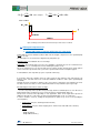
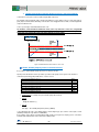
Sleep Function (related parameters: J150 (Hz), J151 (s))
Sleep function can be useful to stop one pump when the speed is below a rate where there is no flow
(pump doesn’t impel).
Once the demand frequency level below this rate (the frequency when the pump begins to move the water
but not enough to create a flow) is known, parameter J150 (Hz) should be set slightly higher than this
frequency.
Through this function, is possible to avoid possible mechanical problems that could (over time) damage
pump components or ‘boil’ the water with the wasted energy causing excess pressure and leaks. In
addition, stopping the pump when it’s not really needed means, obviously, Energy Saving.
So, Sleep Function will be applied if the inverter’s demand output frequency is lower than the ‘sleep’ level
stored in parameter J150 (Hz) and it stays at a lower level for a time longer than that specified in J151 (s).
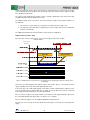
In Figure 1.2 and 1.3 sleep function is shown. The deceleration time to get to the “Stop Frequency” is
stored in F08 (s).
In order to have this function active, J149 must be different than 0. For additional details, refer to J149
parameter description.
Important: Sleep frequency (J150 (Hz)) must be lower than the wake-up frequency (J157 (Hz)) and must
be higher than the minimum frequency (F16=J119).
Wake-up function (related parameters J157 (Hz), J158, J159 (s))
Wake-up function is useful to start-up a pump again that previously was stopped by the sleep function.
In order to wake up a pump two condition must be accomplished:
MV ≥ J157 (Hz)
(J149=1,11,21)
Manipulated value (MV,
PID’s output) must be
greater than the level
stored in J157 (the current
MV value is shown on TPA1 according to
recommended setting)
Delay Time ≥ J159
(s)
(J149=2,12,22)
|SV – PV|≥ J158 (*)
(J149=2,12,22)
or...
The absolute value of the process error
(the subtraction between the process
value and the set point value ) must be
greater than the percentage in J158
and...
The percentage set in
J158 is kept or MV is
above J157 level longer
than the time specified
in J159
(*) J158 units depend on J105. Default setting is J158 units depend on PID Feedback 1 units (either C58,
C64 or C70, depending on the analogue input used as a feedback)
As one or two conditions have to be met in order for the pump to start, multiple start-ups due to pipe losses
can be avoided. So, we avoid waking up the pump unnecessarily or too often.
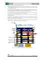
Figure 1.2 and 1.3 show how the pump goes to sleep mode and wakes up depending on J149 setting.
In addition, sleep frequency must be higher than minimum frequency (F16=J119)
7
Pump Control Quick Guide
With J149 = 1, 11, or 21 (frequency) selected
PV signal
SV: target value
J158: slow flowrate function cancel level 1
J160: slow flowrate function cancel level 2
MV frequency
F15: upper limiter
J157: initiation frequency
J150: slow flowrate function frequency
(Auto MV level)
Output frequency
J151:
slow flowrate
function elapse
time
J159:
on-delay timer
Initiation is not detected
because the time is in the
time range of the
initiation inhibition timer.
J156:
initiation inhibition timer
Initiation is performed
even though the time is
in the time range of the
initiation inhibition timer.
Slow flowrate
Slow flowrate
Figure 1.2: Speed control behaviour while sleep and wake-up functions are enabled and J14=1,11 or 21.
Figure 1.3: Speed control behaviour while sleep and wake-up functions are enabled and J14=2, 12 or 22.
8
Pump Control Quick Guide
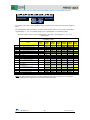
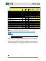
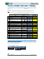
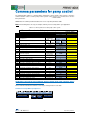
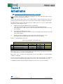
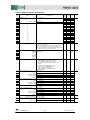
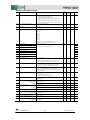
The following table (table 1.1), called “Common parameters to the all pump control systems”, shows the
common parameters to all pump control systems using
, these are known as the basic
parameters.
In other chapters, Specific Parameters’ table will be shown. These parameters will depend on the chosen
control system.
Note: The following values are shown as an example and could not work properly in your application.
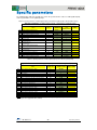
Table 1.1: Common parameters to all pump control systems
Common Parameters to all pump control systems
Name
F02
F07
F08
F11
Run command
Acceleration Time 1
Deceleration Time 1
Electronic Thermal Overload protection. Overload
detection Level
F12
Electronic Thermal Overload protection. Time constant
F15
F16
E62
C64
Frequency Limiter. High
Frequency Limiter. Low
Terminal [C1] extended function
Analog input adjustment for terminal [C1]. Display unit
C65
Analog input adjustment for terminal [C1] (max. scale)
K10
K16
K17
P01
Main monitor display item selection
Sub monitor 1 display item selection
Sub monitor 2 display item selection
Motor. Number of Poles
P02
Motor. Rated capacity
P03
Motor. Rated current
H91
J101
J110
J111
J118
J119
Current input wire break detection
PID Control 1. Mode Selection
PID Control 1. Gain P
PID Control 1. Integral time
PID Control 1. Upper limit of PID process output
PID Control 1. Lower limit of PID process output
J149
Slow flow rate stop function. Mode selection
J150
Slow flow rate stop function. Sleep frequency
Slow flow rate stop stop function. Sleep frequency level
latency
Slow flow rate stop function. Wake-up frequency
Slow flow rate stop function. Cancel deviation level 1
Slow flow rate stop function. Cancel delay timer
J151
J157
J158
J159
Default setting
Example’s Value
0
20.00 s
20.00 s
100% of the motor
rated current
5.0 min
10.0 min
(22kW or
(30kW or
below)
above)
70.0 Hz
0.0 Hz
0
2: %
1
3.00 s
3.00 s
+ 100.00
0: Speed monitor
13: Output current
19: Input power
4
Rated Capacity
Standard Motor
Rated Current
Standard Motor
0.0 s
0
0.100
0.0 s
Inherit
Inherit
0
Auto
User’s Value
13.0 A
5 min
50.0 Hz
25.0 Hz
5
44: bar
Transducer’s
pressure
51: PV
50: SV
1: Fout1
4
5.5 kW
13.0 A
0.5 s
1
2.500
0.2 s
Inherit
Inherit
1: Manual operation
(stop judgement MV)
35.0 Hz
0s
15 s
0 Hz
OFF
0s
38.0 Hz
0,5 bar
1s
CONDITIONS TO ACHIEVE GOOD CONTROL WITH A SINGLE PUMP
If it’s necessary to use a different parameter set-up to that shown in the above “Example Values” column,
please bear in mind the following conditions:
Sleeping/ Wake-up frequency Conditions
9
Pump Control Quick Guide
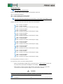
COMMON PARAMETERS DESCRIPTION
Basic Function
F02: Run Command
This function code defines the way in what the “RUN” signal will be given to the inverter in order to start
the pressure control.
Usually, “RUN Command” is sent to the inverter by means of the digital input (F02 = 1). That is, switching
on FWD or REV (control terminals in the inverter) digital inputs enables the inverter output.
A RUN command can be also activated by means of the TP-A1 keypad, pushing FWD or REV buttons.
F07: Acceleration Time 1
F08: Deceleration Time 1
These acceleration/deceleration ramps are used in two cases:
1.
After the RUN Command is ON, F07 ramp is used to achieve the frequency in F16 or J119 (the
biggest one of both values).
When the RUN Command is switched OFF, F08 value defines the deceleration ramp to go from the
current frequency to the stop frequency (F25).
At every change of output frequency, even due to the PID output change.
2.
These ramps are also used when the inverter is connected/disconnected from the commercial
power supply if function codes J455 and J458 are set to 0.00 (please refer to the corresponding
diagrams in the following chapters).
F11: Electronic Thermal Overload Protection. Overload detection level
F12: Electronic Thermal Overload Protection. Thermal time constant
By means of these two parameters is possible to adjust the overload protection function. Normally, F11 will
be adjusted to the motor’s rated current and F12 to 5 minutes.
F15: Frequency Limiter. High
F16: Frequency Limiter. Low
These two parameters define the frequency limits, and the inverter will never go outside of these limits
during pump control.
It’s normal to adjust the parameters F15, J118 and F03 with the same value.
Equally, F16 should be equal to J119, too.
Inputs Set-up
E62: Terminal [C1] extended function
This parameter can be used to select the function for analog input C1.
Usually this parameter is set to E62 = 5, this setting will define the [C1] analog input as PID Feedback
(pressure transducer).
Motor Map
P01: Motor. Number of poles
P02: Motor. Rated Capacity
P03: Motor. Rated Current
In these parameters must be stored the number of poles, rated capacity and rated current as are shown in
the motor’s nameplate.
10
Pump Control Quick Guide
Special Functions
H91: Current input wire break detection
Disconnection of pressure sensor (cable failure).
When a value is stored in parameter H91 (between 0.1 and 60.0 seconds) the inverter will generate an
alarm (CoF) when it notices that C1 signal current is missing (C1 current < 2mA) during a time longer than
the value in H91.
H91 = OFF function disabled.
H91 ≠ 0 function enabled.
PID and pump control
J101: PID control 1. Mode selection
When J101 = 1 and the error between Set Point and Process Value is positive (SP - PV > 0), the PID
controller makes a positive output action control (increasing MV). Alternatively when the error between Set
Point and Process Value is negative (SP - PV < 0), the PID controller makes a negative output action
control (decreasing MV).
Alternatively, if J101 = 2 and the error between Set Point and Process Value is negative (SP – PV < 0) the
PID controller makes a positive output action control (increasing MV). Alternatively when the error between
Set Point and Process Value is positive (SP - PV > 0), the PID controller makes a negative output action
control (decreasing MV).
J110: PID Control 1. P Gain
This parameter is used to set the PID controller’s proportional gain (P). This parameter must be adjusted
because its value depends on the application.
A high P value produces a PID controller’s quick response. Otherwise, a low P-value produces a slow
response.
J111: PID Control 1. Integral Time
This parameter is used to adjust PID’s integral time (I). This parameter must be adjusted because its value
depends on the application.
A high integral time value produces a PID slow response. Otherwise, a low I value produces a quicker
response.
J118: PID control 1. Upper limit of PID process output
J119: PID control 1. Lower limit of PID process output
These parameters specify upper and lower limit process output values.
We set J118 = F15 = F03 and J119 = F16.
PID Control 2 is also available. Each function explained for PID Control 1 has an equivalent function in PID
Control 2. For additional information, refer to FRENIC-AQUA User Manual.
11
Pump Control Quick Guide
Mono-regulated pump control (Mono-joker)
1 inverter driven pump
Necessary digital outputs
Do we need the optional relay card
installed?
1
NO
1 auxiliary pump
(ON / OFF)
+
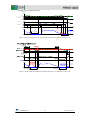
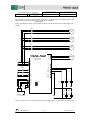
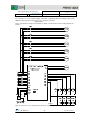
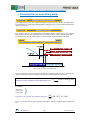
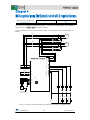
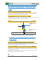
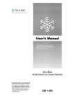
The schematic for a mono-regulated pump control with 1 regulated pump + 1 auxiliary pump by means of
the
inverter is as follows:
Please, pay attention to the pressure transducer’s wiring, connected to the inverter’s analog input C1 (4 –
20 mA).
KM1
AUXILIARY
PUMP
U
V
W
MONO-REGULATED PUMP
1 REGULATED PUMP
+ 1 AUXILIARY PUMP
L1
L2
L3
REGULATED
PUMP
Y1
Y2
Y3
Y4
Y5A
Y5C
RMEN1
30A
X5
30B
PLC
30C
C1
PLC
C1
SW5
CMY
CM
-
+
11
A1
KM1
P
220VAC
E
A2
Pressure transducer
4-20 mA (Vcc 24V)
Figure 2.1: Schematic of a mono-regulated pump control with 1 regulated pump + 1 auxiliary pump.
12
Pump Control Quick Guide
Mono-regulated pump control (Mono-joker)
1 inverter driven pump
Necessary digital outputs
Do we need the optional relay card
installed?
2/3
NO
2/3 auxiliary pump
(ON / OFF)
+
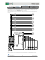
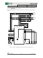
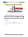
The schematic for a mono-regulated pump control with 1 regulated pump + 2/3 auxiliary pumps (using
additional relays) by means of the
inverter is as follows:
Please, pay attention to the pressure transducer’s wiring, connected to the inverter’s analog input C1 (4 –
20 mA)
KM3
AUXILIARY
PUMP 3
KM2
AUXILIARY
PUMP 2
KM1
AUXILIARY
PUMP 1
U
V
W
MONO-REGULATED PUMP
1 REGULATED PUMP
+ 3 AUXILIARY PUMPS
L1
L2
L3
REGULATED
PUMP
Y1
Y2
Y3
RMEN3
Y4
X3
Y5A
RMEN2
RMEN1
X4
Y5C
30A
X5
30B
PLC
30C
C1
PLC
C1
SW5
CMY
A1
A1
A1
KM1
RM2
RM3
A2
A2
A2
RM2
RM3
CM
-
+
11
P
E
Pressure transducer
4-20 mA (Vcc 24V)
220VAC
A1
A1
KM2
KM3
A2
A2
Figure 2.2: Schematic of a mono-regulated pump control with 1 regulated pump + 3 auxiliary pumps with external relays.
13
Pump Control Quick Guide
Mono-regulated pump control (Mono-joker)
1 inverter driven pump
Necessary digital outputs
2/3 auxiliary pump
(ON / OFF)
+
Do we need the optional relay card
installed?
YES
(OPC-G1-RY)
2/3
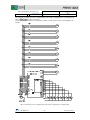
The schematic for a mono-regulated pump control with 1 regulated pump + 2/3 auxiliary pumps (using
OPC-G1-RY) by means of the
inverter is as follows:
Please, pay attention to the pressure transducer’s wiring, connected to the inverter’s analog input C1 (4 –
20 mA)
KM3
AUXILIARY
PUMP 3
KM2
AUXILIARY
PUMP 2
KM1
AUXILIARY
PUMP 1
U
V
W
MONO-REGULATED PUMP
1 REGULATED PUMP
+ 3 AUXILIARY PUMPS
L1
L2
L3
Y1
Y2
1A
OPC-G1-RY
(port-B)
RMEN3
X3
1B
1C
RMEN2
RMEN1
REGULATED
PUMP
2A
X4
2B
X5
2C
PLC
Y5A
Y5C
C1
PLC
C1
30A
SW5
30B
CMY
30C
CM
-
+
11
P
E
A1
A1
A1
KM1
KM2
KM3
A2
A2
A2
220VAC
Pressure transducer
4-20 mA (Vcc 24V)
Figure 2.3: Schematic of a mono-regulated pump control with 1 regulated pump + 3 auxiliary pumps with relay option card.
14
Pump Control Quick Guide
Mono-regulated pump control (Mono-joker)
1 inverter driven pump
+
Necessary digital outputs
Do we need the optional relay card
installed?
4/5
NO
4/5 auxiliary pump
(ON / OFF)
The schematic for a mono-regulated pump control with 1 regulated pump +4/5 auxiliary pumps (using
additional relays) by means of the
inverter is as follows:
Please, pay attention to the pressure transducer’s wiring, connected to the inverter’s analog input C1 (4 –
20 mA)
Figure 2.4: Schematic of a mono-regulated pump control with 1 regulated pump + 5 auxiliary pumps with external relays.
15
Pump Control Quick Guide
Mono-regulated pump control (Mono-joker)
1 inverter driven pump
+
Necessary digital outputs
4/5 auxiliary pump
(ON / OFF)
4/5
Do we need the optional relay card
installed?
YES
(OPC-G1-RY2)
The schematic for a mono-regulated pump control with 1 regulated pump +4/5 auxiliary pumps (using
OPC-G1-RY2) by means of the
inverter is as follows:
Please, pay attention to the pressure transducer’s wiring, connected to the inverter’s analog input C1 (4 –
20 mA)
Figure 2.5: Schematic of a mono-regulated pump control with 1 regulated pump + 5 auxiliary pumps with option card.
16
Pump Control Quick Guide
Mono-regulated pump control (Mono-joker)
1 inverter driven pump
+
Necessary digital outputs
8 auxiliary pump
(ON / OFF)
8
Do we need the optional relay card
installed?
YES
(OPC-G1-RY2)
The schematic to implement a mono-regulated pump control with 1 regulated pump + 8 auxiliary pumps
with a
inverter is as follows:
Please, pay attention on the pressure transducer’s wiring, connected to the inverter’s analog input C1 (4 –
20 mA).
Figure 2.6: Schematic for a mono-regulated pump control with 1 regulated pump + 8 auxiliary pumps
17
Pump Control Quick Guide
Mono-regulated pump control involves a pump exclusively driven by the inverter and other(s) pump(s),
working in “On-Off control” mode and directly connected to the commercial power supply.
The inverter will connect/disconnect the auxiliary pump(s) to the commercial power supply, in order to
achieve the desired pressure.
By means of the TP-A1 keypad, digital input or analog command, the desired system pressure will be set.
Then, the inverter will modify the speed of the regulated pump between the minimum frequency (J119 =
F16) and a maximum frequency (J118 = F15 = F03), keeping the pressure under control.
The inverter’s PID control 1 must be activated (J101) and adjusted accordingly, ensuring the inverter’s
response is what the installation requires all the time.
PID control 1 action can be adjusted by means of function codes J110 and J111 (proportional gain and
integral time).
Connection/Disconnection of an auxiliary pump is shown in Figure 2.5, with all the related function codes.
Figure 2.7: Speed pattern with mono-regulated pump control. The Auxiliary pump is connected and disconnected
18
Pump Control Quick Guide
The requirements or conditions to activate an auxiliary pump are described below:
• Connection of an auxiliary pump
If the regulated pump’s output frequency is higher than the level established by J450 during the time
specified in J451, the inverter will understand that using the regulated pump is not enough to maintain the
required pressure, and the inverter is ready to connect an auxiliary pump to the commercial power supply.
When the conditions above are accomplished, the inverter will decrease the output frequency of the
regulated pump to the value stored in J457, by means of the deceleration ramp in J455. Once the
frequency level J457 is achieved, the PID controller will be activated again.
The frequency level when the auxiliary pumps are connected is defined in function code J456.
Figure 2.8: Auxiliary pump’s connection
The exact frequency level where the inverter connects the auxiliary pumps to the commercial power supply
is specified by means of the function code J456. The equation that defines this level is:
Frequency for the connection of the auxiliary pumps (Hz)
J 456
=
× ( J 118 − J 119) + J 119
100
As an example:
J456 = 50 %
J118 = 50 Hz
J119 = 25 Hz
Frequency for the connection of the auxiliary pumps (Hz)
50
=
× (50 − 25) + 25 = 37,5Hz
100
In this case, the connection of the auxiliary pumps happens when the regulated pump is turning at 37.5 Hz.
19
Pump Control Quick Guide
The requirements or conditions to deactivate an auxiliary pump are described below:
• Disconnection of an auxiliary pump
If the output frequency level of the regulated pump gets lower than the value stored in J452 during a time
longer than J453, the inverter will understand that the auxiliary pump is no longer needed and will begin a
disconnection process.
If the conditions above are accomplished, the inverter will increase the output frequency of the regulated
pump until the frequency level specified by function code J460, by means of the acceleration ramp J458.
The frequency level when the auxiliary pumps are disconnected is defined by function code J459.
Figure 2.9: Disconnection of an auxiliary pump
The exact frequency level where the inverter disconnects the auxiliary pumps from the commercial power
supply is specified by means of the function code J459. The equation that defines this level is:
Frequency for the connection of the auxiliary pumps (Hz)
J 459
=
× ( J 118 − J 119) + J 119
100
For example:
J459 = 40 %
J118 = 50 Hz
J119 = 25 Hz
Frequency for disconnection of the auxiliary pumps (Hz)
40
=
× (50 − 25) + 25 = 35Hz
100
In this case, the disconnection of the auxiliary pumps happens when the regulated pump is turning at 35
Hz.
20
Pump Control Quick Guide
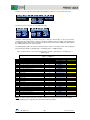
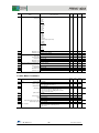
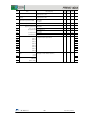
The following table (Table 2.1), “Common parameters to all the pump control systems”, shows the
common parameters to all of the control systems using
inverter. These are known as the
basic parameters.
In addition to the following table, there is also a specific parameters table.
Note: The following values are shown as an example and may not necessarily work in your application
Table 2.1: Common parameters to all pump control systems
Common Parameters to all pump control systems
Name
F02
F07
F08
F11
Run command
Acceleration Time 1
Deceleration Time 1
Electronic Thermal Overload protection. Overload
detection Level
F12
Electronic Thermal Overload protection. Time constant
F15
F16
E62
C64
Frequency Limiter. High
Frequency Limiter. Low
Terminal [C1] extended function
Analog input adjustment for terminal [C1]. Display unit
C65
Analog input adjustment for terminal [C1] (max. scale)
K10
K16
K17
P01
Main monitor display item selection
Sub monitor 1 display item selection
Sub monitor 2 display item selection
Motor. Number of Poles
P02
Motor. Rated capacity
P03
Motor. Rated current
H91
J101
J110
J111
J118
J119
Current input wire break detection
PID Control 1. Mode Selection
PID Control 1. Gain P
PID Control 1. Integral time
PID Control 1. Upper limit of PID process output
PID Control 1. Lower limit of PID process output
J149
Slow flow rate stop function. Mode selection
J150
Slow flow rate stop function. Sleep frequency
Slow flow rate stop stop function. Sleep frequency level
latency
Slow flow rate stop function. Wake-up frequency
Slow flow rate stop function. Cancel deviation level 1
Slow flow rate stop function. Cancel delay timer
J151
J157
J158
J159
Default setting
Example’s Value
0
20.00 s
20.00 s
100% of the motor
rated current
5.0 min
10.0 min
(22kW or
(30kW or
below)
above)
70.0 Hz
0.0 Hz
0
2: %
1
3.00 s
3.00 s
+ 100.00
0: Speed monitor
13: Output current
19: Input power
4
Rated Capacity
Standard Motor
Rated Current
Standard Motor
0.0 s
0
0.100
0.0 s
Inherit
Inherit
0
Auto
User’s Value
13.0 A
5 min
50.0 Hz
25.0 Hz
5
44: bar
Transducer’s
pressure
51: PV
50: SV
1: Fout1
4
5.5 kW
13.0 A
0.5 s
1
2.500
0.2 s
Inherit
Inherit
1: Manual operation
(stop judgement MV)
35.0 Hz
0s
15 s
0 Hz
OFF
0s
38.0 Hz
0,5 bar
1s
CONDITIONS TO ACHIEVE GOOD CONTROL IN MONO-REGULATED PUMP CONTROL
If it’s necessary to use a different parameter set-up to that shown in the above “Example Values” column,
please bear in mind the following conditions:
Conditions for Sleep/Wake-up frequency
21
Pump Control Quick Guide
Conditions for the frequencies that define when auxiliary pumps are connected/disconnected
The function codes J450, J452 and J460 belong to specific function codes group and will be explained
below.
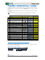
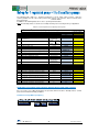
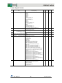
The following tables (Table 2.2 and 2.3) show the specific function codes for a good control system with 1
regulated pump + 1, 2, 3, 4 or 5 auxiliary pumps and 1 regulated pump + 6,7,8 auxiliary pumps:
Table 2.2: Function codes for mono-regulated pump control with 1 regulated pump + 1, 2, 3, 4 or 5
auxiliary pumps
Specific Function Codes , mono-regulated pump control with 1 regulated pump + 1, 2, 3, 4 or
5 auxiliary pumps
Name
E20 (o05)
E21 (o04)
E22 (o03)
E23 (o02)
E24 (o01)
J401
J411
J412
J413
J414
J415
J450
J451
J452
J453
J459
J456
J457
J460
Status Signal Assignment to Y1 (10)
Status Signal Assignment to Y2 (9)
Status Signal Assignment to Y3 (8)
Status Signal Assignment to Y4 (7)
Status Signal Assignment to Y5A/C (6)
Pump Control. Mode Selection
Motor 1 Mode
Motor 2 Mode
Motor 3 Mode
Motor 4 Mode
Motor 5 Mode
Start of commercial power-driven
motor.Frequency
Start of commercial power-driven
motor.Duration
Stop of commercial power-driven
motor.Frequency
Stop of commercial power-driven
motor.Duration
Motor Unmount switching level
Motor Mount Switching level
PID Start Frequency (Mount)
PID Start Frequency (Unmount)
Default
Setting
For 1
auxiliary
pump
For 2
auxiliary
pumps
For 3
auxiliary
pumps
For 4
auxiliary
pumps
For 5
auxiliary
pumps
0
1
2
7
15
0
0
0
0
0
0
0
1
2
7
161(M1_L)
1
1
0
0
0
0
0
1
2
163(M2_L)
161(M1_L)
1
1
1
0
0
0
0
1
165(M3_L)
163(M2_L)
161(M1_L)
1
1
1
1
0
0
0
167(M4_L)
165(M3_L)
163(M2_L)
161(M1_L)
1
1
1
1
1
0
169(M5_L)
167(M4_L)
165(M3_L)
163(M2_L)
161(M1_L)
1
1
1
1
1
1
999
48 Hz
48 Hz
48 Hz
48 Hz
48 Hz
0.00 s
5.00 s
5.00 s
5.00 s
5.00 s
5.00 s
999
30 Hz
30 Hz
30 Hz
30 Hz
30 Hz
0.00 s
1.00 s
1.00 s
1.00 s
1.00 s
1.00 s
0%
0%
0 Hz
0 Hz
50 %
50 %
40 Hz
39 Hz
50 %
50 %
40 Hz
39 Hz
50 %
50 %
40 Hz
39 Hz
50 %
50 %
40 Hz
39 Hz
50 %
50 %
40 Hz
39 Hz
User’s
setting
Note: The default setting for function code J457 and J460 (Inherit) may work properly in your installation
without adjusting it to the suggested value (40 Hz and 39 Hz respectively).
22
Pump Control Quick Guide
Table 2.3: Specific function codes for Mono-regulated pump control with 1 regulated pump + 6, 7, 8 auxiliary pumps
Specific Function Codes for mono-regulated pump control with 1 regulated pump + 6,7,8 auxiliary
pumps
Name
o01
o02
o03
o04
o05
o06
o07
E24
J401
J411
J412
J413
J414
J415
J416
J417
J418
J450
J451
J452
J453
J459
J456
J457
J460
J565
J466
Status Signal Assignment to 6 A/C (OPC-G1-RY2)
Status Signal Assignment to 7 A/C (OPC-G1-RY2)
Status Signal Assignment to 8 A/C (OPC-G1-RY2)
Status Signal Assignment to 9 A/C (OPC-G1-RY2)
Status Signal Assignment to 10 A/C (OPC-G1-RY2)
Status Signal Assignment to 11 A/C (OPC-G1-RY2)
Status Signal Assignment to 12 A/C (OPC-G1-RY2)
Status Signal Assignment to Y5A/C
Pump Control. Mode Selection
Motor 1 mode
Motor 2 mode
Motor 3 mode
Motor 4 mode
Motor 5 mode
Motor 6 mode
Motor 7 mode
Motor 8 mode
Start of commercial power-driven motor. Frequency
Start of commercial power-driven motor. Duration
Stop of commercial power-driven motor. Frequency
Stop of commercial power-driven motor. Duration
Motor Unmount switching Level
Motor Mount switching Level
PID Start Frequency (Mount)
PID Start Frequency (Unmount)
Auxiliary Motor (Frequency operation level)
Auxiliary Motor (Hysteresis width)
Default
Setting
For 6
auxiliary
pumps
For 7
auxiliary
pumps
For 8
auxiliary
pumps
10
6
25
26
28
36
37
15
0
0
0
0
0
0
0
0
0
999
0.00 s
999
0.00 s
0%
0%
0 Hz
0 Hz
50.0 Hz
1.0 Hz
161 (M1_L)
163 (M2_L)
165 (M3_L)
167 (M4_L)
169 (M5_L)
171 (M6_L)
37
15
1
1
1
1
1
1
1
0
0
48 Hz
5.00 s
30 Hz
1.00 s
50 %
50 %
40 Hz
39 Hz
47.0 Hz
8.0 Hz
161 (M1_L)
163 (M2_L)
165 (M3_L)
167 (M4_L)
169 (M5_L)
171 (M6_L)
173 (M7_L)
15
1
1
1
1
1
1
1
1
0
48 Hz
5.00 s
30 Hz
1.00 s
50 %
50 %
40 Hz
39 Hz
47.0 Hz
8.0 Hz
161 (M1_L)
163 (M2_L)
165 (M3_L)
167 (M4_L)
169 (M5_L)
171 (M6_L)
173 (M7_L)
175 (M8_L)
1
1
1
1
1
1
1
1
1
48 Hz
5.00 s
30 Hz
1.00 s
50 %
50 %
40 Hz
39 Hz
47.0 Hz
8.0 Hz
User’s value
Note: The default setting for function code J457 and J460 (0 Hz) may work properly in your installation
without adjusting it to the suggested value (40 Hz and 39 Hz respectively).
DESCRIPTION OF THE SPECIFIC FUNCTION CODES FOR MONO-REGULATED PUMP
CONTROL
Outputs Set-up
E20, E21, E24, E27, o01 to o07: Signal status assignment to 1 A/B/C (Y1 or Y3) 2 A/B/C (Y2 or
Y4), Y5A/C, 30A/B/C and 6 A/C to 12 A/C
Function codes E20, E21, E24, E27 and from o01 to o07 define the function that will be assigned to
terminals 1 A/B/C (Y1 or Y3), 2 A/B/C (Y2 or Y4), Y5A/C, 30A/B/C and from 6 A/C to 12 A/C respectively.
In a mono-regulated pump control system these outputs must be set in order to connect / disconnect the
auxiliary pumps to the commercial power supply (functions 161: pump 1 to commercial power supply, 163:
pump 2 to the commercial power supply, 165: pump 3 to commercial power supply and 167 pump 4 to
commercial power supply, 167: pump 4 to commercial power supply, 169: pump 5 to commercial power
supply, 171: pump 6 to commercial power supply, 173: pump 7 to commercial power supply, 175: pump 8
to commercial power supply).
23
Pump Control Quick Guide
PID and Pump control
J401: Pump control. Mode Selection
Function code J401 defines the type of pump control that will be performed.
J401 = 0 Pump Control Disabled
J401 = 1 Mono-regulated pump Control Enabled
J401 = 2 Multi-regulated pump Control Enabled
J411, J412, J413, J414, J415, J416, J417, J418: Motor 1 mode, Motor 2 mode, Motor 3 mode,
Motor 4 mode, Motor 5 mode, Motor 6 mode, Motor 7 mode, Motor 8 mode.
Function codes J411, J412, J413, J414, J415, J416, J417 and J418 define:
J411 = 0 Pump 1 unavailable
J411 = 1 Pump 1 available
J411 = 2 Pump 1 connected to commercial power supply
J412 = 0 Pump 2 unavailable
J412 = 1 Pump 2 available
J412 = 2 Pump 2 connected to commercial power supply
J413 = 0 Pump 3 unavailable
J413 = 1 Pump 3 available
J413 = 2 Pump 3 connected to commercial power supply
J414 = 0 Pump 4 unavailable
J414 = 1 Pump 4 available
J414 = 2 Pump 4 connected to commercial power supply
J415 = 0 Pump 5 unavailable
J415 = 1 Pump 5 available
J415 = 2 Pump 5 connected to commercial power supply
J416 = 0 Pump 6 unavailable
J416 = 1 Pump 6 available
J416 = 2 Pump 6 connected to commercial power supply
J417 = 0 Pump 7 unavailable
J417 = 1 Pump 7 available
J417 = 2 Pump 7 connected to commercial power supply
J418 = 0 Pump 8 unavailable
J418 = 1 Pump 8 available
J418 = 2 Pump 8 connected to commercial power supply
In normal operation, the mode to be used is 1.
The other modes can be useful in the following situations:
-
Mode 0: The pump will be omitted. Can be useful to disconnect, software disabled, a pump from
the pump control system, without modifying the current wiring.
-
Mode 2: Can be useful to check the rotation direction of the pump, because the pump will be
connected to the commercial power supply as soon as this mode is activated.
ATTENTION
If the mode 2 is set in any of the function codes J411 to J418, the corresponding pump will begin to rotate at
the speed defined by the commercial power supply. Take the necessary measures.
24
Pump Control Quick Guide
Necessary digital
outputs
Mono-regulated pump control (Mono-joker)
1 regulated
pump
+
8 auxiliary pumps
(On-Off control)
+
1 additional pump
(On-Off control)
9
Do we need the optional relay
card installed?
YES
(OPC-G1-RY2)
The schematic to implement a mono-regulated pump control with 1 regulated pump + 8 auxiliary pumps +
1 additional pump with a
inverter is as follows:
Please, pay attention on the pressure transducer’s wiring, connected to the inverter’s analog input C1 (4 –
20 mA).
Figure 3.1: Schematic for a mono-regulated pump control with 1 regulated pump + 8 auxiliary pumps + 1 additional
pump
25
Pump Control Quick Guide
This control system consists on a regulated pump controlled exclusively by the inverter and other 9 pumps
working in “On-Off control” mode connected directly to the commercial power supply (8 auxiliary pumps +
1 additional pump). The inverter will connect/disconnect the auxiliary pumps to the commercial power
supply in order to achieve the desired pressure.
The additional pump will be connected to the commercial power supply if the following two conditions are
fulfilled:
1.
All the auxiliary pumps that are enabled at this moment are connected to the commercial power
supply, and
2.
The regulated pump’s frequency is higher than the value stored in J465 (Hz).
The additional pump will be disconnected from the commercial power supply when:
Output frequency ≤ (J465 – J466)
Using this control, the
inverter is able to control up to 10 pumps.
Figure 3.2: Additional pump’s connection/disconnection diagram if all the auxiliary pumps are enabled
26
Pump Control Quick Guide
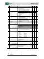
The following table (Table 3.1), called “Common parameters to all the pump control systems”, shows the
common parameters to all of the control systems using the
inverter, these are the basic
parameters.
Additional to the common function codes’ table, there is also a table with specific function codes.
Note: The following values are only an example, and may not necessarily work in your application.
Table 3.1: Common parameters to all the pump control systems
Common parameters to all the pump control systems
Name
F02
F07
F08
F11
RUN command
Acceleration time 1
Deceleration time 1
Electronic Thermal Overload protection. Overload
detection Level
F12
Electronic Thermal Overload protection. Time constant
F15
F16
C64
Frequency Limiter. High
Frequency Limiter. Low
Analog input adjustment for terminal [C1]. Display unit
C65
Analog input adjustment for terminal [C1] (max. scale)
K10
K16
K17
E62
P01
Main monitor display item selection
Sub monitor 1 display item selection
Sub monitor 2 display item selection
Terminal [C1] extended function
Motor. Number of poles
P02
Motor. Rated Capacity
P03
Motor. Rated Current
H91
J101
J110
J111
J118
J119
Current input wire break detection
PID Control 1. Mode selection
PID Control 1. Gain P
PID Control 1. Integral time I
PID Control 1. Upper limit of PID process output
PID Control 1. Lower limit of PID process output
J149
Slow flow rate stop function. Mode selection
J150
Slow flow rate stop function. Sleep frequency
Slow flow rate stop stop function. Sleep frequency level
latency
Slow flow rate stop function. Wake-up frequency
Slow flow rate stop function. Cancel deviation level 1
Slow flow rate stop function. Cancel delay timer
J151
J157
J158
J159
Default Setting
Example’s value
0
20.00 s
20.00 s
100% of the rated
motor current
5.0 min
10.0 min
(22kW or
(30kW or
below)
above)
70.0 Hz
0.0 Hz
2: %
1
3.00 s
3.00 s
+ 100.00
0: Speed monitor
13: Output current
19: Input power
0
4
Rated Capacity
standard motor
Rated current
standard motor
0.0 s
0
0.100
0.0 s
Inherit
Inherit
0
0 Hz
User’s Value
13.0 A
5 min
50.0 Hz
25.0 Hz
44: bar
Transducer’s
pressure
51: PV
50: SV
1: Fout
5
4
5.5 kW
13.0 A
0.5 s
1
2.500
0.2
Inherit
Inherit
1: Manual operation
(stop judgement MV)
35.0 Hz
30 s
15 s
0 Hz
0%
0s
38.0 Hz
0,5 bar
1s
CONDITIONS TO ACHIEVE GOOD CONTROL WITH A MONO-REGULATED PUMP CONTROL +
8 AUXILIARY PUMPS + 1 ADDITIONAL PUMP
If it’s necessary to use a different parameter set-up to that shown in the above “Example Values” column,
please bear in mind the following conditions:
Conditions for Sleep/Wake-up frequency
27
Pump Control Quick Guide
Conditions for the frequencies that define when auxiliary pumps are connected/disconnected
Conditions for the connection of the additional pump
Using this control topology, it can be necessary to delay the disconnection of the motor from the
commercial power supply (J453), in order to prevent the simultaneous disconnection of the auxiliary and
the additional pumps. That is, the first pump to be disconnected should be the additional pump and then
the auxiliary pump, but never at the same time.
The following table (Table 3.2) shows the specific function codes to successfully control a mono-regulated
pump control system with 1 regulated pump + 8 auxiliary pumps + 1 additional pump:
Table 3.2: Specific function codes for Mono-regulated pump control with 1 regulated pump + 8 auxiliary pumps + 1
additional pump
Specific Function Codes for mono-regulated pump control with 1 regulated pump + 8 auxiliary
pumps + 1 additional
Name
o01
o02
o03
o04
o05
o06
o07
E23
E24
J401
J411
J412
J413
J414
J415
J416
J417
J418
J450
J451
J452
J453
J459
J456
J457
J460
J465
J466
Status Signal Assignment to 6 A/C (OPC-G1-RY2)
Status Signal Assignment to 7 A/C (OPC-G1-RY2)
Status Signal Assignment to 8 A/C (OPC-G1-RY2)
Status Signal Assignment to 9 A/C (OPC-G1-RY2)
Status Signal Assignment to 10 A/C (OPC-G1-RY2)
Status Signal Assignment to 11 A/C (OPC-G1-RY2)
Status Signal Assignment to 12 A/C (OPC-G1-RY2)
Status Signal Assignment to Y4
Status Signal Assignment to Y5A/C
Pump Control. Mode Selection
Motor 1 mode
Motor 2 mode
Motor 3 mode
Motor 4 mode
Motor 5 mode
Motor 6 mode
Motor 7 mode
Motor 8 mode
Start of commercial power-driven motor. Frequency
Start of commercial power-driven motor. Duration
Stop of commercial power-driven motor. Frequency
Stop of commercial power-driven motor. Duration
Motor Unmount switching Level
Motor Mount switching Level
PID Start Frequency (Mount)
PID Start Frequency (Unmount)
Auxiliary Motor (Frequency operation level)
Auxiliary Motor (Hysteresis width)
Default Setting
Example’s value
10
6
25
26
28
36
37
7
15
0
0
0
0
0
0
0
0
0
999
0.00 s
999
0.00 s
0%
0%
0 Hz
0 Hz
50.0 Hz
1.0 Hz
161 (M1_L)
163 (M2_L)
165 (M3_L)
167 (M4_L)
169 (M5_L)
171 (M6_L)
173 (M7_L)
88 (AUX_L)
175 (M8_L)
1
1
1
1
1
1
1
1
1
48 Hz
5.00 s
30 Hz
1.00 s
50 %
50 %
40 Hz
39 Hz
47.0 Hz
8.0 Hz
User’s value
Note: The default setting for function code J457 and J460 (0 Hz) may work properly in your installation
without adjusting it to the suggested value (40 Hz and 39 Hz respectively).
28
Pump Control Quick Guide
DESCRIPTION OF SPECIFIC PARAMETERS FOR A MONO-REGULATED PUMP CONTROL + 8
AUXILIARY PUMPS + 1 ADDITIONAL PUMP
Outputs Set-up
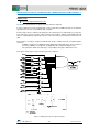
E23: Status Signal Assignment to (Y4)
The function code E23 defines the signal assigned to transistor output Y4.
In order to implement a mono-regulated pump control system with an additional pump, the Y4 terminal’s
signal must be set to 88, corresponding to AUX_L function.
If all the pumps that are enabled (using parameters J411-J418) have been activated (they are active due
to the state of the system), by means of AUX_L function it is possible to activate an extra digital output Y4
when the regulated pump’s output frequency raises above the frequency level defined in the function code
J465.
In this function, one pump is considered “enabled” when the two conditions below are accomplished at the
same time:
If MEN# is assigned to any digital input, this digital input must be ON (where # is the number of
the motor). If MEN# is not assigned to any digital input, this condition will always be true.
If the parameter, within J411-J418 range, corresponding to this pump is different from zero
In the picture below (Figure 3.3) this function logic block is depicted:
Figure 3.3: Additional pump function logic block diagram
29
Pump Control Quick Guide
Using function code J466 it is possible to define a hysteresis, for deactivating the pump below certain level
of frequency and in order to avoid the signal Y4 activating/deactivating constantly.
J465: Auxiliary Motor (Frequency operation level)
This function code defines the detection level where AUX_L function can be activated. That is, if the output
frequency is higher than this level, the output with the AUX_L function assigned (88) will be activated. The
level configured in J465 must be similar to the value of J450.
J466: Auxiliary Motor (Hysteresis width)
With this parameter it is possible to adjust the hysteresis level for the deactivation of the AUX_L
accordingly. The result of J465-J466 must be similar to the value of J452.
30
Pump Control Quick Guide
Multi-regulated pump Control (Multi-Joker)
Necessary digital outputs
2 Regulated pumps
4
Do we need the optional relay card
installed?
NO
The schematic to implement a multi-regulated pump control with 2 regulated pumps (Using additional
relays) by means of
inverter is as follows:
Please, pay attention on the pressure transducer’s wiring, connected to the inverter’s analog input C1 (4 –
20 mA).
KM2
REGULATED
PUMP 2
KV2
KM1
REGULATED
PUMP 1
KV1
U
V
W
MULTI-REGULATED PUMP
2 REGULATED PUMPS
Y1
L1
L2
L3
Y2
Y3
Y4
Y5A
RMEN2
RMEN1
Y5C
X4
30A
X5
30B
PLC
30C
C1
PLC
SW5
C1
CMY
CM
-
+
11
P
E
A1
A1
A1
A1
KV1
RM1
RV2
RM2
A2
A2
A2
A2
RM1
RV2
RM2
Pressure transducer
4-20 mA (Vcc 24V)
220VAC
A1
A1
A1
KM1
KV2
KM2
A2
A2
A2
Figure 4.1: Schematics of multi-regulated pump control with 2 regulated pumps (Using additional relays)
31
Pump Control Quick Guide
Multi-regulated pump Control (Multi-Joker)
Necessary digital outputs
2 Regulated pumps
4
Do we need the optional relay card
installed?
OPC-G1-RY2
The schematic to implement a multi-regulated pump control with 2 regulated pumps (Using OPC-G1-RY2)
inverter is as follows:
by means of
Please, pay attention on the pressure transducer’s wiring, connected to the inverter’s analog input C1 (4 –
20 mA).
KM2
REGULATED
PUMP 2
KV2
KM1
REGULATED
PUMP 1
KV1
U
V
W
MULTI-REGULATED PUMP
2 REGULATED PUMPS
OPC-G1-RY2
(Port-C)
L1
L2
L3
RMEN2
RMEN1
X4
X5
PLC
C1
PLC
SW5
C1
CMY
Y5A
Y5C
30A
30B
30C
CM
-
+
6A
6C
7A
7C
8A
8C
9A
9C
10A
10C
11A
11C
12A
12C
11
P
E
220VAC
A1
A1
A1
A1
KV1
KM1
KV2
KM2
A2
A2
A2
A2
Pressure transducer
4-20 mA (Vcc 24V)
Figure 4.2: Schematics of multi-regulated pump control with 2 regulated pumps (Using OPC-G1-RY2)
32
Pump Control Quick Guide
This control consists of 2 pumps regulated by the inverter.
In Multi-regulated pump Control, all of the system pumps are driven by means of the inverter. The inverter
controls the pump and connects/disconnects each pump to/from the commercial power supply according
to the application requirements.
By means of the TP-A1 keypad, digital inputs or analog command, the desired pressure will be set. Then,
the inverter will modify the regulated pump’s speed between the minimum frequency (J119 = F16) and the
maximum frequency (J118 = F15 = F03), in order to keep the pressure under control.
To do this, the PID control 1 that comes with the inverter must be activated (J101) and must be adjusted
properly, in order to provide an appropriate response in the installation.
The PID control 1 response can be modified by means of the function codes J110 and J111 (Proportional
gain and integral time).
The Figure 4.3 shows the regulation of two pumps, where, if the pressure’s demand increases and is not
possible to satisfy it with 1 pump, the inverter will connect the pump 1 to the commercial power supply and
will control of the second pump as a regulated one.
Similarly, if there is too much pressure, the inverter will disconnect pump 1 from the commercial power
supply and will continue working only with pump 2 as a regulated one.
Figure 4.3: Speed pattern of a Multi-regulated pump Control with 2 regulated pumps
33
Pump Control Quick Guide
Multi-regulated pump control (Multi-Joker)
Necessary digital outputs
3/4 regulated pumps
8/9
Do we need the optional relay card installed?
YES
(OPC-G1-RY2)
The schematic to implement a multi-regulated pump control with 4 regulated pumps by means of
inverter is as follows:
Please, pay attention on the pressure transducer’s wiring, connected to the inverter’s analog input C1 (4 –
20 mA).
KM4
REGULATED
PUMP 4
KV4
KM3
REGULATED
PUMP 3
KV3
KM2
REGULATED
PUMP 2
KV2
KM1
REGULATED
PUMP 1
KV1
MULTI-REGULATED PUMP
4 REGULATED PUMPS
U
V
W
Y1
Y2
L1
L2
L3
Y3
Y4
OPC-G1-RY2
(Port-C)
RMEN4
X2
RMEN3
X3
RMEN2
SW5
X4
RMEN1
C1
X5
PLC
C1
6A
6C
7A
7C
8A
8C
9A
9C
10A
10C
11A
11C
12A
12C
PLC
CMY
CM
11
-
+
Y5A
Y5C
30A
30B
30C
A1
KV1
P
E
A2
A1
KM1
A2
A1
KV2
A2
A1
KM2
A2
A1
KV3
A1
KM3
A2
A2
A1
KV4
A2
A1
KM4
A2
220VAC
Pressure transducer
4-20 mA (Vcc 24V)
Figure 4.4: Schematics of multi-regulated pump control with 4 regulated pumps
34
Pump Control Quick Guide
The following explanation describes the requirements or conditions to connect a regulated pump
to the commercial power supply, and to disconnect a pump from the commercial power supply:
• Connecting a regulated pump to commercial power
supply
If the regulated pump’s output frequency rises above the level stored in J450 during the time established in
J451, the inverter will understand that the regulated pump is not enough to maintain the required pressure
and will get ready to connect the pump to the commercial power supply.
If the conditions above are accomplished, the inverter will connect the regulated pump to the commercial
power supply and will take another pump of the system as a regulated one.
J451 (s)
J450 (Hz)
J454 (s)
Figure 4.5: Connection of a regulated pump to the commercial power supply.
• Disconnecting a regulated pump from commercial
power supply
If the regulated pump’s output frequency decreases under the level established in function code J452
during the time J453, the inverter will understand that is not necessary to keep a pump connected to the
commercial power supply and will get ready for its disconnection.
If the conditions above are accomplished, the inverter will increase the regulated pump’s output frequency
until the frequency stored in J460 using the acceleration time in J458. Once the frequency level achieves
this, the PID control 1 will be activated.
This behaviour can be useful to reduce the possible sudden pressure fluctuations that may occur when a
pump is disconnected from the commercial power supply.
35
Pump Control Quick Guide
Figure 4.6: Increase of the pump’s speed to disconnect the pump from the main supply
The exact point where the inverter will disconnect the pump from the main supply can be defined with
function code J459. The equation to find this point is:
J 459
Auxiliary pump’s disconnection frequency (Hz) = 100 × ( J 118 − J 119) + J 119
For example:
J459 = 40 %
J118 = 50 Hz
J119 = 25 Hz
Auxiliary pump’s disconnection frequency (Hz)
40
=
× (50 − 25) + 25 = 35Hz
100
In this case, when the regulated pump is rotating at 35 Hz, the inverter will disconnect the pump from the
main supply.
36
Pump Control Quick Guide
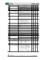
The following table (Table 4.1), called “Common Parameters to all the pump control systems”, shows the
common parameters to all the control systems using the
inverter, these are the basic
function codes.
In addition to the common function codes’ table, there is a table with the specific function codes.
Note: The following values are only an example, and may not necessarily work in your application.
Table 4.1: Common parameters to all pump control systems
Common Parameters to all the pump control systems
Name
F02
F07
F08
Default setting
Example’s Value
1
3.00 s
3.00 s
F12
Electronic Thermal Overload protection. Time constant
F15
F16
E62
C64
Frequency Limiter. High
Frequency Limiter. Low
Terminal [C1] extended function
Analog input adjustment for terminal [C1]. Display unit
0
20.00 s
20.00 s
100% of the motor
rated current
5.0 min
10.0 min
(22kW or
(30kW or
below)
above)
70.0 Hz
0.0 Hz
0
2: %
C65
Analog input adjustment for terminal [C1] (max. scale)
+ 100.00
P01
Motor. Number of Poles
P02
Motor. Rated capacity
P03
Motor. Rated current
H91
J101
J110
J111
J118
J119
Current input wire break detection
PID Control 1. Mode Selection
PID Control 1. Gain P
PID Control 1. Gain I
PID Control 1. Upper limit of PID process output
PID Control 1. Lower limit of PID process output
J149
Slow flow rate stop function. Mode selection
J150
Slow flow rate stop function. Sleep frequency
Slow flow rate stop stop function. Sleep frequency level
latency
Slow flow rate stop function. Wake-up frequency
Slow flow rate stop function. Cancel deviation level 1
Slow flow rate stop function. Cancel delay timer
Main monitor display item selection
Sub monitor 1 display item selection
Sub monitor 2 display item selection
F11
J151
J157
J158
J159
K10
K16
K17
Run command
Acceleration Time 1
Deceleration Time 1
Electronic Thermal Overload protection. Overload
detection Level
4
Rated Capacity
Standard Motor
Rated Current
Standard Motor
0.0 s
0
0.100
0.0 s
Inherit
Inherit
0
Auto
User’s Value
15.0 A
5.0 min
10.0 min
(22kW or
(30kW or
below)
above)
50.0 Hz
25.0 Hz
5
44: bar
Transducer’s
pressure
4
5.5 kW
15.0 A
0.5 s
1
2.500
0.2
Inherit
Inherit
1: Manual operation
(stop judgement MV)
35.0 Hz
0s
15 s
0 Hz
OFF
0s
0: Speed monitor
13: Output current
19: Input power
38.0 Hz
0,5 s
1s
51: PV
50: SV
51: PV
CONDITIONS TO ACHIEVE GOOD CONTROL IN A MULTI-REGULATED PUMP CONTROL WITH
2/3/4 REGULATED PUMPS
Conditions for Sleep/Wake-up frequencies
Conditions for the frequencies that define when auxiliary pumps are connected/disconnected
37
Pump Control Quick Guide
The following table (table 4.2 and table 4.3) shows the specific function codes for multi-regulated pump
control system with 2, 3 or 4 regulated pumps:
Table 4.2: Specific parameters for Multi-regulated pump control with 2 regulated pumps (with and without option)
Specific Parameters for Multi-regulated pump control with 2 regulated pumps
Name
E21
E22
E23
E24
J401
J411
J412
J450
J451
J452
J453
J459
J460
o01
o02
o03
Status Signal Assignment to Y2
Status Signal Assignment to Y3
Status Signal Assignment to Y4
Status Signal Assignment to Y5A/C
Pump Control. Mode Selection
Motor 1 Mode
Motor 2 Mode
Start of commercial power-driven
motor.Frequency
Start of commercial power-driven
motor.Duration
Stop of commercial power-driven
motor.Frequency
Stop of commercial power-driven
motor.Duration
Motor Unmount switching level
PID Start Frequency (Unmount)
Status Signal Assignment to Y6A/C
Status Signal Assignment to Y7A/C
Status Signal Assignment to Y8A/C
Default
value
For 2 regulated
pumps
(w/o OPC-G1-RY2)
For 2 regulated
pumps
(with OPC-G1-RY2)
1
2
7
15
0
0
0
163 (M2_L)
162 (M2_I)
161 (M1_L)
160 (M1_I)
2
1
1
160 (M1_I)
2
1
1
999
48 Hz
48 Hz
0.00 s
5.00 s
5.00 s
999
30 Hz
30 Hz
0.00 s
1.00 s
1.00 s
0%
0 Hz
10
6
25
50 %
39 Hz
-
50 %
39 Hz
161 (M1_L)
162 (M2_I)
163 (M2_L)
User’s
Value
Table 4.3: Specific parameters for Multi-regulated pump control with 4 regulated pumps
Specific Parameters for Multi-regulated pump control with 3/4 regulated pumps
Name
E24
J401
J411
J412
J413
J414
J450
J451
J452
J453
J459
J460
o01
o02
o03
o04
o05
o06
o07
Default value
For 4 regulated pumps
(with OPC-G1-RY2)
15
0
0
0
0
0
999
0.00 s
999
0.00 s
0%
0 Hz
10
6
25
26
28
36
37
160 (M1_I)
2
1
1
1
1
48 Hz
5.00 s
30 Hz
1.00 s
50 %
39 Hz
161 (M1_L)
162 (M2_I)
163 (M2_L)
164 (M3_I)
165 (M3_L)
166 (M4_I)
167 (M4_L)
Status Signal Assignment to Y5A/C
Pump Control. Mode Selection
Motor 1 Mode
Motor 2 Mode
Motor 3 Mode
Motor 4 Mode
Start of commercial power-driven motor.Frequency
Start of commercial power-driven motor.Duration
Stop of commercial power-driven motor.Frequency
Stop of commercial power-driven motor.Duration
Motor Unmount switching level
PID Start Frequency (Unmount)
Status Signal Assignment to Y6A/C
Status Signal Assignment to Y7A/C
Status Signal Assignment to Y8A/C
Status Signal Assignment to Y9A/C
Status Signal Assignment to Y10A/C
Status Signal Assignment to Y11A/C
Status Signal Assignment to Y12A/C
User’s Value
Note: The default setting for function code J460 (0 Hz) may work properly in your installation without
adjusting it to the suggested value (39 Hz).
38
Pump Control Quick Guide
SPECIFIC PARAMETERS DESCRIPTION
PID and pump control
J401: Pump control. Mode selection
The function code J401 defines which type of pump control is going to be used
J401 = 0 Pump control disabled
J401 = 1 Mono-regulated pump control enabled
J401 = 2 Multi-regulated control enabled
J411, J412, J413, J414: Motor 1 mode, Motor 2 mode, Motor 3 mode, Motor 4 mode.
The function codes J411, J412, J413, J414 define:
J411 = 0 pump 1 unavailable
J411 = 1 pump 1 available
J411 = 2 pump 1 connected to the commercial power supply
J412= 0 pump 2 unavailable
J412 = 1 pump 2 available
J412 = 2 pump 2 connected to the commercial power supply
J413 = 0 pump 3 unavailable
J413 = 1 pump 3 available
J413 = 2 pump 3 connected to the commercial power supply
J414 = 0 pump 4 unavailable
J414 = 1 pump 4 available
J414 = 2 pump 4 connected to the commercial power supply
In normal operation, the mode to be used is 1.
The other modes can be useful for:
-
Mode 0: The pump is omitted. Can be useful to disconnect, software disable, a pump from the
system without modifying the wires.
-
Mode 2: Can be useful to check the rotation direction of the pumps, because they will be
connected to the commercial power supply as soon as this mode is activated.
ATTENTION
If mode 2 is set to any of the parameters from J411 to J414, the corresponding pump will be turned on and will
rotate at the speed marked by the commercial power supply. Take all necessary precautions.
SPCECIFIC PARAMETERS DESCRIPTION HAVING OPTIONAL CARD RELAY INSTALLED
(OPC-G1-RY2)
PID and pump control
o01, o02, o03, o04, o05,o06 and o07: Status Signal Assignment to 6 A/C, 7 A/C, 8 A/C, 9A/C,
10A/C, 11A/C, 12A/C (modifying these function codes only makes sense when the OPC-G1-RY2
option card is installed in the inverter)
The function code o01, o02, o03, o04, o05, o06, o07 define the signal assignment to the outputs 6 A/C, 7
A/C, 8 A/C, 9A/C, 10A/C, 11A/C, 12A/C of the OPC-G1-RY2 option relay card.
In Multi-regulated pump control with 2, 3 or 4 regulated pumps these digital outputs must be set correctly
in order to connect/disconnect the 2, 3 or 4 pumps to the inverter or to the commercial power supply
(function 160: motor 1 inverter-driven, function 161: motor 1, commercial-power driven, function 162: motor
2 inverter-driven, function 163: motor 2 commercial-power driven, function 164: motor 3 inverter-driven and
function 165: motor 3 commercial-power driven, function 166: motor 4 inverter-driven and function 167:
motor 4 commercial-power driven).
39
Pump Control Quick Guide
Necessary digital outputs
Multi-regulated pump Control (Multi-Joker)
4 regulated pumps
1 additional pump
(“On-Off control”)
+
Do we need the optional relay card
installed?
YES
(OPC-G1-RY2)
9
The schematic for a multi-regulated pump control with 4 regulated pumps + 1 additional pump by means of
the
inverter is as depicted in figure 5.1.
Please, pay attention on the pressure transducer’s wiring, connected to the inverter’s analog input C1 (4 –
20 mA).
KA
ADDITIONAL
PUMP
KM4
REGULATED
PUMP 4
KV4
KM3
REGULATED
PUMP 3
KV3
KM2
REGULATED
PUMP 2
KV2
KM1
REGULATED
PUMP 1
KV1
MULTI-REGULATED PUMP
4 REGULATED PUMPS
+ 1 ADDITIONAL PUMP
U
V
W
Y1
Y2
L1
L2
L3
Y3
OPC-G1-RY2
(Port-C)
RMEN4
X2
RMEN3
X3
RMEN2
SW5
X4
RMEN1
C1
X5
PLC
C1
RA
Y4
220VAC
A1
A1
RA
6A
6C
7A
7C
8A
8C
9A
9C
10A
10C
11A
11C
12A
12C
KA
A2
A2
PLC
CMY
CM
11
-
+
Y5A
Y5C
30A
30B
30C
A1
KV1
P
E
A2
A1
KM1
A2
A1
KV2
A2
A1
KM2
A2
A1
KV3
A2
A1
KM3
A2
A1
KV4
A2
A1
KM4
A2
220VAC
Pressure transducer
4-20 mA (Vcc 24V)
Figure 5.1: Schematic for multi-regulated pump control with 4 regulated pumps + 1 additional pump
40
Pump Control Quick Guide
In Multi-regulated pump Control, all the system pumps are regulated by means of the inverter. The inverter
controls the pump and connects/disconnects each pump to/from the commercial power supply according
to the application requirements.
The control system explained in this chapter consists of 4 pumps regulated by means of the inverter plus
an additional pump working in “On-Off control” mode.
The additional pump will be connected to the commercial power supply if the following conditions are
accomplished:
1.
Two of the three system pumps are connected to the commercial power supply, and
2.
The frequency of the pump that is regulated by the inverter is higher than the level configured in
function code J465 (Hz).
The additional pump will be disconnected from the commercial power supply when:
Output frequency ≤ (J465 – J466)
By means of this control system,
inverter is able to control up to 5 pumps.
t
ADDITIONAL PUMP ON
ON
ON
ON
ON
Figure 5.2: Additional pump connection/disconnection diagram if all the regulated pumps which are enabled are also
active/playing
Note: In this case Active/playing means that the pump is either inverter driven or connected to the mains
supply, depending on the state of the multi-regulated pump control.
In the same way as the multi-regulated pump control with 2,3 and 4 regulated pumps (chapter 4), if the
pressure demand cannot be satisfied with only one pump, the inverter will connect it to the commercial
power supply and pump 2 will become the new regulated pump.
If there is still not enough pressure, pump 2 will be connected to the main supply and pump 3 will become
the new regulated pump. Same philosophy is used for the case of 4 pumps.
If there is still not enough pressure, the additional pump will be finally turned on.
But, if the pressure is too high, the inverter will disconnect the pumps connected to the commercial power
supply.
41
Pump Control Quick Guide
The following table (Table 5.1), called “Common parameters to all the pump control systems”, shows the
common function codes to all the pump control systems using
inverter, these are the
basic parameters.
Additional to the common parameters table, there is also a specific parameters table.
Note: The following values are only an example, and may not necessarily work in your application.
Table 5.1: Common parameters to all the pump control systems
Common Parameters to all the pump control systems
Name
F02
F07
F08
Default setting
Example’s Value
1
3.00 s
3.00 s
F12
Electronic Thermal Overload protection. Time constant
F15
F16
E62
C64
Frequency Limiter. High
Frequency Limiter. Low
Terminal [C1] extended function
Analog input adjustment for terminal [C1]. Display unit
0
20.00 s
20.00 s
100% of the motor
rated current
5.0 min
10.0 min
(22kW or
(30kW or
below)
above)
70.0 Hz
0.0 Hz
0
2: %
C65
Analog input adjustment for terminal [C1] (max. scale)
+ 100.00
P01
Motor. Number of Poles
P02
Motor. Rated capacity
F11
Run command
Acceleration Time 1
Deceleration Time 1
Electronic Thermal Overload protection. Overload
detection Level
P03
Motor. Rated current
H91
J101
J110
J111
J118
J119
Current input wire break detection
PID Control 1. Mode Selection
PID Control 1. Gain P
PID Control 1. Gain I
PID Control 1. Upper limit of PID process output
PID Control 1. Lower limit of PID process output
J149
Slow flow rate stop function. Mode selection
J150
Slow flow rate stop function. Sleep frequency
Slow flow rate stop stop function. Sleep frequency level
latency
Slow flow rate stop function. Wake-up frequency
Slow flow rate stop function. Cancel deviation level 1
Slow flow rate stop function. Cancel delay timer
Main monitor display item selection
Sub monitor 1 display item selection
Sub monitor 2 display item selection
J151
J157
J158
J159
K10
K16
K17
4
Rated Capacity
Standard Motor
Rated Current
Standard Motor
0.0 s
0
0.100
0.0 s
Inherit
Inherit
0
Auto
User’s Value
15.0 A
5.0 min
10.0 min
(22kW or
(30kW or
below)
above)
50.0 Hz
25.0 Hz
5
44: bar
Transducer’s
pressure
4
5.5 kW
15.0 A
0.5 s
1
2.500
0.2
Inherit
Inherit
1: Manual operation
(stop judgement MV)
35.0 Hz
0s
15 s
0 Hz
OFF
0s
0: Speed monitor
13: Output current
19: Input power
38.0 Hz
0,5 s
1s
51: PV
50: SV
51: PV
CONDITIONS TO ACHIEVE GOOD CONTROL IN MULTI-REGULATED PUMP CONTROL WITH 4
REGULATED PUMPS + 1 ADDITIONAL PUMP
Please follow the instructions below if it is necessary to change function codes data:
Conditions for Sleep/Wake-up frequencies
42
Pump Control Quick Guide
Conditions for the frequencies than define when auxiliary pumps are connected/disconnected
Conditions for the connection of an additional pump
With this topology, it may be necessary to extend the disconnection time of the motor from the commercial
power supply (J453), to prevent that the additional and the regulated pumps could be disconnected at the
same time. That is, the additional pump must be the first one to be disconnected, and then the regulated
pump, but never at the same time.
The following table (Table 5.2) shows the specific parameters for multi-regulated pump control system with
4 regulated pumps + 1 additional pump:
Table 5.2: Specific parameters of multi-regulated pump control with 4 regulated pumps + 1 additional pump
Specific Parameters for Multi-regulated pump control with 4 regulated pumps + 1
additional pump
Name
E20
E24
J401
J411
J412
J413
J414
J450
J451
J452
J453
J459
J460
J465
J466
o01
o02
o03
o04
o05
o06
o07
Status Signal Assignment to Y1
Status Signal Assignment to Y5A/C
Pump Control. Mode Selection
Motor 1 Mode
Motor 2 Mode
Motor 3 Mode
Motor 4 Mode
Start of commercial power-driven motor.Frequency
Start of commercial power-driven motor.Duration
Stop of commercial power-driven motor.Frequency
Stop of commercial power-driven motor.Duration
Motor Unmount switching level
PID Start Frequency (Unmount)
Auxiliary Motor (Frequency operation level)
Auxiliary Motor (Hysteresis width)
Status Signal Assignment to Y6A/C
Status Signal Assignment to Y7A/C
Status Signal Assignment to Y8A/C
Status Signal Assignment to Y9A/C
Status Signal Assignment to Y10A/C
Status Signal Assignment to Y11A/C
Status Signal Assignment to Y12A/C
Default value
For 4 regulated pumps
(with OPC-G1-RY2)
0
15
0
0
0
0
0
999
0.00 s
999
0.00 s
0%
0 Hz
50.0 Hz
1.0 Hz
10
6
25
26
28
36
37
88 (AUX_L)
160 (M1_I)
2
1
1
1
1
48 Hz
5.00 s
30 Hz
1.00 s
50 %
39 Hz
47.0 Hz
8.0 Hz
161 (M1_L)
162 (M2_I)
163 (M2_L)
164 (M3_I)
165 (M3_L)
166 (M4_I)
167 (M4_L)
User’s Value
Note: The default setting for function code J460 (0 Hz) may work properly in your installation without
adjusting it to the suggested value (39 Hz).
43
Pump Control Quick Guide
SPECIFIC PARAMETERS DESCRIPTION
Outputs Set-up
E20: Status Signal Assignment to Y1 (output terminals)
The function code E20 defines the signal assigned to transistor output Y1.
In order to implement a multi-regulated pump control system with an additional pump, the Y1 terminal’s
signal must be set to 88, corresponding to AUX_L function.
If all the pumps that are enabled (using parameters J411-J413) have been activated (they are active due
to the sate of the system), by means of AUX_L function it is possible to activate an extra digital output Y1
when the regulated pump’s output frequency is higher than the frequency level defined in the function code
J465.
In this function, one pump is considered “enabled” when the two conditions below are accomplished at the
same time:
If MEN# is assigned to any digital input, this digital input must be ON (where # is the number of
the motor). If MEN# is not assigned to any digital input, this condition will always be true.
If the parameter, within J411-J413 range, corresponding to this pump is different from zero
In the picture below (Figure 5.3) this function logic block is depicted:
Figure 5.3: Additional pump function logic block diagram
44
Pump Control Quick Guide
Using function code J466 it is possible to define a hysteresis, for deactivating the pump below certain level
of frequency and in order to avoid the signal Y1 activating/deactivating constantly.
J465: Auxiliary Motor (Frequency operation level)
This function code defines the detection level where AUX_L function can be activated. That is, if the output
frequency is higher than this level, the output with the AUX_L function assigned (88) will be activated. The
level configured in J465 must be similar to the value of J450.
J466: Auxiliary Motor (Hysteresis width)
With this parameter it is possible to adjust the hysteresis level for the deactivation of the AUX_L
accordingly. The result of J465-J466 must be similar to the value of J452.
45
Pump Control Quick Guide
Dry Pump function (Related function codes -> J176~J180)
Target: to make the inverter enter a STOP state, displaying an error code, when motor torque decreases
below a set level for a specified period of time.
Pressure can decrease due to factors such as water leakage or impeller damages. By means of a
parameter, an action done by inverter can be selected. The possible actions are stopping or just warning.
Dry pump protection becomes active when all of the conditions (from (1) to (3)) are satisfied and the
detection timer (J180) setting time elapses.
(1)
Output frequency detection (Output frequency ≥ upper limiter)
(F03, F15, J118, E61 to E63 = 13: lowest frequency among upper limit frequencies)
When pump dries off, output frequency is kept at the upper limiter during operations because the
pressure drops.
(2)
Current detection (Output current < J177)
When pump dries off, output current decreases due to the fact that pump load reduces caused by
water volume reduction.
(3)
Deviation detection (Feedback value (PV) < PID control command value (SV) – J178)
When pump dries off, feedback values (PV) decreases because air entrance.
In table 6.1, related parameters are shown:
Table 6.1 Specific parameters for Dry Pump function
Specific Parameters Dry pump function
Name
Default setting
Example’s value
0: Disabled
1: Alarm
Half of motor rated
current
10%
0: Disabled
0
J176
Dry pump protection. Input selection.
J177
Dry pump protection. Detection current.
OFF: Disabled
J178
J179
J180
Dry pump protection. Deviation.
Dry pump protection. Flow sensor.
Dry pump protection. Detection timer.
0.00: Disabled
0: Disabled
0
User’s value
When J176 is set to 1, and J177 and J178 are different than OFF and 0.00 (respectibely), after detection
current and deviation are reached, inverter will trip by Pdr.
When J176 is set to 1, and any of the other functions is set to 0.00 or OFF, it is considered that this
condition is acomplished.
As it can be observed on table 6.1, also a flow sensor can be used to detect Dry Pump. To enable flow
sensor set any of the analog inputs (E61 to E63) to 33: flow sensor. Also set in J163 flow sensor units.
For additional information about this function, and how to use a flow sensor refer to User Manual.
46
Pump Control Quick Guide
Overpressure alarm (related function codes -> J127, J128, J129, J130 and J131)
Target: make the inverter enter a STOP state and display an error code, when the process value
(Feedback – pressure transducer) rises above a predefined level.
•
Set-up:
J127 = 1: Enable (Free run stop (PV1 trip)).
J128 = Cont.
J129 = PID Control 1. Feedback Failure Upper Limit (%)
J130 = PID Control 1. Feedback Failure Lower Limit (%)
J131 = Feedback failure detection time (s)
Error Message: when the process value (Feedback value, Pressure transducer) is above the value set in
J129 (upper limit) or below the value set in J130 (lower limit) during the time in J131 (Feedback failure
detection time), the inverter’s output is switched off and the inverter will display PV1 error code. This error
can be reset by means of the TP-A1 keypad or by means of a digital input (8: “Reset Alarm” (RST)).
Note: In order to select other alarm modes, please see description of function code J127 (PID Control 1inverter.
Feedback failure detection-Mode Selection) in the User Manual of the
PID Display units set-up (related function codes -> C64, C65, C66)
In order to display the values of PID control (SV, PV, MV, etc.) in engineering units, it is needed the
adjustment of the value in C65 according to the sensor range.
Therefore the user will be able to enter the Command (set point) Value in user units (C58, C64 or C70),
instead of percentage (of PID range).
For example, if the transducer used has a 4-20 mA output signal range, where 20 mA correspond to 160
bars, the function code C65 must be set to 160 and C64 to 44.
If the transducer used has a 4-20 mA output signal range, where 20 mA correspond to 10 bars, the
function code C65 must be set to 10 and C64 to 44.
The feedback value, in bars and the process command value can be seen in Menu 6: PID Monitor. Those
parameters can be also displayed on keypad main screen. For additional information check k parameters.
Figure 6.1: PID Display coefficients
47
Pump Control Quick Guide
The modification of C64 will modify also the units and the meaning of the following parameters:
Table 6.2: Parameters affected by C64 setting
Parameter
C65
C66
J106*1
J107*1
J114*1
J122*1
J124*1
J129*1
*1
J130
J147*1
J158*1
J160*1
*1
J178
J184*1
J191*1
*1
J467
Description
Analogue input adjustment for Terminal [C1] (Maximum Scale)
Analogue input adjustment for Terminal [C1] (Minimum Scale)
PID control 1 (Maximum Scale)
PID control 1 (Minimum Scale)
PID control 1 (Anti-reset wind-up)
PID control 1 (Upper level alarm (AH))
PID control 1 (Lower level alarm (AL))
PID control 1 (Feedback failure upper-limit)
PID control 1 (Feedback failure lower-limit)
PID control 1 (Cancel PV level)
PID control 1 (Cancel deviation level 1)
PID control 1 (Cancel deviation level 2)
Dry Pump Protection (Deviation)
End of Curve Protection (Deviation)
Filter Clogging Prevention Function (Load resistance PV signal)
Auxiliary Motor (PV operation level)
*1: If [C1] analogue input signal is selected as a PID feedback (E62 = 5) and J105 = 0: Inherit. If [C1]
signal is used in PID 2, or an external PID, some J2xx, J5xx or J6xx functions may be modified also.
Start-up and switching motors sequence (related function codes -> J425, J436)
There are two methods to try to extend the pumps’ lifetime in Multi-regulated pump control systems
1.
Controlling the order of connection of the pumps, by means of the data in function code (Motor
Switching Order).
J425 = 0
FIXED MOTOR SWITCHING ORDER
The inverter will activate the pumps in ascending order and it will deactivate it in descending order.
J425 = 1
AUTOMATIC MOTOR SWITCHING ORDER
The inverter will take into account the accumulated working times of each pump.
In this way, the first pump to activate is the less used pump, and the first to be disconnected is the more used pump.
J425 = 2
FIXATION PROCEDURE
The inverter will change the driven pump in ascendant order during slow flow rate (sleeping).
J425 = 3
EQUAL OPERATING TIME
Same as motor mode 1 but switching also during slow flow rate (sleeping).
2.
The second method is to rotate the pumps.
After the time specified by function code J436 data (Periodic switching time for motor drive), the
inverter disconnects the pump with major accumulated run time and connects the pump with the
minor accumulated run time.
J436 = OFF
The inverter does not switch the pumps (Default setting)
J436 = 0.1 a 720.0 h
The inverter switches the pumps after the time in J436’s data (in hours)
J436 = TEST
The inverter switches the pumps every 3 minutes. (Not recommended. Only for tests).
Note: Function codes from J480 to J488 contain the accumulated run time of each pump. These values
can be reset (set the time to “0”). It can be useful in case of replacement of an old pump for a newer one.
Using both solutions the pump’s working time can be fairly distributed between all the pumps of the system.
Contactor delay time (related function code -> J454)
The function code J454 can be used to make a delay between the stop of a pump and the start-up of
another one.
During the time in J454, the inverter’s output will be switched off.
This delay can be useful to prevent possible electrically dangerous situations due to an overlapping of the
contactors. On the other hand, if J454 time is too long could cause the pump speed to decrease, leading to
a dangerous situation or a non-desired behaviour.
48
Pump Control Quick Guide
Motor stop mode when RUN signal (FWD or REV) is switched off (related function
code -> J430)
The J430 function code establishes the stop mode when “RUN” (FWD or REV) signal is switched off.
J430 = 0
- The regulated pump slows down until it reaches the “Stop Frequency” (F25), decelerating following the F08 function code
data.
- The relay that controls the regulated pump is switched OFF (in case of multi-regulated pump control).
- The relays that control the non-regulated pumps are switched OFF (in any case).
- When an inverter’s alarm occurs, all the relays are switched OFF.
J430 = 1
- The regulated pump slows down until it reaches the “Stop Frequency” (F25), decelerating following the F08 function code
data.
- The relay that controls the regulated pump is switched OFF (in case of multi-regulated pump control).
- The relays that control the non-regulated pumps keep in ON state (in any case).
- When an inverter’s alarm occurs, all the relays are switched OFF.
J430 = 2
- The regulated pump slows down until it reaches the “Stop Frequency” (F25), decelerating following the F08 function code
data.
- The relay that controls the regulated pump is switched OFF (in case of multi-regulated pump control).
- The relays that control the non-regulated pumps keep in ON state (in any case).
- When an inverter’s alarm occurs, ONLY the regulated pump is switched OFF (in any case). The relays of the pumps
connected to the commercial power supply are kept ON (in any case).
Multiple PID set point selection
Using digital inputs, it is possible to select between four PID set point values.
To perform the multiple selection, functions “171: PID-SS1 “ and “172: PID-SS2 “ must be assigned to two
digitals inputs among X1, X2, X3, X4,X5,X6 or X7 (E01-E07).
The selected Set Value depends of the combination of these two inputs, as shown in the table below:
Table 6.3: Multiple PID set-point selection
PID-SS2
0
0
1
1
PID-SS1
0
1
0
1
PID set point selection
Depends on J102 setting
J136
J137
J138
Dead Band (related function code -> J461)
Function code J461 can be used to avoid the connection/disconnection (undesired) of any auxiliary pump,
when the frequency of the regulated pump is close to the ON/OFF switching frequencies (J459: Motor
Unmount switching level, J456: Motor Mount switching level) . If the difference between the PID Feedback
and PID Set point is less than the percentage stored in J461, the inverter will not make a
connection/disconnection of the pump.
Dew condensation prevention function (related function codes -> F21, F22, J21)
By means of a DC current injection, it’s possible to keep the motor warm to prevent condensation. Please
note a digital input should be activated to enable this function (for instance X4, by using function code E04).
Example
E04 = 39: Protect motor from dew condensation (DWP)
F21 = 10 %
F22 = 1 s (T ON)
J21 = 1 % (DUTY CYCLE)
With this adjustment, there will be a DC current injection every 100 seconds, equivalent to the 10% of the
rated current, during 1 second.
49
Pump Control Quick Guide
J 21( 0 0 ) =
F 22
× 100
T
In this example:
T=
F 22
1
× 100 = × 100 = 100 s ;
J 21
1
Figure 6.2: Output current when Dew Condensation prevention function is enabled
PID Integral component hold
1. Holding PID integral component while pump is in sleep mode
Target: Make the inverter maintain (hold) the PID controller integral component once the regulated pump
has gone to sleep.
The main purpose is to avoid overshooting when the pump wakes up.
Applicable when: The installation has a lot of leakage.
Explanation: The pump provides pressure to the installation, and when the pressure command level is
reached, if there is no consumption, the inverter will bring the pump to sleep.
Due to the leakages/losses, the pressure will decrease and the inverter will start up the pump again in
order to reach the set point value. This cycle can be repeated until real flow consumption appears.
In old installations, this sleep/wake-up cycle is repeated continuously.
If you want to make this repetition slower (to make longer the time between sleep and wake-up), the
functions codes J158 and J159 can be useful (two additional conditions to wake up the regulated pump
are added).
Normally, by means of using these function codes, it is possible to separate the sleep and wake-up events.
The idea is to increase J158 (% of error) until the time between sleep and wake-up is long enough.
But, what happens if the value in J158 is too high?
…of course, the pump’s wake-up will be delayed enough, but the accumulated process error will cause a
bigger integral action, producing a pressure overshoot when the regulated pump wakes up.
The pressure overshoot varies depending on each application, and it can be higher than expected. In
addition, it depends also on the values in J158 and J159 and PID gains (J110, J111 and J112).
In order to avoid the overshoot, holding the integral while the pumps sleep can be useful (avoiding the
error integration)
•
Digital Inputs: X4 (set to hold integral action function)
•
Digital Outputs: Y2 (set to “Motor stopping due to slow flow rate under PID control“ function)
•
Wiring:
- Bridge X4 and Y2
- Bridge CMY and PLC (*)
50
Pump Control Quick Guide
Set-up:
•
E04 (X4) = 34: Hold PID integral component (PID-HLD)
E21 (Y2) = 44: Motor stopping due to slow flowrate under PID control (PID-STP)
J158 = 20%
(*) Assuming that the logic of the digital inputs is Active-High Logic (the common of the inputs is PLC
(+24VDC) and inputs’ logic switch is in SOURCE).
If the common of the inputs is terminal CM (0 VDC) (Active-Low Logic in the inputs), please connect the
terminals CMY and CM and set the switch to the SINK position.
L1
L2
L3
Holding integral PID
component
U
V
W
REGULATED
PUMP
Y1
Y2
Y3
Y4
Y5A
Y5C
30A
C1
PLC
SW5
30B
30C
C1
CMY
CM
-
+
P
source
11
sink
E
Pressure transducer
4-20 mA (Vcc 24V)
X1 X2 X3 X4 X5 X6 X7
Figure 6.3: Pump control schematic for holding PID Integral component when pump is in sleep mode
51
Pump Control Quick Guide
2. Holding integral PID component during the process (anti-reset wind-up)
J114 function code can be used to hold the integral PID component.
The integral component will be active only when the difference (error) between process value (PV) and set
point (SV) is inside the limits defined by J114 function code. If bigger than these limits, current integral PID
component will be held.
J114 is a percentage related with C65 function code.
For instance, if the transducer installed is 10 bar (C65 = 10) and J114 is set at 10%, integral PID
component will be active when the error of the system (error = SV-PV) is less than 1 bar (for errors
larger than 1 bar integral PID component will be held at its current value).
Figure 6.4: PID behaviour when function J114 is used.
Enable / Disable pumps by means of external selectors
It’s possible to enable/disable pumps by means of external selection.
A pump can be disabled in order to prevent its operation in the pump control system. This function is
useful when performing pump maintenance or other reasons.
151 (1151): Enable pump drive (motor 1)
(MEN1)
152 (1152): Enable pump drive (motor 2)
(MEN2)
153 (1153): Enable pump drive (motor 3)
(MEN3)
154 (1154): Enable pump drive (motor 4)
(MEN4)
155 (1155): Enable pump drive (motor 5)
(MEN5)
156 (1156): Enable pump drive (motor 6)
(MEN6)
157 (1157): Enable pump drive (motor 7)
(MEN7)
158 (1158): Enable pump drive (motor 8)
(MEN8)
•
Digital Inputs: for example X5 (set to Enable pump drive function).
•
Wiring:
- Bridge X5 and PLC (*)
•
Set-up:
E05 (X5) = 151: Enable pump drive (motor 1) (MEN1)
(*) Assuming that the logic of the digital inputs is Active-High Logic (the common of the inputs is PLC
(+24VDC) and inputs’ logic switch is in SOURCE).
If the common of the inputs is terminal CM (0 VDC) (Active-Low Logic in the inputs), please connect the
terminals CMY and CM and set the switch to the SINK position.
52
Pump Control Quick Guide
*Only function codes’ related with this Pump Control Quick Guide are shown. For more details about other
functions, please check User Manual.
F codes: Fundamental Functions
Code
Name
F00
Data Protection
F01
Frequency Command 1
F02
Operation Method
F03
F04
F05
Maximum Frequency 1
Base Frequency 1
Rated Voltage at Base Frequency 1
F06
F07
F08
Maximum Output Voltage 1
Acceleration Time 1
Deceleration Time 1
F09
Torque Boost 1
F10
Electronic Thermal Overload Protection for
Motor 1
(Select motor characteristics)
F11
(Overload detection level)
F12
F14
(Thermal time constant)
Restart Mode after Momentary Power
Failure
(Mode selection)
F15
F16
F18
F20
Frequency Limiter
F21
F22
F23
F24
F25
F26
F27
F29
F30
Bias
DC Braking 1
(High)
(Low)
(Frequency command 1)
Data setting range
0: Disable both data protection and digital reference protection
1: Enable data protection and disable digital reference
protection
2: Disable data protection and enable digital reference
protection
3: Enable both data protection and digital reference protection
0:
/
/
/
keys on keypad
1: Voltage input to terminal [12] (-10 to +10 VDC)
2: Current input to terminal [C1] (4 to 20 mA DC)
3: Sum of voltage and current inputs to terminals [12] and [C1]
5: Voltage input to terminal [V2] (0 to 10 VDC)
7: Terminal command UP/DOWN control
/
/
/
keys on keypad
8:
(balanceless-bumpless switching available)
10: Pattern operation
0: FWD/REV/STOP keys on keypad (Motor rotational direction
specified by terminal command FWD/REV)
1: Terminal command FWD or REV
2: FWD/STOP keys on keypad (forward)
3: REV/STOP keys on keypad (reverse)
25.0 to 120.0 Hz
25.0 to 120.0 Hz
0: Output a voltage in proportion to input voltage
160 to 500 V: Output an AVR-controlled voltage
160 to 500 V: Output an AVR-controlled voltage
0.00 to 3600.00 s
Note: Entering 0.00 cancels the acceleration time, requiring
external soft-start.
0.0% to 20.0% (percentage with respect to "F05: Rated Voltage
at Base Frequency 1")
1: For a general-purpose motor with shaft-driven cooling fan
2: For an inverter-driven motor, non-ventilated motor, or motor
with separately powered cooling fan
OFF: Disable
1% to 135% of the inverter rated current
0.5 to 75.0 min
0: Trip immediately
1: Trip after a recovery from power failure
3: Continue to run, for heavy inertia or general loads
4: Restart at the frequency at which the power failure occurred,
for general loads
5: Restart at the starting frequency
0.0 to 120.0 Hz
0.0 to 120.0 Hz
-100.00% to 100.00%
0.0 to 60.0 Hz
(Braking starting frequency)
(Braking level) 0% to 60%
on the basis of inverter rated current
(Braking time) OFF (Disable); 0.01 to 30.00 s
Starting Frequency 1
0.1 to 60.0 Hz
(Holding time) 0.00 to 10.00 s
Stop Frequency
0.1 to 60.0 Hz
Motor Sound
(Carrier frequency) 0.75 to 16 kHz (0.75 to 37 kW)
(Tone) 0: Level 0 (Inactive)
1: Level 1
2: Level 2
3: Level 3
Analog Output [FM1]
(Mode selection) 0: Output in voltage (0 to 10 VDC)
1: Output in current (4 to 20 mA DC)
2: Output in current (0 to 20 mA DC)
(Voltage adjustment) 0% to 300%
53
Change
when
running
Data
copying
Default
setting
Y
Y
0
N
Y
0
N
Y
0
N
Y
50.0
N
Y
50.0
N
Y
E: 400
A: 415
C: 380
N
Y
Y
Y
20.00
Y
Y
20.00
Y
Y
*1
Y
Y
1
Y
Y1
*3
Y
Y
*2
Y
Y
E: 0
A/C: 1
Y
Y
70.0
Y
Y
0.0
Y*
Y
0.00
Y
Y
0.0
Y
Y
0
Y
Y
OFF
Y
Y
0.5
Y
Y
0.00
Y
Y
0.2
Y
Y
2
Y
Y
0
Y
Y
0
Y*
Y
100
Pump Control Quick Guide
Code
F31
F32
F34
F35
F37
Name
Analog Output [FM1]
(Function)
Pulse Output [FM2]
(Mode selection)
(Voltage adjustment)
(Function)
Load Selection/
Auto Torque Boost/
Auto Energy Saving Operation 1
F40
F41
F42
Torque Limiter 1
F43
Current Limiter
F44
Data setting range
(Driving)
(Braking)
Drive Control Selection 1
(Mode selection)
(Level)
Select a function to be monitored from the followings.
0: Output frequency 1 (before slip compensation)
1: Output frequency 2 (after slip compensation)
2: Output current
3: Output voltage
4: Output torque
5: Load factor
6: Input power
7: PID feedback amount
9: DC link bus voltage
10: Universal AO (Note 1)
13: Motor output
14: Calibration (+) (Note 1)
15: PID command (SV)
16: PID output (MV)
18: Heat sink temperature (200°C/10 V)
20: Reference frequency
50: PID feedback amount 1 (PV1)
51: PID command 1 (SV1)
52: PID control 1 deviation (ERR1) (Note 2)
53: PID control final deviation (ERR) (Note 2)
54: PID feedback amount 2 (PV2)
55: PID command 2 (SV2)
56: PID control 2 deviation (ERR2) (Note 2)
60: External PID feedback amount 1 (EPID1-PV)
61: External PID command 1 (EPID1-SV)
62: External PID control 1 deviation (EPID1-ERR) (Note 2)
63: External PID control 2 final deviation (EPID-ERR) (Note 2)
65: External PID final output 1 (EPID1-OUT)
70: External PID feedback amount 2 (EPID2-PV)
71: External PID command 2 (EPID2-SV)
72: External PID control 3 deviation (EPID2-ERR) (Note 2)
75: External PID final output 2 (EPID2-OUT)
80: External PID feedback amount 3 (EPID3-PV)
81: External PID command 3 (EPID3-SV)
82: External PID control 3 deviation (EPID3-ERR) (Note 2)
85: External PID final output 3 (EPID3-OUT)
111: Customizable logic output signal 1 (Note 1)
112: Customizable logic output signal 2 (Note 1)
113: Customizable logic output signal 3 (Note 1)
114: Customizable logic output signal 4 (Note 1)
115: Customizable logic output signal 5 (Note 1)
116: Customizable logic output signal 6 (Note 1)
117: Customizable logic output signal 7 (Note 1)
(Note 1) Cannot be selected with U02, U03, etc.
(Note 2) Deviation output is supported only by option terminal
[Ao] (o09).
0: Voltage (0 to +10 VDC)
1: Current (4 to +20 mA DC)
2: Current (0 to +20 mA DC)
0 to 300%
Same as F31.
0: Variable torque load
1: Constant torque load
2: Auto torque boost
3: Auto energy saving
(Variable torque load during ACC/DEC)
4: Auto energy saving
(Constant torque load during ACC/DEC)
5: Auto energy saving
(Auto torque boost during ACC/DEC)
OFF: Disable
20% to 150%: Torque limiter level
0: V/f control with slip compensation inactive
1: Dynamic torque vector control
2: V/f control with slip compensation active
0: Disable (No current limiter works.)
1: Enable at constant speed (Disable during ACC/DEC)
2: Enable during ACC/constant speed operation
20% to 120% (Assuming the inverter rated current as 100%.)
54
Change
when
running
Data
copying
Default
setting
Y
Y
0
Y
Y
0
Y*
Y
0
Y
Y
0
N
Y
1
Y
Y
OFF
N
Y
0
Y
Y
2
Y
Y
120
Pump Control Quick Guide
E codes: Extension Terminal Functions
Code
E01
E02
E03
E04
E05
E06
E07
Name
Terminal [X1] Function
Terminal [X2] Function
Terminal [X3] Function
Terminal [X4] Function
Terminal [X5] Function
Terminal [X6] Function
Terminal [X7] Function
Data setting range
Selecting function code data assigns the corresponding function
to terminals [X1] to [X7] as listed below.
0 (1000):
Select multistep frequency (0 to 1 steps)
(SS1)
1 (1001):
Select multistep frequency (0 to 3 steps)
(SS2)
2 (1002):
Select multistep frequency (0 to 7 steps)
(SS4)
3 (1003):
Select multistep frequency (0 to 15 steps)
(SS8)
4 (1004):
Select ACC/DEC time (2 steps)
(RT1)
5 (1005):
Select ACC/DEC time (4 steps)
(RT2)
6 (1006):
Enable 3-wire operation
(HLD)
7 (1007):
Coast to a stop
(BX)
8 (1008):
Reset alarm
(RST)
9 (1009):
Enable external alarm trip
(THR)
(9 = Active OFF, 1009 = Active ON)
11 (1011): Select frequency command 2/1
(Hz2/Hz1)
13:
Enable DC braking
(DCBRK)
14 (1014): Select torque limiter level 2/1
(TL2/TL1)
15:
Switch to commercial power (50 Hz)
(SW50)
16:
Switch to commercial power (60 Hz)
(SW60)
17 (1017): UP (Increase output frequency)
(UP)
18 (1018): DOWN (Decrease output frequency)
(DOWN)
19 (1019): Enable data change with keypad
(WE-KP)
20 (1020): Cancel PID control
(Hz/PID)
21 (1021): Switch normal/inverse operation
(IVS)
22 (1022): Interlock
(IL)
24 (1024): Enable communications link via
RS-485 or fieldbus (option)
(LE)
25 (1025): Universal DI
(U-DI)
26 (1026): Enable auto search for idling motor
speed at starting
(STM)
30 (1030): Force to stop
(STOP)
(30 = Active OFF, 1030 = Active ON)
33 (1033): Reset PID integral and differential
components
(PID-RST)
34 (1034): Hold PID integral component
(PID-HLD)
35 (1035): Select local (keypad) operation
(LOC)
38 (1038): Enable run commands
(RE)
39:
Protect motor from dew condensation
(DWP)
40:
Enable integrated sequence to switch
to commercial power (50 Hz)
(ISW50)
41:
Enable integrated sequence to switch
to commercial power (60 Hz)
(ISW60)
50 (1050): Clear running motor regular switching time (MCLR)
58 (1058): Reset UP/DOWN frequency
(STZ)
72 (1072): Count the run time of commercial
power-driven motor 1
(CRUN-M1)
80 (1080): Cancel customizable logic
(CLC)
81 (1081): Clear all customizable logic timers
(CLTC)
87 (1087): Run command 2/1
(FR2/FR1)
88:
Run forward 2
(FWD2)
89:
Run reverse 2
(REV2)
100:
No function assigned
(NONE)
130 (1130): Boost command
(BST)
131 (1131): Flowrate switch
(FS)
132 (1132): Filter clogging reverse rotation command
(FRC)
133 (1133): Switch PID channel
(PID2/1)
134:
Switch to fire mode
(FMS)
149 (1149): Switch pump control
(PCHG)
150 (1150): Enable master motor drive in mutual
operation
(MENO)
151 (1151): Enable pump control motor 1 to be driven (MEN1)
152 (1152): Enable pump control motor 2 to be driven (MEN2)
153 (1153): Enable pump control motor 3 to be driven (MEN3)
154 (1154): Enable pump control motor 4 to be driven (MEN4)
155 (1155): Enable pump control motor 5 to be driven (MEN5)
156 (1156): Enable pump control motor 6 to be driven
(MEN)
157 (1157): Enable pump control motor 7 to be driven
(MEN)
158 (1158): Enable pump control motor 8 to be driven
(MEN)
171 (1171): PID multistep command
(PID-SS1)
172 (1172): PID multistep command
(PID-SS2)
181 (1181): External PID multistep command
(EPID-SS1)
182 (1182): External PID multistep command
(EPID-SS2)
55
Change
when
running
Data
copying
Default
setting
N
Y
0
N
Y
1
N
Y
6
N
Y
7
N
Y
8
N
Y
11
N
Y
35
Pump Control Quick Guide
Code
Name
Data setting range
Data
copying
Default
setting
Y
Y
20.00
Y
Y
20.00
Y
Y
20.00
Y
Y
20.00
Y
Y
20.00
Y
Y
20.00
Y
Y
OFF
Y
Y
OFF
N
Y
0
N
Y
1
N
Y
2
N
Y
7
N
Y
15
N
Y
99
190 (1190):
191 (1191):
192 (1192):
193 (1193):
194 (1194):
201 (1201):
202 (1202):
203 (1203):
E10
E11
E12
E13
E14
E15
E16
E17
E20
E21
E22
E23
E24
E27
Acceleration Time 2
Deceleration Time 2
Acceleration Time 3
Deceleration Time 3
Acceleration Time 4
Deceleration Time 4
Torque Limiter 2
Cancel timer
(TMC)
Enable timer 1
(TM1)
Enable timer 2
(TM2)
Enable timer 3
(TM3)
Enable timer 4
(TM4)
External PID control 1 ON command (EPID1-ON)
Cancel external PID control 1
(%/EPID1)
Switch normal/inverse operation
under external PID control 1
(EPID1-IVS)
204 (1204): Reset external PID1 integral and
differential components
(EPID1-RST)
205 (1205): Hold external PID1 integral component
(EPID1HLD)
211 (1211): External PID control 2 ON command (EPID2-ON)
212 (1212): Cancel external PID control 2
(%/EPID2)
213 (1213): Switch normal/inverse operation
under external PID control 2
(EPID2-IVS)
214 (1214): Reset external PID2 integral and
differential components
(EPID2-RST)
215 (1215): Hold external PID2 integral component
(EPID2HLD)
221 (1221): External PID control 3 ON command (EPID3-ON)
222 (1222): Cancel external PID control 3
(%/EPID3)
223 (1223): Switch normal/inverse operation
under external PID control 3
(EPID3-IVS)
224 (1224): Reset external PID3 integral and
differential components
(EPID3-RST)
225 (1225): Hold external PID3 integral component
(EPID3HLD)
Setting the value in parentheses ( ) shown above assigns a
negative logic output to a terminal. (True if OFF.)
Setting the value of 1000s in parentheses ( ) shown above
assigns a negative logic input to a terminal.
0.00 to 3600.00 s
Note: Entering 0.00 cancels the acceleration time, requiring
external soft-start and -stop.
Change
when
running
(Driving) OFF: Disable
(Braking) 20% to 150%: Torque limiter level
Selecting function code data assigns the corresponding function
to terminals [Y1] to [Y5A/C] and [30A/B/C] as listed below.
Terminal [Y1] Function
0 (1000):
Inverter running
(RUN)
Terminal [Y2] Function
1 (1001):
Frequency (speed) arrival signal
(FAR)
Terminal [Y3] Function
2 (1002):
Frequency (speed) detected
(FDT)
Terminal [Y4] Function
3 (1003):
Undervoltage detected (Inverter stopped)
(LV)
5
(1005):
Inverter
output
limiting
(IOL)
Terminal [Y5A/C] Function
6
(1006):
Auto-restarting
after
momentary
power
Terminal [30A/B/C] Function
failure
(IPF)
(Relay output)
7 (1007):
Motor overload early warning
(OL)
10 (1010): Inverter ready to run
(RDY)
11:
Switch motor drive source between
commercial power and inverter output
(For MC on commercial line)
(SW88)
12:
Switch motor drive source between
commercial power and inverter output
(For secondary side)
(SW52-2)
13:
Switch motor drive source between
commercial power and inverter output
(For primary side)
(SW52-1)
15 (1015): Select AX terminal function
(For MC on primary side)
(AX)
16 (1016): Shifted to pattern operation stage
(TU)
17 (1017): Pattern operation cycle completed
(TO)
18 (1018): Pattern operation stage number
(STG1)
19 (1019): Pattern operation stage number
(STG2)
20 (1020): Pattern operation stage number
(STG4)
22 (1022): Inverter output limiting with delay
(IOL2)
25 (1025): Cooling fan in operation
(FAN)
26 (1026): Auto-resetting
(TRY)
28 (1028): Heat sink overheat early warning
(OH)
30 (1030): Lifetime alarm
(LIFE)
31 (1031): Frequency (speed) detected 2
(FDT2)
33 (1033): Reference loss detected
(REF OFF)
35 (1035): Inverter output on
(RUN2)
36 (1036): Overload prevention control
(OLP)
37 (1037): Current detected
(ID)
42 (1042): PID alarm
(PID-ALM)
45 (1045): Under PID control
(PID-CTL)
56
Pump Control Quick Guide
Code
Name
Data setting range
Change
when
running
Data
copying
Default
setting
44 (1044):
Motor stopped due to slow
flowrate under PID control
(PID-STP)
45 (1045): Low output torque detected
(U-TL)
52 (1052): Running forward
(FRUN)
53 (1053): Running reverse
(RRUN)
54 (1054): In remote operation
(RMT)
55 (1055): Run command entered
(AX2)
56 (1056): Motor overheat detected by thermistor
(THM)
59 (1059): Terminal [C1] wire break
(C1OFF)
68 (1068): Motor regular switching early warning
(MCHG)
69 (1069): Pump control output limit signal
(MLIM)
84 (1084): Maintenance timer
(MNT)
87(1087): Frequency arrival signal
(FARFDT)
88(1088): Auxiliary motor drive signal
(AUX_L)
95(1095): Running in fire mode
(FMRUN)
98 (1098): Light alarm
(L-ALM)
99 (1099): Alarm output (for any alarm)
(ALM)
101(1101): EN terminal detection circuit error
(DECF)
102(1102): EN terminal OFF
(ENOFF)
111 (1111): Customizable logic output signal 1
(CLO1)
112 (1112): Customizable logic output signal 2
(CLO2)
113 (1113): Customizable logic output signal 3
(CLO3)
114 (1114): Customizable logic output signal 4
(CLO4)
115 (1115): Customizable logic output signal 5
(CLO5)
116 (1116): Customizable logic output signal 6
(CLO6)
117 (1117): Customizable logic output signal 7
(CLO7)
160 (1160): Motor 1 being driven by inverter
(M1_I)
161 (1161): Motor 1 being driven by commercial power (M1_L)
162 (1162): Motor 2 being driven by inverter
(M2_I)
163 (1163): Motor 2 being driven by commercial power (M2_L)
164 (1164): Motor 3 being driven by inverter
(M3_I)
165 (1165): Motor 3 being driven by commercial power (M3_L)
166 (1166): Motor 4 being driven by inverter
(M4_I)
167 (1167): Motor 4 being driven by commercial power (M4_L)
169 (1169): Motor 5 being driven by commercial power (M5_L)
171 (1171): Motor 6 being driven by commercial power (M6_L)
173 (1173): Motor 7 being driven by commercial power (M7_L)
175 (1175): Motor 8 being driven by commercial power (M8_L)
180 (1180): In mutual operation
(M-RUN)
181 (1181): Alarm in mutual operation
(M-ALM)
190 (1190): In timer operation
(TMD)
191 (1191): Timer 1 enabled
(TMD1)
192 (1192): Timer 2 enabled
(TMD2)
193 (1193): Timer 3 enabled
(TMD3)
194 (1194): Timer 4 enabled
(TMD4)
200 (1200): Under PID2 control
(PID2)
201 (1201): PID1 alarm
(PV1-ALM)
202 (1202): PID1 feedback error
(PV1-OFF)
203 (1203): PID2 alarm
(PV2-ALM)
204 (1204): PID2 feedback error
(PV2-OFF)
211 (1211): Under external PID1 control
(EPID1-CTL)
212 (1212): External PID1 output
(EPID1-OUT)
213 (1213): Running under external PID1
(EPID1-RUN)
214 (1214): External PID1 alarm
(EPV1-ALM)
215 (1215): External PID1 feedback error
(EPV1-OFF)
221 (1221): Under external PID2 control
(EPID2-CTL)
222 (1222): External PID2 output
(EPID2-OUT)
223 (1223): Running under external PID2
(EPID2-RUN)
224 (1224): External PID2 alarm
(EPV2-ALM)
225 (1225): External PID2 feedback error
(EPV2-OFF)
231 (1231): Under external PID3 control
(EPID3-CTL)
232 (1232): External PID3 output
(EPID3-OUT)
233 (1233): Running under external PID3
(EPID3-RUN)
234 (1234): External PID3 alarm
(EPV3-ALM)
235 (1235): External PID3 feedback error
(EPV3-OFF)
Setting the value in parentheses ( ) shown above assigns a
negative logic output to a terminal. (True if OFF.)
Setting the value of 1000s in parentheses ( ) shown above
assigns a negative logic input to a terminal.
57
Pump Control Quick Guide
Change
when
running
Data
copying
Frequency Arrival
(Hysteresis width)
Frequency Detection 1
(Level)
(Hysteresis width)
Overload Early Warning/Current Detection
(Level)
Y
Y
2.5
Y
Y
50.0
Y
Y
1.0
Y
Y1
*3
E35
E61
E62
E63
Y
Y
10.00
Terminal [12] Extended Function
Terminal [C1] Extended Function
Terminal [V2] Extended Function
N
Y
0
N
Y
0
N
Y
0
E64
Saving of Digital Reference Frequency
Y
Y
1
E65
Reference Loss Detection
OFF: Cancel
(Continuous running frequency) Decel: Decelerate to stop
20% to 120%
Low Torque Detection
(Level) 0% to 150%
(Timer) 0.01 to 600.00 s
Switching Frequency of Accel/Decel Time Inherit: Follow the setting of F16
in Low-Speed Domain
0.1 to 120.0 Hz
Acceleration Time in Low-Speed Domain
Inherit: Follow the current acceleration time
0.01 to 3600.00 s: Acceleration time from 0 Hz to E82
Deceleration Time in Low-Speed Domain Inherit: Follow the current deceleration time
0.01 to 3600.00 s: Deceleration time from E82 to 0 Hz
Gradual Deceleration Time Switching
OFF: Disable
Frequency
0.1 to 120.0 Hz
Gradual Deceleration Time
Inherit: Follow the current deceleration time
(Check valve protection) 0.01 to 3600.00 s: Deceleration time from E82 to E85
Selecting function code data assigns the corresponding function
to terminals [FWD] and [REV] as listed below.
Terminal [FWD] Function
Y
Y
OFF
Y
Y
20
Y
Y
20.00
Y
Y
Inherit
Y
Y
Inherit
Y
Y
Inherit
Y
Y
OFF
Y
Y
Inherit
N
Y
98
N
Y
99
Code
Name
E30
E31
E32
E34
E80
E81
E82
E83
E84
E85
E86
E98
E99
Data setting range
0.0 to 10.0 Hz
0.0 to 120.0 Hz
0.0 to 120.0 Hz
OFF: Disable
1 to 150% of inverter rated current
(Timer) 0.01 to 600.00s
0: None
1: Auxiliary frequency command 1 (*)
2: Auxiliary frequency command 2 (*)
3: PID process command 1 (*)
4: PID process command 2 (*)
5: PID feedback value 1 (*)
12: Acceleration/deceleration time ratio setting
13: Upper limit frequency
14: Lower limit frequency
20: Analog signal input monitor
30: PID feedback value 2 (*)
31: Auxiliary input 1 to PID process command (*)
32: Auxiliary input 2 to PID process command (*)
33: Flow sensor (*)
41: External PID process command 1 (*)
42: External PID feedback value 1 (*)
43: External PID manual command 1 (*)
44: External PID process command 2 (*)
45: External PID feedback value 2 (*)
46: External PID manual command 2 (*)
47: External PID process command 3 (*)
48: External PID feedback value 3 (*)
49: External PID manual command 3 (*)
(*) Available for customizable logic
0: Automatic saving (when main power is turned OFF)
key
1: Saving by pressing
Terminal [REV] Function
98:
99:
Run forward
Run reverse
Default
setting
(FWD)
(REV)
Same functions described on parameters E01~E07 are also
available.
Setting the value in parentheses ( ) shown above assigns a
negative logic output to a terminal. (True if OFF.)
Setting the value of 1000s in parentheses ( ) shown above
assigns a negative logic input to a terminal.
58
Pump Control Quick Guide
C codes: Control Functions of Frequency
Code
Name
Data setting range
C01
C02
C03
C04
C05
C06
C07
C08
C09
C10
C11
C12
C13
C14
C15
C16
C17
C18
C19
C21
Jump Frequency 1
2
3
C22
C23
C24
C25
C26
C27
C28
C30
Pattern Operation
C31
Analog Input Adjustment for [12]
Multistep Frequency 1
2
3
4
5
6
7
8
9
10
11
12
13
14
15
Pattern Operation
0.0 to 120.0 Hz
(Hysteresis width) 0.0 to 30.0 Hz
0.00 to 120.00 Hz
(Mode selection) 0: Carry out a single cycle of the specified pattern operation and
stop the inverter output
1: Carry out the specified pattern operation repeatedly and stop
the inverter output upon receipt of a stop command.
2: Carry out a single cycle of the specified pattern operation and
continue to run at the last reference frequency.
(Stage 1) 0.00 to 6000.00 s
(Stage 2) FWD/RED 1 to 4
Frequency Command 2
C37
C38
C39
C40
C41
Analog Input Adjustment for [V2]
C42
C43
C44
C45
C53
(Offset)
(Gain)
(Filter time constant)
(Gain base point)
(Polarity)
Selection of Normal/Inverse Operation
(Frequency command 1)
C55
C56
Data
copying
Default
setting
Y
Y
0.0
Y
Y
0.0
Y
Y
0.0
Y
Y
3.0
Y
Y
0.00
Y
Y
0.00
Y
Y
0.00
Y
Y
0.00
Y
Y
0.00
Y
Y
0.00
Y
Y
0.00
Y
Y
0.00
Y
Y
0.00
Y
Y
0.00
Y
Y
0.00
Y
Y
0.00
Y
Y
0.00
Y
Y
0.00
Y
Y
0.00
N
Y
0
Y
Y
0.00
FWD 1
N
Y
2
Y*
Y
0.0
Y*
Y
100.00
Y
Y
0.05
Y*
Y
100.00
(Stage 3)
(Stage 4)
(Stage 5)
(Stage 6)
(Stage 7)
(Offset)
(Gain)
(Filter time constant)
(Gain base point)
(Polarity)
Analog Input Adjustment for [C1]
(Offset)
(Gain)
(Filter time constant)
(Gain base point)
Terminal [C1] Input Range Selection
C32
C33
C34
C35
C36
Change
when
running
0:
1:
2:
3:
Enable
/
keys on the keypad
Voltage input to terminal [12] (-10 to +10 VDC)
Current input to terminal [C1] (4 to 20 mA DC)
Sum of voltage and current inputs to terminals [12]
and [C1]
5: Voltage input to terminal [V2] (0 to 10 VDC)
7: Terminal command UP/DOWN control
8: Enable
/
keys on the keypad
(balanceless-bumpless switching available)
10: Pattern operation
-5.0% to 5.0%
0.00% to 200.00%
0.00 to 5.00 s
0.00% to 100.00%
0: Bipolar 1: Unipolar
-5.0% to 5.0%
N
Y
1
Y*
Y
0.0
0.00% to 200.00%
0.00 to 5.00s
0.00% to 100.00%
Y*
Y
100.00
Y
Y
0.05
Y*
Y
100.00
0: 4 to 20 mA
1: 0 to 20 mA
-5.0% to 5.0%
N
Y
0
Y*
Y
0.0
Y*
Y
100.00
Y
Y
0.05
Y*
Y
100.00
N
Y
1
Y
Y
0
Y
Y
0.00
Y
Y
0.00
0.00% to 200.00%
0.00 to 5.00 s
0.00% to 100.00%
0: Bipolar 1: Unipolar
0: Normal operation
1: Inverse operation
-100.00 to 100.00%
Analog Input Adjustment for Terminal [12]
(Bias value)
(Bias base point) 0.00 to 100.00%
59
Pump Control Quick Guide
Code
C58
C59
C60
C61
C62
C64
C65
C66
C67
C68
C70
C71
C72
Name
Data setting range
Analog Input Adjustment for Terminal [12] 1: none
(Display unit) 2: %
4: r/min
7: kW
Flowrate
20: m3/s
21: m3/min
22: m3/h
23: L/s
24: L/min
25: L/h
Pressure
40: Pa
41: kPa
42: MPa
43: mbar
44: bar
45: mmHg
46: psi (Pound per square inch)
47: mWG
48: inWG
Temperature
60: K
61: °C
62: °F
Density
80: ppm
(Maximum scale) -999.00 to 0.00 to 9990.00
(Minimum scale) -999.00 to 0.00 to 9990.00
Analog Input Adjustment for Terminal [C1] -100.00 to 100.00%
(Bias value)
(Bias base point) 0.00 to 100.00%
(Display unit) Same as C58.
(Maximum scale) -999.00 to 0.00 to 9990.00
(Minimum scale) -999.00 to 0.00 to 9990.00
Analog Input Adjustment for Terminal [V2] -100.00 to 100.00%
(Bias value)
(Bias base point) 0.00 to 100.00%
(Display unit) Same as C58.
(Maximum scale) -999.00 to 0.00 to 9990.00
(Minimum scale) -999.00 to 0.00 to 9990.00
Change
when
running
Data
copying
Default
setting
Y
Y
2
N
Y
100
N
Y
0.00
Y
Y
0.00
Y
Y
0.00
Y
Y
2
N
Y
100
N
Y
0.00
Y
Y
0.00
Y
Y
0.00
Y
Y
2
N
Y
100
N
Y
0.00
Change
when
running
Data
copying
Default
setting
N
Y1
4
N
Y1
*6
N
Y1
*6
N
N
0
Y
Y
0
N
Y1
*6
Y
Y1
*6
Y
Y1
*6
Y
Y1
0.50
N
Y1
*6
N
Y1
0
P codes: Motor 1 Parameters
Code
P01
P02
P03
P04
P05
P06
P07
P08
P10
P12
P99
Name
Data setting range
Motor 1
(No. of poles) 2 to 22 poles
(Rated capacity) 0.01 to 1000.00 kW (when P99 = 0 or 4)
0.01 to 1000.00 HP (when P99 = 1)
(Rated current) 0.00 to 2000.00 A
(Auto-tuning) 0: Disable
1: Tune the motor while it is stopped (%R1, %X)
2: Tune the motor while it is rotating under V/f control
(%R1, %X, no-load current)
(Online-tuning) 0: Disable
1: Enable
(No-load current) 0.00 to 2000.00 A
(%R1) 0.00% to 50.00%
(%X) 0.00% to 50.00%
(Slip compensation response time) 0.01 to 10.00 s
(Rated slip frequency) 0.00 to 15.00 Hz
Motor 1 Selection
0: Motor characteristics 0 (Fuji standard motors, 8-series)
1: Motor characteristics 1 (HP rating motors)
4: Other motors
60
Pump Control Quick Guide
H codes: High Performance Functions
Code
Name
Data setting range
H03
Data Initialization
H04
H05
H06
Auto-reset
H07
Acceleration/Deceleration Pattern
H08
Rotational Direction Limitation
H09
Starting Mode
H11
Deceleration Mode
H12
Instantaneous Overcurrent Limiting
(Mode selection)
H13
Restart Mode after Momentary Power
Failure
(Restart time)
(Frequency fall rate) Inherit: With the selected deceleration time
0.01 to 100.00 Hz/s
Auto: With the current limiter
(Continuous running level) 400 to 600 V
(Allowable momentary power 0.0 to 30.0 s
failure time) Auto: Automatically determined by inverter
Thermistor (for motor)
0: Disable
(Mode selection) 1: PTC (The inverter immediately trips with OH4 displayed.)
2: PTC (The inverter issues output signal THM and continues
to run.)
(Level) 0.00 to 5.00 V
Communications Link Function
Frequency command
Run command
(Mode selection) 0: F01/C30
F02
1: RS-485 (Port 1)
F02
2: F01/C30
RS-485 (Port 1)
3: RS-485 (Port 1)
RS-485 (Port 1)
4: RS-485 (Port 2)
F02
5: RS-485 (Port 2)
RS-485 (Port 1)
6: F01/C30
RS-485 (Port 2)
7: RS-485 (Port 1)
RS-485 (Port 2)
8: RS-485 (Port 2)
RS-485 (Port 2)
Meas (Measure initial value), Failed (Measurement failed),
Capacitance of DC Link Bus Capacitor
2 to 65535
Indication for replacement of DC link bus capacitor
Indication for replacement of cooling fan
Cumulative Run Time of Cooling Fan
0 to 99990 (in units of 10 hours)
Indication of cumulative startup count
Startup Counter for Motor 1
0 to 65535
Mock Alarm
0: Disable
1: Enable (Once a mock alarm occurs, the data automatically
returns to 0.)
Starting Mode
0.1 to 20.0 s
(Auto search delay time 2)
Initial Capacitance of DC Link Bus
Meas (Measure initial value), Failed (Measurement failed),
Capacitor
2 to 65535
Indication for replacement of DC link bus capacitor
Cumulative Run Time of Capacitors on
Indication for replacement of capacitors
Printed Circuit Boards
0 to 99990 (in units of 10 hours)
Starting Mode
0.0 to 10.0 s
(Auto search delay time 1)
H14
H15
H16
H26
H27
H30
H42
H43
H44
H45
H46
H47
H48
H49
(Times)
(Reset interval)
Cooling Fan ON/OFF Control
(Auto search)
0: Disable initialization
1: Initialize all function code data to factory defaults
2: Initialize motor 1 parameters
10: Initialize real-time clock information
11: Initialize function code data except communication function
codes
12: Initialize U code data (customizable logic function codes)
OFF: Disable; 1 to 20
0.5 to 60.0 s
0: Disable (Always in operation)
1: Enable (ON/OFF controllable)
0: Linear
1: S-curve (Weak)
2: S-curve (Strong)
3: Curvilinear
0: Disable
1: Enable (Reverse rotation inhibited)
2: Enable (Forward rotation inhibited)
3: Enable (Reverse rotation inhibited, setting only)
4: Enable (Forward rotation inhibited, setting only)
0: Disable
1: Enable (At restart after momentary power failure)
2: Enable (At restart after momentary power failure and at
normal start)
0: Normal deceleration
1: Coast-to-stop
0: Disable
1: Enable
0.1 to 20.0 s
61
Change
when
running
Data
copying
Default
setting
N
N
0
Y
Y
OFF
Y
Y
5.0
Y
Y
1
Y
Y
0
N
Y
0
N
Y
0
Y
Y
0
Y
Y
1
Y
Y1
*2
Y
Y
Auto
Y
Y1
470
Y
Y
Auto
Y
Y
0
Y
Y
0.35
Y
Y
0
Y
N
-
Y
N
-
Y
N
-
Y
N
0
Y
Y1
*6
Y
N
-
Y
N
-
Y
Y
0.0
Pump Control Quick Guide
Code
Name
H50
H51
Non-linear V/f Pattern 1
H52
H53
H56
H61
Non-linear V/f Pattern 2
H63
Low Limiter
H64
H68
Data setting range
(Frequency) OFF: Cancel, 0.1 to 120.0 Hz
(Voltage) 0 to 500: Output an AVR-controlled voltage
(Frequency)
(Voltage)
Deceleration Time for Forced Stop
Multistep Frequency + UP/DOWN Control
(Initial frequency setting)
(Mode selection)
(Lower limiting frequency)
Slip Compensation 1
(Operating conditions)
H69
Automatic Deceleration
(Mode selection)
OFF: Cancel, 0.1 to 120.0 Hz
0 to 500: Output an AVR-controlled voltage
0.00 to 3600 s
1: Last UP/DOWN command value on releasing the run
command
13 to 106: Multistep frequency + UP/DOWN command (Initial
value to be preserved)
0: Limit by F16 (Frequency limiter: Low) and continue to run
1: If the output frequency lowers below the one limited by F16
(Frequency limiter: Low), decelerate to stop the motor.
Inherit: Depends on F16 (Frequency limiter, Low)
0.1 to 60.0 Hz
0: Enable during ACC/DEC and at base frequency or above
1: Disable during ACC/DEC and enable at base frequency or
above
2: Enable during ACC/DEC and disable at base frequency or
above
3: Disable during ACC/DEC and at base frequency or above
0: Disable
2: Torque limit control with Force-to-stop if actual deceleration
time exceeds three times the specified one
3: DC link bus voltage control with Force-to-stop if actual
deceleration time exceeds three times the specified one
4: Torque limit control with Force-to-stop disabled
5: DC link bus voltage control with Force-to-stop disabled
OFF: Cancel
Inherit: Follow the selected deceleration time
0.01 to 100.00 Hz/s
0: Disable
1: Enable
0: Disable
1: Enable
0.0 to 120.0 Hz
H70
Overload Prevention Control
H71
Deceleration Characteristics
H72
Main Power Down Detection
(Mode selection)
H76
Torque Limiter for Braking
(Frequency increment limit)
Service Life of DC Link Bus Capacitor
0 to 43800 (in units of 10 hours)
(Remaining time)
Maintenance Interval (M1)
OFF: Disable
10 to 99990 (in units of 10 hours)
Preset Startup Count for Maintenance (M1) OFF: Disable
1 to 65535
Output Current Fluctuation Damping Gain 0.00 to 1.00
for Motor 1
Reserved *9
0, 1
Reserved *9
0, 1
Current Input Wire Break Detection
OFF: Disable, 0.1 to 60.0 s
Continuity of Running
(P) 0.000 to 10.000 times
Auto
(I) 0.010 to 10.000 s
Auto
Cumulative Motor Run Time 1
0 to 99990 (The cumulative run time can be modified or reset in
units of 10 hours.)
DC Braking
0: Slow
(Braking response mode) 1: Quick
STOP Key Priority/Start Check Function
Data
STOP key priority
Start check function
0:
Disable
Disable
1:
Enable
Disable
2:
Disable
Enable
3:
Enable
Enable
Clear Alarm Data
0: Disable
1: Enable (Setting "1" clears alarm data and then returns to "0.")
Protection/Maintenance Function
0 to 255
(Mode selection) Bit 0: Lower the carrier frequency automatically
(0: Disabled; 1: Enabled)
Bit 1: Detect input phase loss
(0: Disabled; 1: Enabled)
Bit 2: Detect output phase loss (0: Disabled; 1: Enabled)
Bit 3: Select life judgment threshold of DC link bus capacitor
(0: Factory default level; 1: User setup level)
Bit 4: Judge the life of DC link bus capacitor
(0: Disabled; 1: Enabled)
Bit 5: DC fan lock detection
(0: Disabled; 1: Enabled)
Bit 7: Switch IP21/IP55 enclosure
(0: IP21; 1: IP55)
H77
H78
H79
H80
H89
H90
H91
H92
H93
H94
H95
H96
H97
H98
62
Change
when
running
Data
copying
Default
setting
N
Y
*7
N
Y1
E/A: *8
C: 0
N
Y
OFF
N
Y1
0
Y
Y
20.0
N
Y
1
Y
Y
0
Y
Y
2.0
N
Y
0
Y
Y
0
Y
Y
OFF
Y
Y
0
Y
Y
1
Y
Y
5.0
Y
N
-
Y
N
43800
Y
N
OFF
Y
Y
0.20
Y
Y
1
Y
Y
0
Y
Y
OFF
Y
Y1
Auto
Y
Y1
Auto
N
N
-
Y
Y
1
Y
Y
0
Y
N
0
Y
Y
AQ1M
(IP21)
19
AQ1L
(IP55)
147
Pump Control Quick Guide
Code
Name
Data setting range
Change
when
running
Data
copying
Default
setting
H104 Number-of-retry Clear Time
H105 Retry Target Selection
0.5 to 5.0 (min)
Y
Y
5.0
0 to 255
Bit 0: OC1 to OC3
Bit 1: OV1 to OV3
Bit 2: OH1 OH3 OLU
Bit 3: Bit 4: OL1
Bit 5: OH4
Bit 6: Bit 7: -
Y
Y
225
H106 Retry Target Selection 2
0 to 255
Bit 0: OH2
Bit 1: LV
Bit 2: Bit 3: Bit 4: Bit 5: Bit 6: Bit 7: -
Y
Y
0
H110 Input Phase Loss Protection Avoidance
0: Disable
Operation
(Mode selection) 1: Enable (Decrease output frequency)
Y
Y
0
H112 Voltage Shortage Avoidance Operation
0: Disable
(Mode selection) 1: Enable (Decrease output frequency)
Y
Y
0
H114 Automatic Deceleration
(Operation level) 0.0 to 50.0%
Auto
Y
Y
Auto
H116 Fire Mode
(Mode selection) 0: FMS: ON
1: FMS toggle method
2: FMS latch method
N
Y
0
Y
Y
3.0
Y
Y
Inherit
N
Y
0
Y
Y
0
H117
H118
(Confirmation time) 0.5 to 10.0 s
* Set ON/OFF setting time for FMS signals.
(Reference frequency) Inherit: Follow the ordinary reference frequency specified with
F01, etc.
0.1 to 120.0 Hz
H119
H120
H121
(Rotation direction) 0: Follow the run command specified with F02, etc.
2: Forward rotation
3: Reverse rotation
(Start method) 0: Follows the start methods specified with instant power failure
restart
1: Auto search
(Reset interval) 0.5 to 20.0 s
Y
Y
5.0
H181 Light Alarm Selection 1
0 to 255
Bit 0: Bit 1: OH2
Bit 2: OH3
Bit 3: Bit 4: Bit 5: OL1
Bit 6: Bit 7: -
Y
Y
0
H182 Light Alarm Selection 2
0 to 255
Bit 0: Bit 1: Bit 2: Er4
Bit 3: Er5
Bit 4: Er8
Bit 5: ErP
Bit 6: Bit 7: -
Y
Y
0
H183 Light Alarm Selection 3
0 to 255
Bit 0: Bit 1: Bit 2: Bit 3: CoF, PV1, PV2, PVA, PVb, PVC
Bit 4: FAL
Bit 5: OL
Bit 6: OH
Bit 7: LiF
Y
Y
0
63
Pump Control Quick Guide
Code
Name
Data setting range
H184 Light Alarm Selection 4
H197 User Password 1
0 to 255
Bit 0: rEF
Bit 1: PA1, PA2, PAA, PAb, PAC
Bit 2: UTL
Bit 3: PTC
Bit 4: rTE
Bit 5: Cnt
Bit 6: Bit 7: Lob, dtL
(Mode selection) 0: Disclose all function codes but prohibit any change
1: Disclose function codes selected for quick setup only and
allow changing
* This specifies the protection of user password 1.
Change
when
running
Data
copying
Default
setting
Y
Y
128
Y
Y
0
Change
when
running
Data
copying
Default
setting
J codes: Application Functions 1
Code
J21
J22
Name
Data setting range
Dew Condensation Prevention
(Duty) 1% to 50%
Commercial Power Switching Sequence
0: Keep inverter operation (Stop due to alarm)
1: Automatically switch to commercial-power operation
Y
Y
1
N
Y
0
Change
when
running
Data
copying
Default
setting
N
Y
0
N
Y
0
J1 codes: PID Control 1
Code
J101 PID Control 1
Name
Data setting range
(Mode selection) 0: Disable
1: Enable (Process control, normal operation)
2: Enable (Process control, inverse operation)
J102
(Command selection) 0:
1:
3:
4:
Keypad ( / key)
PID command 1 (Analog input: Terminals [12], [C1] and [V2])
UP/DOWN
Command via communications link (Use function code S13)
J103
(Feedback selection) 1: PID control 1 feedback value
10: Addition (PID control 1 feedback value + PID control 2
feedback value)
11: Difference (PID control 1 feedback value - PID control 2
feedback value)
12: Average (PID control 1 feedback value, PID control 2
feedback value)
13: Maximum (PID control 1 feedback value, PID control 2
feedback value)
14: Minimum (PID control 1 feedback value, PID control 2
feedback value)
N
Y
1
J104
(Deviation selection) 0: (J102)-(J103)
1: Selection of maximum (selection of maximum for PID control
1 and 2 deviation)
2: Selection of minimum (selection of minimum for PID control 1
and 2 deviation)
N
Y
0
64
Pump Control Quick Guide
Code
Name
J105 PID Control 1
Data setting range
(Display unit) 0: Based on the unit/scale of the PID control 1 feedback amount
1: none
2: %
4: r/min
7: kW
Flowrate
20: m3/s
21: m3/min
22: m3/h
23: L/s
24: L/min
25: L/h
Pressure
40: Pa
41: kPa
42: MPa
43: mbar
44: bar
45: mmHg
46: psi (Pound per square inch)
47: mWG
48: inWG
Temperature
60: K
61: °C
62: °F
Density
80: ppm
Change
when
running
Data
copying
Default
setting
N
Y
0
J106
(Maximum scale) -999.00 to 0.00 to 9990.00
N
Y
100
J107
(Minimum scale) -999.00 to 0.00 to 9990.00
N
Y
0.00
Y
Y
0.100
Y
Y
0.0
D (Differential time) 0.00 to 600.00 s
Y
Y
0.00
(Feedback filter) 0.0 to 900.0 s
Y
Y
0.5
Y
Y
OFF
J110
J111
J112
J113
J114
P (Gain) 0.000 to 30.000 times
I (Integral time) 0.0 to 3600.0 s
(Anti-reset wind-up) OFF: Disable
0.01 to 9990.00 *10
J118
(Upper limit of PID process output) 0.0 to 120.0 Hz; Inherit (Depends on setting of F15)
Y
Y
Inherit
J119
(Lower limit of PID process output) 0.0 to 120.0 Hz; Inherit (Depends on setting of F16)
Y
Y
Inherit
Y
Y
0
J121
(Alarm output selection) 0:
1:
2:
3:
4:
5:
6:
7:
J122
(Upper level alarm (AH)) -999.00 to 0.00 to 9990.00 *10
OFF
Y
Y
OFF
J124
(Lower level alarm (AL)) -999.00 to 0.00 to 9990.00 *10
OFF
Y
Y
OFF
Y
Y
0
J127
Absolute-value alarm
Absolute-value alarm (with Hold)
Absolute-value alarm (with Latch)
Absolute-value alarm (with Hold and Latch)
Deviation alarm
Deviation alarm (with Hold)
Deviation alarm (with Latch)
Deviation alarm (with Hold and Latch)
(Feedback failure detection 0: Disable (Turns ON output signals (PV1-OFF) and continues
(Mode selection))
operation.)
1: Enable (Free run stop (PV1 trip))
2: Enable (Deceleration and stop (PV1 trip))
3: Enable (Continuation of operation at the maximum frequency
(upper limit frequency))
4: Enable (Continuation of operation at the minimum frequency
(lower limit frequency))
5: Enable (Continuation of operation at the frequency used
when failure is detected.)
6: Enable (Shift to PID control 2 (PID control 1 is restored when
failure is recovered from.))
65
Pump Control Quick Guide
Code
J128
Name
Data setting range
(Feedback failure continuation duration) 0 to 3600 s; Cont.
Cont. (Mode selection: continuation of operation specified with
J127. PV1 trip after stop (output shutoff).)
Change
when
running
Data
copying
Default
setting
Y
Y
Cont.
J129
(Feedback failure upper-limit) -999.00 to 0.00 to 9990.00 *10
Auto: 105% equivalent
Y
Y
Auto
J130
(Feedback failure lower-limit) -999.00 to 0.00 to 9990.00 *10
Auto: -5% equivalent
Y
Y
Auto
J131
(Feedback failure detection time) 0.0 to 300.0 s
Y
Y
0.1
J136 PID Multistep Command
-999.00 to 0.00 to 9990.00
(Multistep command 1)
Y
Y
0.00
J137
(Multistep command 2)
Y
Y
0.00
J138
(Multistep command 3)
Y
Y
0.00
Y
Y
0
Y
Y
Inherit
Y
Y
Inherit
Y
Y
0.0
(Cancel PV level) -999.00 to 0.00 to 9990.00 *10
OFF
Y
Y
OFF
J149 Slow Flowrate Stop Function
0: Disable (display of OFF)
(Mode selection) 1: Manual operation (stop judgment: MV)
2: Manual operation (stop judgment: PV)
11: Auto operation 1 (stop judgment: MV): Deviation detection
method
12: Auto operation 1 (stop judgment: PV): Deviation detection
method
21: Auto operation 2 (stop judgment: MV): Flow sensor detection
method
22: Auto operation 2 (stop judgment: PV): Flow sensor detection
method
N
Y
OFF
Y
Y
Auto
Y
Y
J143 Boost Function
J144
J145
J146
J147
J150
J151
(Mode selection) 0: Disable (disabled at the time of initiation)
1: Enable ("enabled at the time of initiation" plus "only at the
time of PID control")
2: Enable (always enabled at the time of initiation)
3: Enable ("only first initiation with power ON" plus "only at the
time of PID control")
4: Enable (only at the time of first initiation with power ON)
(Operation frequency) Inherit: Maximum frequency
0.1 to 120.0 Hz
(Acceleration time) Inherit; 0.01 to 3600 s
Inherit: The currently effective acceleration time is followed.
* Acceleration time from 0 Hz to Fmax should be specified.
* In the case of J145 ≠ 0.00, the acceleration/deceleration time
selection function is disabled.
(Operation time) 0.0 to 3600.0 s
* Specify the time including acceleration time.
* 0.0 Time period while the boost command BST is ON
(When BST is not used, this is used as the time until the
operation frequency is reached.)
(Operation level) J149 = MV: 0.00 to 120.00 Hz, Auto
J149 = PV: 0.00 to 9990.00, Auto *10
(Elapsed time) 0 to 60 s
0
J152
(Auto-operation frequency lower-limit) 0.0 to 120.0 Hz
Y
J153
(Pressurization starting frequency) 0.0 to 120.0 Hz
Y
Y
0.0
Y
Y
0
Y
Y
J154
J156
(Pressurizing time) 0 to 60 s
(Initiation inhibition time) 0 to 3600 s
0.0
0
J157
(Cancel frequency) OFF
0.0 to 120.0 Hz
Y
J158
(Cancel deviation level 1) OFF: Disable
0.01 to 9990.00 *10
Y
Y
Y
Y
0
Y
Y
OFF
J159
J160
(Cancel delay timer) 0 to 3600s
(Cancel deviation level 2) OFF: Disable
0.01 to 9990.00 *10
66
0.0
OFF
Pump Control Quick Guide
Change
when
running
Data
copying
Default
setting
(Input selection) 0: Inherit
Follow analog input selected by E61, E62, and E63.
1: PV1
20: m3/s
21: m3/min
22: m3/h
23: L/s
24: L/min
25: L/h
* Data 20 or larger is to be used for connection of customizable
logic.
N
Y
0
J164
(ON level) 0.00 to 9990.00 *10
OFF
* If J163 = 20 or above, no scale can be defined, so the setting
range should be from the minimum to maximum.
Y
Y
OFF
J165
(OFF level) 0.00 to 9990.00 *10
OFF
* If J163 = 20 or above, no scale can be defined, so the setting
range should be from the minimum to maximum.
Y
Y
OFF
J166
(Input filter) 0.00 to 5.00s
Code
Name
J163 Flow Sensor
Data setting range
Y
Y
0.20
J168 Control of Maximum Starts Per Hour
0: Disable
(Input selection) 1: Alarm
2: Warning output
Y
Y
0
J169
Y
Y
1
Y
Y
0
Y
Y
OFF
Y
Y
OFF
Y
Y
0
(Number of slow flowrate stop detections) 1 to 10
J176 Dry Pump Protection
J177
(Input selection) 0: Disable
1: Alarm
2: Warning output
(Detection current) OFF: Disable
1% to 150% of the inverter rated current
J178
(Deviation) OFF: Disable
0.01 to 9990.00 *10
J179
(Flow sensor) 0: Disable
1: Enable
J180
(Detection timer) 0 to 600s
Y
Y
0
J182 End of Curve Protection
(Input selection) 0: Disable
1: Alarm
2: Warning output
Y
Y
0
Y
Y
OFF
Y
Y
OFF
Y
Y
0
J183
J184
J185
J186
(Detection current) 0.00: Disable
1% to 150% of the inverter rated current
(Deviation) 0.00: Disable
0.01 to 9990.00 *10
(Flow sensor) 0: Disable
1: Enable
(Detection timer) 0 to 600s
Y
Y
0
J188 Filter Clogging Prevention/
0: Disable
Anti Jam Function
(Input selection) 1: Enable (Anti jam protection, inverter stop with rLo trip)
2: Enable (Filter clogging trouble, inverter stop with FoL trip)
3: Enable (While warning (filter clogging trouble) is output,
operation is continued.)
Y
Y
0
J189 Filter Clogging Prevention Function
OFF: Disable
(Reverse operation cycle time) 1 to 10000 h
Y
Y
720
J190
Y
Y
OFF
Y
Y
OFF
J191
J192
(Load resistance current) OFF: Disable
1% to 150% of the inverter rated current
(Load resistance PV signal) -999.00 to 0.00 to 9990.00 *10
OFF
(Load resistance detection timer) 0 to 600 s
Y
Y
0
J193 Filter Clogging Prevention/
0.0 to 120.0 Hz
Anti Jam Function
(Reverse rotation running frequency)
Y
Y
5.0
J194
(Reverse rotation running time) 0 to 600 s
Y
Y
30
J195
(Number of allowable reverse runs) 1 to 10 times
Y
Y
3
67
Pump Control Quick Guide
J4 codes: Pump APP Functions
Code
Name
Data setting range
Change
when
running
Data
copying
Default
setting
J401
Pump Control Mode Selection
0:
1:
2:
3:
Disable
Enable (Inverter-driven motor fixation system)
Enable (Inverter-driven motor floating system)
Enable (Inverter-driven motor floating + commercial power-driven motor
system)
52: Enable (Communications-linked inverter-driven motor floating system)
54: Enable (Communications-linked all motors simultaneous PID control system)
N
Y
0
J402
Communication Master/Slave Selection
0: Communication master inverter
1: Communication slave inverter
N
Y
1
J403
Number of Slaves
1 or 2 units
* Set for a master only.
N
Y
1
J404
Master Input Permeation Selection
0000H to 01FFH (hexadecimal)
Bit 0: FWD
Bit 1: REV
Bit 2: X1
Bit 3: X2
Bit 4: X3
Bit 5: X4
Bit 6: X5
Bit 7: X6
Bit 8: X7
* The inverter sends the master terminal input info to the slave.
* The slave stores the received data to S06 after masking.
N
Y
0
0: Disable (off at all times)
1: Enable
2: Forced drive ON (forced commercial power drive)
Y
Y
0
N
Y
0
J411
Motor 1 Mode Selection
J412
Motor 2 Mode Selection
J413
Motor 3 Mode Selection
J414
Motor 4 Mode Selection
J415
Motor 5 Mode Selection
J416
Motor 6 Mode Selection
J417
Motor 7 Mode Selection
J418
Motor 8 Mode Selection
J425
Motor Switching Procedure
0:
1:
2:
3:
J430
How to Stop the Motor
0: Turn all the inverter and commercial power OFF.
1: Turn the inverter only OFF, except when an alarm has occurred.
2: Turn the inverter only OFF, also when an alarm has occurred.
Y
Y
0
J435
Motor Regular Switching Mode Selection
1: Inverter-driven pumps are subject to switching.
2: Commercial power-driven pumps are subject to switching.
3: All pumps (inverter-driven pumps/commercial power-driven pumps) are
subject to switching.
Y
Y
1
J436
Motor Regular Switching Time
OFF: 0.1 to 720.0 h: Test
OFF: Disable
0.1 to 720.0 h: Enable: (Switching time)
Test: Enable (Switching time fixed to three minutes)
Y
Y
OFF
J437
Motor Regular Switching Signal Output Time
0.00 to 600.00 s
Signal output time
Y
Y
0.10
J450
Motor Increase Judgment
0 to 120 Hz, Inherit
(Judgment frequency) Inherit: Depends on J118
Y
Y
Inherit
(Duration time) 0.00 to 3600.00 s
Y
Y
0.00
0 to 120 Hz, Inherit
(Judgment frequency) Inherit: Depends on J119
Y
Y
Inherit
J451
J452
Motor Decrease Judgment
J453
Fixation procedure
Equal operating time (Cumulative run time of each motor is equalized.)
Fixation procedure (Switching the motor at slow flowrate stop)
Equal operating time (Switching the motor at slow flowrate stop.)
(Duration time) 0.00 to 3600.00 s
Y
Y
0.00
Y
Y
0.10
Y
Y
Inherit
0 to 100%
Y
Y
0
0 to 120 Hz, Inherit
Depends on J452
Y
Y
Inherit
Y
Y
Inherit
J454
Contactor Restart Time when Switching the Motor
0.01 to 2.00 s
J455
Motor Increase Switching Time
J456
Motor Increase Switching Level
J457
Motor Increase PID Control Start Frequency
J458
Motor Decrease Switching Time
Inherit: Depends on F07
(Acceleration time) 0.01 to 3600.00 s
Inherit: Depends on F08
(Deceleration time) 0.01 to 3600.00 s
68
Pump Control Quick Guide
Code
Name
Data setting range
Change
when
running
Data
copying
Default
setting
J459 Motor Decrease Switching Level
0 to 100%, Inherit
Inherit: Depends on J456
Y
Y
Inherit
J460 Motor Decrease PID Control Start
Frequency
0 to 120 Hz, Inherit
Inherit: Depends on J450
Y
Y
Inherit
J461 Motor Increase/Decrease Switching
Judgment Non-responsive Area Width
OFF, 0.1 to 50.0%
OFF: Disable
0.1 to 50.0%
Y
Y
OFF
J462 Failure Inverter Judgment Time
OFF, 0.5 to 600.0 s
J465 Auxiliary Motor
J466
J467
Y
Y
5.0
0.1 to 120.0 Hz
(Frequency operation level) OFF: Disable
Y
Y
50.0
(Hysteresis width) 0.0 to 120.0 Hz
Y
Y
1.0
Y
Y
OFF
(PV operation level) 0.01 to 9990.00 *10
OFF: Disable
J468
(Connection timer) 0.00 to 2.00 s
Y
Y
0.00
J469
(Interrupting timer) 0.00 to 2.00 s
Y
Y
0.00
Y
N
0
Y
N
0.000
J480 Motor Cumulative Run Time
J481
(Motor 0) 0 to 65535
For adjustment at the replacement time
(Motor 1)
J482
(Motor 2)
J483
(Motor 3)
J484
(Motor 4)
J485
(Motor 5)
J486
(Motor 6)
J487
(Motor 7)
J488
(Motor 8)
J490 Y Terminal ON Maximum Cumulation
0.000 to 9999
Count
(The display of "1.000" indicates 1000 times.)
(Y1 Y2)
J491
(Y3 Y4)
J492 Relay ON Maximum Cumulation Count
(Y5A 30AB)
J493
(Y6RY to Y12RY)
69
Pump Control Quick Guide
K codes: Keypad Functions
Code
Name
Data setting range
(Language selection) 0: Japanese
1: English
2: German
3: French
4: Spanish
5: Italian
6: Chinese
8: Russian (Available soon)
9: Greek (Available soon)
10: Turkish (Available soon)
11: Polish
12: Czech
13: Swedish
14: Portuguese (Available soon)
15: Dutch (Available soon)
16: Malay
17: Vietnamese (Available soon)
18: Thai (Available soon)
19: Indonesian (Available soon)
100: User-customized language (Available soon)
Change
when
running
Data
copying
Default
setting
Y
Y
E/A:1
C:6
K01
LCD Monitor
K02
Backlight OFF Time
OFF: Always OFF
1 to 30 min.: Automatic OFF time
Y
Y
5
K03
LCD Monitor
0 (Dark) to 10 (Light)
Y
Y
5
(Contrast control) 0 (Light) to 10 (Dark)
(Backlight brightness control)
K04
Y
Y
5
K08
LCD Monitor Status Display/Hide Selection 0: Hide
1: Display
Y
Y
1
K10
Main Monitor
Y
Y
0
Y
Y
1
(Display item selection) 0:
13:
14:
18:
19:
25:
26:
27:
35:
50:
51:
52:
53:
54:
55:
56:
60:
61:
62:
63:
64:
65:
70:
71:
72:
73:
80:
81:
82:
83:
K11
Main Monitor
(Speed monitor item) 1:
2:
3:
4:
5:
8:
Speed monitor (select by K11)
Output current
Output voltage
Calculated torque
Input power
Load factor
Motor output
Analog input monitor in physical quantity
Input watt-hour (The unit depends on K31.)
PID command (final) in physical quantity
PID feedback amount (final) in physical quantity
PID output
PID control 1 command in physical quantity
PID control 1 feedback amount in physical quantity
PID control 2 command in physical quantity
PID control 2 feedback amount in physical quantity
External PID control 1 command (final) in physical quantity
External PID control 1 feedback amount (final) in physical
quantity
External PID control 1 output in %
External PID control 1 manual command in %
External PID control 1 command in physical quantity
External PID control 1 feedback amount in physical quantity
External PID control 2 command in physical quantity
External PID control 2 feedback amount in physical quantity
External PID control 2 output in %
External PID control 2 manual command in %
External PID control 3 command in physical quantity
External PID control 3 feedback amount in physical quantity
External PID control 3 output in %
External PID control 3 manual command in %
Output frequency 1 (before slip compensation)
Output frequency 2 (after slip compensation)
Reference frequency
Motor speed in r/min
Load shaft speed in r/min
Display speed in %
70
Pump Control Quick Guide
Code
Name
Data setting range
(Display when stopped) 0: Reference value
1: Output value
Change
when
running
Data
copying
Default
setting
Y
Y
0
Y
Y
0
K12
Main Monitor
K15
Sub Monitor
K16
Sub Monitor 1
(Display item selection) *Refer to K10 (= 13 to 83) and K11 (= 1 to 8).
Y
Y
13
K17
Sub Monitor 2
(Display item selection)
Y
Y
19
K20
Bar Chart 1
Y
Y
1
K21
Bar Chart 2
Y
Y
13
K22
Bar Chart 3
(Display item selection) 1:
13:
(Display item selection)
14:
(Display item selection) 18:
19:
25:
26:
Y
Y
19
K29
Display Filter
0.0 to 5.0 s
Y
Y
0.5
K30
Coefficient for Speed Indication
0.01 to 200.00
Y
Y
30.00
K31
Display Unit for Input Watt-hour Data
0: kWh
1: MWh
Y
Y
0
K32
Display Coefficient for Input Watt-hour
Data
OFF: Cancel or reset
0.001 to 9999.000
Y
Y
0.010
K33
Long-term, Input Watt-hour Data Monitor
OFF: Cancel or reset
1: Hourly
2: Daily
3: Weekly
4: Monthly
Y
Y
4
K81
Date Format
0:
1:
2:
3:
Y
Y
E/A: 1
C: 0
K82
Time Format
0: 24-hour format (Time : Minute : Second)
1: 12-hour format (Time : Minute : Second AM/PM)
2: 12-hour format (AM/PM Time : Minute : Second)
Y
Y
0
K83
Daylight Saving Time
Y
Y
0
(Display type) 0: Numeric values
1: Bar charts
Output frequency 1(before slip compensation)
Output current
Output voltage
Calculated torque
Input power
Load factor
Motor output
Y/M/D (year/month/day)
D/M/Y (day/month/year)
M/D/Y (month/day/year)
MD, Y (Month day, year)
(Summer time) 0: Disable
1: Enable (+ 1 hour)
2: Enable (+ 30 minutes)
K84
(Start date) Possible to specify in the special menu.
Y
Y
0800H
K85
(End date)
Y
Y
0800H
K91
Shortcut Key Function for
in Running
0: OFF (Disable)
Mode
(Selection screen) 11 to 99
Y
Y
OFF
K92
Shortcut Key Function for
in Running
0: OFF (Disable)
Mode
(Selection screen) 11 to 99
Y
Y
64
Change
when
running
Data
copying
Default
setting
N
Y
10
o codes: Option Functions
Code
o01
Name
Data setting range
Terminal [Y6A/C] Function
Same as E20
(Relay output)
o02
Terminal [Y7A/C] Function
N
Y
6
o03
Terminal [Y8A/C] Function
N
Y
25
o04
Terminal [Y9A/C] Function
N
Y
26
o05
Terminal [Y10A/C] Function
N
Y
28
o06
Terminal [Y11A/C] Function
N
Y
36
o07
Terminal [Y12A/C] Function
N
Y
37
71
Pump Control Quick Guide
The keypad allows you to run and stop the motor, monitor the running status, specify the function code
data, and monitor I/O signal states, maintenance information, and alarm information.
LED indicators
LCD monitor
Programming keys
Run key (forward)
Program key
Run key (reverse)
STOP key
RESET key
UP/DOWN/LEFT/RIGHT
arrow key
SET key
HELP key
Figure 8.1: Names and Functions of Keypad Components
Table 8.1: Indication of LED Indicators
LED Indicators
Indication
Shows the inverter running state.
Flashing
(Green)
No run command input (Inverter stopped)
ON
Run command input
Shows the light alarm state.
OFF
(Yellow)
No light alarm has occurred.
Flashing /ON
A light alarm has occurred.
Shows the alarm state (heavy alarm).
OFF
(Red)
No heavy alarm has occurred.
Flashing
A heavy alarm has occurred.
Table 8.2: Overview of Keypad Functions
Number
Key
3-1
3-2
3-3
/
/
3-4
3-5
3-6
Function
This key switches the operation modes between Running mode/Alarm mode and Programming
mode.
Reset key which works as follow according to operation modes:
In Running mode:
This key cancels the screen transaction
In Programming mode:
This key reset alarm states and switches to Programming mode
In Alarm mode:
This key cancels the setting done or screen transition
UP/DOWN key which works as follows according to the operation modes:
These keys switch to the digital reference frequency and PID
In Running mode:
command modification screen (when commands from the keypad
are enabled).
In Programming mode:
These keys display multiple alarms and alarm history.
In Alarm mode:
These keys select menu items, change data and scroll the screen.
These keys move the cursor to the digit of data to be modified, shift the setting item, and switch
the screen.
Set key which works as follows according to the operation modes:
In Running mode:
This key switch to the selection screen of the LCD content.
In Programming mode:
Pressing this key switch to the alarm information screen.
In Alarm mode:
Pressing this key establishes the selected items and data changed
Pressing this key call up the HELP screen according to the current display state.
Holding it down for 2 seconds toggles between the remote and local modes.
Pressing this key starts running the motor in the forward rotation (when a run command from the
keypad is enabled).
72
Pump Control Quick Guide
RY
[Y1]/[Y3] signal
[1A]
[1B]
Actuator
[1C]
RY
[Y2]/[Y4] signal
Actuator
[2A]
[2B]
[2C]
Figure 9.1 Internal Diagram OPC-G1-RY
Figure 9.2 Internal Diagram OPC-G1-RY2
The relay option card OPC-G1-RY is an option to transform Y1 and Y2 (or Y3 and Y4) transistors output to
a relay output.
The relay option card OPC-G1-RY2 is an option add seven additional relays (from 6 A/C to 12 A/C).
These cards are essential in order to implement the following pump control systems (for additional
information check page 5):
-
Mono-pump control with up to 8 line pumps (+ 1 additional pump)
Multi-regulated pump control with 4 regulated pumps (+ 1 additional pump)
The functions that can be assigned to these relays are:
160 (1160): Sequenced start motor 1, inverter-driven
161 (1161): Sequenced start motor 1, commercial-power driven
162 (1162): Sequenced start motor 2, inverter-driven
163 (1163): Sequenced start motor 2, commercial-power driven
164 (1164): Sequenced start motor 3, inverter-driven
165 (1165): Sequenced start motor 3, commercial-power driven
166 (1166): Sequenced start motor 3, inverter-driven
167 (1167): Sequenced start motor 4, commercial-power driven
169 (1169): Sequenced start motor 5, commercial-power driven
171 (1171): Sequenced start motor 6, commercial-power driven
173 (1173): Sequenced start motor 7, commercial-power driven
175 (1175): Sequenced start motor 8, commercial-power driven
(M1_I)
(M1_L)
(M2_I)
(M2_L)
(M3_I)
(M3_L)
(M4_I)
(M4_L)
(M5_L)
(M6_L)
(M7_L)
(M8_L)
The functions codes to change the function of each relay are:
Relay 1 A/B/C
Relay 2 A/B/C
Relay 6 A/C
Relay 7 A/C
Relay 8 A/C
Relay 9 A/C
Relay 10 A/C
Relay 11 A/C
Relay 12 A/C
Function Code E20 and/or E22
Function Code E21 and/or E23
Function Code o01
Function Code o02
Function Code o03
Function Code o04
Function Code o05
Function Code o06
Function Code o07
73
Pump Control Quick Guide
CONTACT INFORMATION
Headquarters Europe
Fuji Electric Europe GmbH
Goethering 58
63067 Offenbach/Main
Germany
Tel.: +49 (0) 69 669029 0
Fax: +49 (0) 69 669029 58
[email protected]
www.fujielectric.de
Headquarters Japan
Fuji Electric Co., Ltd.
Gate City Ohsaki East Tower,
11-2 Osaki 1-chome, Shinagawa-ku,
Chuo-ku
Tokyo 141-0032
Japan
Tel: +81 (0) 3 5435 7280
Fax: +81 (0) 3 5435 7425
www.fujielectric.com
Swiss Branch
Fuji Electric Europe GmbH
Park Altenrhein
9423 Altenrhein
Tel.: +41 (0) 71 858 29 49
Fax.: +41 (0) 71 858 29 40
[email protected]
www.fujielectric.ch
Spanish Branch
Fuji Electric Europe GmbH
Sucursal en España
Ronda Can Fatjó 5, Edifici D, Local B
Parc Tecnològic del Vallès
08290 Cerdanyola (Barcelona)
Tel.: +34 (0) 935 824 333
Fax: +34 (0) 935 824 344
[email protected]
www.fujielectric.de
French Branch
Fuji Electric Europe GmbH
265 Rue Denis Papin
38090 Villefontaine
Tel.: +33 (0) 4 74 90 91 24
Fax: +33 (0) 4 74 90 91 75
[email protected]
www.fujielectric.de
Italian Branch
Fuji Electric Europe GmbH
Via Rizzotto 46
41126 Modena (MO)
Tel.: +39 059 4734 266
Fax: +39 059 4734 294
[email protected]
www.fujielectric.de
UK Branch
Fuji Electric Europe GmbH
Tel.: +44 (0) 7989 090 783
[email protected]
www.fujielectric.de
74
Pump Control Quick Guide