1
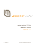
DESIGN A WIRELESS LAB FOR ECE4760
A Design Project Report
Presented to the School of Electrical and Computer Engineering of Cornell University
in Partial Fulfillment of the Requirements for the Degree of
Master of Engineering, Electrical and Computer Engineering
Submitted by
Yi Heng Lee
MEng Field Advisor: Bruce R. Land
Degree Date: May 2012
Abstract
Master of Engineering Program
School of Electrical and Computer Engineering
Cornell University
Design Project Report
Project Title: Design a wireless lab for ECE4760
Author: Yi Heng Lee
Abstract:
In this project, a wireless lab exercise is developed for the ECE4760 Digital
Systems Design using Microcontrollers course. The lab exercise involves the use
of Nordic systems nRF24L01+ transceivers for wireless communication between
Atmel ATmega644 microcontrollers. Device drivers compatible with the
ATmega644 were written for configuring and operating the nRF24L01+. Three lab
exercises of increasing complexity that demonstrate the usage of the transceivers
in different applications were developed.
1
Table of Contents
1. Executive Summary ..................................................................................................... 3
2. Design Requirements .................................................................................................. 4
3. Possible Solutions and Related work ......................................................................... 5
4. Design and Implementation ........................................................................................ 6
4.1. Hardware ................................................................................................................. 6
4.2. Device Drivers for the nRF24L01+ ......................................................................... 8
4.3. Lab Exercise 1: Receiving a Broadcast from the Base Station................................. 9
4.4. Lab Exercise 2: Sending an Audio Signal ...............................................................11
4.4. Lab Exercise 3: Wireless Multiplayer game ............................................................13
5. Results.........................................................................................................................16
5.1. Range of the Transceiver in the Philips Hall Digital Lab Environment .....................17
5.2. Throughput of the Transceiver when used with the ATmega644 ............................18
5.3. Evaluation of the Lab Exercises..............................................................................19
6. Conclusions ................................................................................................................20
7. Future Work.................................................................................................................20
8. Special Thanks ............................................................................................................20
9. Appendix .....................................................................................................................21
9.1. Schematics .............................................................................................................21
9.2. User Manual for nRF24L01+ Device Drivers ..........................................................22
9.2.1. List of files ..................................................................................................22
9.2.2. Description of Functions and Usage ...........................................................22
9.2.3. Examples ...................................................................................................23
2
1. Executive Summary
In this project, a wireless lab exercise is developed for the ECE4760 Digital
Systems Design using Microcontrollers course. The lab exercise involves the use
of Nordic systems nRF24L01+ transceivers for wireless communication between
Atmel ATmega644 microcontrollers. The exercises are designed such that several
groups of students connect to a base station, which is set up by the instructor or
teaching assistants. Since each nRF24L01+ can receive from up to 6 transmitters
when set up in a star network, each base station can support 6 groups of students.
Device drivers compatible with the ATmega644 were written for configuring and
operating the nRF24L01+. Three lab exercises of increasing complexity that
demonstrate the usage of the transceivers in different applications were developed.
The first exercise has students receive a message that is broadcast from the base
station. The second exercise has students transmit an audio signal to the base
station which plays the audio using speakers that are connected to it. The third
exercise is a wireless multiplayer game involving elastic particle collisions where
player control their character by sending commands to the base station. The base
station then passes the commands by serial interface to a Java program that runs
the game and displays its graphics.
The range and performance of the nRF24L01+ in the Philips Hall Digital Lab
environment was analyzed by measuring packet drop rates without the use of the
Enhanced Shockburst link layer for acknowledgements and retransmissions. The
range of the nRF24L01+ in the lab environment was found to be limited due to the
large amount of electronics and metal objects in the lab, which obstruct the RF
signals. The throughput that can be achieved when the nRF24L01+ is used with
the ATmega644 was also measured. It was found a significant overhead is
incurred in transmissions and thus using a large payload size (up to 32 bytes) for
each packet resulted in maximum throughput.
3
2.
Design Requirements
ECE 4760 is a senior level course offered by the Electrical and Computer
Engineering Department of Cornell University. In the course, students are taught to
use design real-time digital systems using microprocessor-based embedded
controllers. The course is taught by Bruce Land, who is also the advisor for this
project. The goal of this project is to develop a lab exercise for ECE 4760 involving
wireless communication between two microcontrollers. The course would benefit
from the addition of this lab exercise as it gives students experience with using
wireless transceivers and teaches them how to add wireless communication
capabilities to the electronic systems that they design. Even within the course,
students can build on what they have learnt in this lab to explore interesting
applications involving wireless communication in their final design project, where
students design and implement a microcontroller project of their choosing. Given
the rapid proliferation of wireless features in electronic devices, such knowledge
would be helpful in their future careers as electrical engineers.
The lab exercise will involve the use of 2.4 GHz transceivers for wireless
communication. Each transceiver will be connected to an Atmel Mega644
microcontroller on a STK500 development board or the prototype board designed
by Bruce Land and Nathan Chun. Based on the typical student enrollment in ECE
4760, each group of two students would have access to one STK500. Thus, the
exercise has to be designed such that several groups of students connect to a
base station, which is set up by the instructor or teaching assistants. Depending on
the number of students and the number of clients that each base station can
handle, multiple base stations might have to be used. The program running on the
base station would have to be designed to be fault tolerant and resilient to errors in
the data sent by the students, so that errors by a group would not hamper the use
of the base station by other groups.
4
The lab exercise has to be designed such that students can finish it in one or two
afternoons in a lab setting. Device drivers will have to be written and documented
to provide a hardware abstraction layer for the students to interface with the
transceivers. The drivers will be written in C and used as part of the programs that
students will implement and run on the Mega644 microcontrollers.
3.
Possible solutions and related work
The usage of the ATmega644 and nRF24L01+ for the hardware was specified as
per the design requirements. Another student at Cornell, Jaehyun Kim [3], had
previously written an API for the nRF24L01+ that was capable of basic point to
point communication between two transceivers. However, that API does not
support features such as multiceiver (receiving from multiple transceivers) in a star
network and using auto acknowledgements for reliable communication. The API
also has problems with switching between transmit and receive modes, requiring
the transceiver to be powered down when switching modes. There is also a
comprehensive set of drivers written by Brennan Ball of diyembedded.com [4] but it
is incompatible with the ATmega644 since they were written for the LPC2148 and
PIC18F452 microcontrollers.
I decided to write a new set of drivers based on the documentation by Brennan Ball
and reusing some of the code by Jaehyun Kim such as the mappings from register
names to addresses, macros for commands and some of the functions for setting
the TX and RX addresses. One of the main challenges with using the nRF24L01+
is the complexity involved in configuring and controlling it through multiple
commands sent by SPI, unlike simpler transceivers such as the Radiotronix WI.232
series which require minimal configuration. Thus in order to make it easier for
students to use the transceiver, I designed my drivers to be easy to use by
automatically doing many of the steps involved in setting up and operating the
5
transceiver. This does come at the expense of configurability since some of the
options are not exposed to the user through the API.
4.
Design and Implementation
4.1.
Hardware
The wireless transceiver to be used in the exercise is the Nordic Semiconductor
nRF24L01+. The transceiver operates in the worldwide ISM frequency band at
2.400 – 2.4835 GHz and support air data rates of 1 Mbps and 2 Mbps [2]. The
transceivers are controlled through a Serial Peripheral Interface (SPI) where
operations are performed by writing and reading registers in the nRF24L01+. The
project uses modules manufactured by Sparkfun Electronics which mount the
nRF24L01+, a 16 MHz crystal oscillator that produces the clock for the transceiver,
a chip antenna, and a 3.3V LDO regulator onto a 0.8x0.9” printed circuit board [5].
The module is connected to the ATmega644 as shown in Appendix 1. The module
is supplied with 5V through its VCC pin, which is then regulated to 3.3V for the
transceiver. The pins for the SPI interface are connected to ports B3 to B7 on the
Mega644, which are used by the integrated SPI interface of the ATmega644. The
nRF24L01+ supports a maximum SCK frequency of 4 MHz, thus the SPI frequency
of the ATmega644 is set to fosc/4 since a 16 MHz crystal is used for the
ATmega644.
I set the nRF24L01+ to use an RF data rate of 2 Mbps and the maximum RF
output power of 0 dBm, at which the transceiver is documented to draw 11.3 mA of
current when transmitting and 13.5 mA when receiving.
6
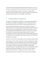
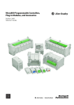
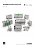
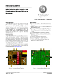
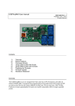
Figure 1: nRF24L01+ connected to the STK500, along with the trimpot used for the
wireless multiplayer game lab exercise.
7
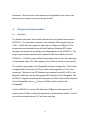
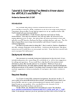
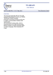
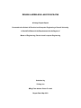
Figure 2: nRF24L01+ connected to the ATmega644 on the prototype board.
4.2.
Device Drivers for the nRF24L01+
Device drivers compatible with the ATmega644 were written for the nRF24L01+.
The drivers support point to point and multiceiver in a star network operation with
and without Enhanced Shockburst. Enhanced Shockburst is a link layer (like TCP)
built into the nRF24L01+ that supports auto acknowledgements and retransmission
of packets to achieve reliable communication at the expense of reduce throughput.
A receiver in multiceiver mode can receive transmissions from up to six
transmitters. This is done by enabling up to six data pipes and setting the RX
8
(receive) addresses for each pipe to correspond to the TX (transmit) address of
each transmitter.
The Enhanced Shockburst link layer also supports advanced features such as
dynamic payload length and piggybacking payloads on the auto
acknowledgements sent from the receiver to the transmitter. However, to keep the
drivers easy to use, I decided not to use these features and instead use static
packet sizes that are set by the user at initialization. The piggybacking payloads on
ACKs initially seemed to be an attractive way of sending replies containing data
from the base station to the student setups, however there is a hardware limitation
in the transceiver that limits the use of this feature. A payload can be included in an
ACK packet from the receiver to the transmitter. The TX FIFO (transmit first in first
out) which the payloads are stored in can only contain three pending payloads,
when ideally one would want capacity for six payloads, one for each pipe. Sharing
the three slots among six pipes presents problems such as slots in the TX FIFO
getting blocked if a transmitter stops communicating with the receiver while there is
a payload pending for the transmitter, resulting in the payload staying in the FIFO
indefinitely and preventing the use of the slot by other payloads. The user would
have to manually implement some mechanism to detect such occurrences and
flush the TX FIFO in order to share the three slots among six pipes.
4.3.
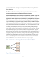
Lab Exercise 1: Receiving a Broadcast from the Base Station
Figure 3: Structure of lab exercise 1
9
The first exercise involves receiving packets which are broadcast from a base
station. This exercise can be used by students to check that they have connected
the transceiver correctly and the SPI communication to the transceiver is
functioning.
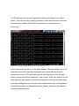
Figure 4: Console output of the received broadcast
All the transceivers are set to use the same address. The base station is set to TX
mode and continuously transmits characters from a string while the student
transceivers are set to RX mode and listen for the transmissions from the base
station, printing the received characters to the console. There only needs to be one
base station for any number of receivers as long as the receivers are within range.
Auto acknowledgements are not used for this exercise since they are designed for
transactions between one transmitter and one receiver, whereas in this exercise
we have multiple receivers.
10
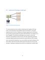
4.4.
Lab Exercise 2: Sending an Audio Signal
Figure 5: Structure of lab exercise 2
The second exercise involves students transmitting audio signals to the base
station, which plays them using speakers that are connected to it. The audio
signals are sent in the form of sequences of values ranging from 0 to 255, which
are converted to analog signals using pulse width modulation on the OC0A port of
the ATmega644. The exercise was designed as an extension to the Audio
Sequencer and Synthesizer lab exercise [6], with audio signal being generated
using direct digital synthesis with the code from that lab exercise. After students
have constructed the synthesizer, they can send their audio signal wirelessly to the
base station, which would combine all the signals received from various groups
and play it, resulting in interesting tunes based on combinations of student inputs.
11
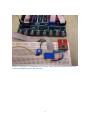
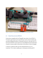
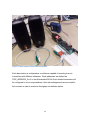
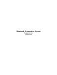
Figure 6: Base station connected to speakers
Each base station is configured as a multiciever capable of receiving from six
transmitters with different addresses. These addresses are defined as
PIPE_ADDRESS_0 to 6 in the Wirelesslab4760 file. Each student transceiver will
be configured to use a unique address. Auto acknowledgements are not used for
this exercise in order to maximize throughput on the base station.
12
4.5.
Lab Exercise 3: Wireless Multiplayer Game
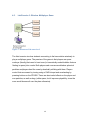
Figure 7: Structure of lab exercise 3
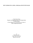
The third exercise involves students connecting to the base station wirelessly to
play a multiplayer game. The premise of the game is that players are space
cowboys (literally) that need to herd cows (in hermetically sealed bubbles that are
floating in space) into corrals. Both players and cows are modeled as spherical
particles and players herd the cows by elastically colliding with them. Players
control their movement by turning using a 10KΩ trimpot and accelerating by
pressing buttons on the STK500. There are also inertial effects on the player and
cow particles, as well as drag (unlike space, but it improves playability, since the
cows would bounce all over the place otherwise).
13
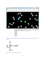
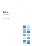
Figure 8: Screenshot of the game, the received player commands can be seen in the
console
Figure 9: Connections for the trimpot
14
The microcontroller on a student setup reads the value of the 10KΩ trimpot
(connected as shown above) using the analog to digital converter on the
ATmega644 and detects button presses on the STK500. SW0 and SW1 on the
STK500 are connected to Port C0 and C1 respectively on the ATmega644. The
program on the microcontroller encodes the information as a string, with the
student's NetID as the first 6 characters, 'F' or 'B' for the 7th character to indicate
forward or backwards acceleration, and a value from 0-255 corresponding to the
trimport reading for the last three characters. If the NetID or trimport reading are
shorter than 6 and 3 characters respectively, they are padded with spaces to keep
the string length consistent. Examples of strings are " yl478F 80" and
"abc123B150".
The strings are transmitted by the student setups to the base station. Similar to lab
exercise 2, there is one base station configured in multiciever mode for every six
student setups, and each student transceiver uses a unique address. The base
station sends the received strings to the computer using the serial connection,
adding the '<' and '>' brackets around the string so that the Java program can
detect the beginning and end of each string.
The game program is written in Java and runs on a computer connected to the
base station. This was done because of the ATmega644 does not have an
integrated VGA module, and manually generating an NTSC signal using software
in the microcontroller results in relatively low resolution black and white graphics.
The Java program reads the player commands from the serial connection, using
the jSSC (java simple serial sonnector) library by Sokolov Alexey [7]. The program
then performs the physics computations for the game and displays the state of the
game on the screen. The computations used to simulate the elastic collisions of
particles are based on the "Video Game -- Particle Beam" lab from the 2011
offering of ECE 4760, by Bruce Land [8].
15
The techniques learnt in this exercise can be applied to applications where
microcontrollers are deployed to collect information (such as sensors in the field)
and transmit back data wirelessly to a base station which uploads the data to a
computer for logging.
Originally, my plan for this exercise was to have two way communication between
the base station and the student setups, where the base station would reply with
the coordinates of the players and cows, and the students could write scripts or AI
programs to automatically play the game, or display the game on their own screens
by sending the coordinates to their computer by a serial connection. However, it
proved unfeasible to send the replies using the piggybacking payloads on ACKs
feature since the TX FIFO could only contain up to three packets as described
earlier. Having the base station switch to TX mode to transmit is slow and it would
miss packets that are sent to it by students while switching and transmitting. Two
way communication might be more feasible in a lab exercise that did not involve
real time game play, such as a turn based game.
5.
Results
In order to analyze the range of the nRF24L01+ and its throughput when used with
the ATmega644, one setup was set to transmit packets continuously while another
ran a program that receives those packets and records how many packets it
receives per second. The files used are located in the "Measure rate" directory of
the code submission. An interrupt service routine (ISR) is used to measure time in
the receiver. Every 10 seconds, the program takes the count of the packets it has
received in the last 10 seconds and prints the packets received per second to the
console.
16
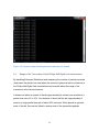
Figure 10: Console output showing measured packets per second
5.1.
Range of the Transceiver in the Philips Hall Digital Lab environment
By disabling Enhanced Shockburst and measuring the number of packets received
(and hence the packet loss rate) when the receiver is placed at various locations in
the Philips Hall Digital Lab, observations can be made about the range of the
transceiver in the lab environment.
A distance of about a quarter of the lab (approximately 4 meters) was resulted in a
packet loss rate of 5 to 10%. At a distance of about half the lab (approximately 8
meters), a large packet loss rate of about 30% occurred. When placed at opposite
ends of the lab, the receiver failed to receive most of the transmitted packets.
17
The limited range of the transceiver was possibly due to the large amount of
electronics and metal objects in the lab which obstruct the RF signals. Placing the
transceivers at a high altitude helped to reduce the packet loss rate.
5.2.
Throughput of the Transceiver when used with the ATmega644
The transmitter and receiver were placed half a meter from each other and the
throughput was measured with various payload sizes and settings for Enhanced
Shockburst. With a payload size of 1 byte and Enhanced Shockburst disabled, an
average of 4900 packets were received per second. When the payload was
increased to 4 bytes, 4580 packets were received per second. With the maximum
payload size of 32 bytes, an average of 2160 packets were received per second.
The less than proportional decrease in the rate at which packets are transmitted or
received as the payload size increases indicates that overhead comprises a
significant part of the delay involved in sending each packet. Based on the
nRF24L01+ documentation, one of the main contributors to the overhead could be
the TX settling delay of up to 130 µs that the transceiver goes through whenever it
switches from standby mode to TX mode (the transceiver is not supposed to be
kept in TX mode continuously, it automatically switches to standby mode once the
TX FIFO has been emptied).
Based on these results, using a large payload size is more efficient and results in a
higher throughput, since more data is transmitted per packet, while the rate at
which packets is not decreased by the same extent.
When Enhanced Shockburst is enabled, the number of packets per second
received with a 1 byte payload size fell from 4900 to 2933, yet surprisingly with a
32 byte payload size the cost of using Enhanced Shockburst was insignificant, with
the packets per second falling from 2160 to 2150.
18
5.3.
Evaluation of the Lab Exercises
The three lab exercises functioned as designed. However, testing could only be
done with one base station and up to four transmitters (simulating four players) for
the wireless game due to limited transceivers and manpower for setting them up.
The wireless game was playable when used with four transmitters that were
located on two adjacent workbenches. The scalability of the exercises to a lab
section of 20 students could not be tested due to insufficient transceivers and
manpower, it is possible the large number of transmissions occurring
simultaneously could interfere with each other. Using different frequencies for each
star network of 1 base station and up to 6 student setups might alleviate this
problem.
Based on the results from evaluating the throughput of the transceiver using
different payload sizes, lab exercise 2 could actually be improved significantly.
Instead of sending 1 byte packets which contain the real time value of the audio
waveform as is done currently, the transmitters should accumulate 32 byte
sequences of values which represent the audio waveform over 32 time steps,
which are then sent as 32 byte packets to the base station. The base station then
plays through the 32 bytes in each packet as time passes. This would result in
higher throughput and thus better audio quality (as it allows for a higher sample
rate) and scalability (as less packets need to be sent) compared to the current
implementation. Enhanced Shockburst can also be used with the 32 byte packet to
fix problems with packet losses disrupting the audio playback. In the current
implementation, packet losses sometime cause the audio to sound distorted.
19
6.
Conclusions
The project achieved its goal of developing ATmega644 compatible device drivers
for the nRF24L01+ and using them to build a lab exercise for ECE 4760. By
analyzing the performance of the nRF24L01+ in the Digital Lab environment when
used with the ATmega644, a better understanding of the capabilities and optimal
use of the nRF24L01+ was gained. However, due to equipment and manpower
shortages, testing for scalability could not be done with a greater number of
transceivers in order to simulate actual deployment of the lab exercises wherein
there may be up to 20 students groups simultaneously transmitting packets.
7.
Future Work
Future work could involve an improved version of lab exercise 2 which would have
the transmitters accumulate 32 byte sequences of values which represent the
audio waveform over 32 time steps and sent them as 32 byte packets to the base
station instead of current the audio waveform byte by byte in real time. This
modification would result in better efficiency and thus higher throughput, it would
also allow the use of Enhanced Shockburst to prevent audio distortions from
dropped packets.
8.
Special Thanks
I would like to thank Bruce Land for his advice and guidance on this MEng project,
and Jaehyun Kim for his prior work on the nRF24L01+, some of which this project
is based on.
20
7. Appendix
7.1. Schematics
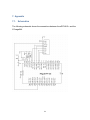
The following schematic shows the connections between the nRF24L01+ and the
ATmega644.
21
7.2. User Manual for nRF24L01+ Device Drivers
7.2.1. List of Files
The device drivers consists of four files.
wireless.h - Header file for the driver functions that are called by the user, as well
as helper functions
wireless.c - Driver functions that are called by the user, as well as helper functions.
Some of the functions are based on code by Jaehyun Kim.
cmd_list.h - Macros for commands that sent to the nRF24L01+ by SPI, written by
Jaehyun Kim. These are only used internally be drivers, the user does not need to
know them.
register_map.h - Mappings from register names to their addresses, written by
Jaehyun Kim. These are only used internally be drivers, the user does not need to
know them.
7.2.2. Description of Functions and Usage
Initializing and configuring the nRF24L01+
All the initialization can be done in the main method of the program.
The user first has to set the value of the payload length. This must be done before
calling any of the functions in wireless.c.
PAYLOAD_LENGTH = 1; //any number from 1 to 32
init_RF(unsigned char enhanced_shockburst_enable) is then called to configure
and power up the receiver. enhanced_shockburst_enable is set to 0 to disable
Enhanced Shockburst and 1 to enable it. The function also automatically
22
configures parameters such as the transmission power and data rate for the user,
in order to make the drivers easy to use.
init_RF(1); //init transceiver, enable enhanced shockburst
init_RF(0); //init transceiver, disable enhanced shockburst
The transceiver is initially configured to be in RX mode, to change modes the user
has to call set_mode(unsigned char mode), where mode is either RX_MODE or
TX_MODE.
By default, data pipes 0 and 1 are enabled, to enable additional pipes, the user can
call enable_pipe(unsigned char pipenumber) where pipenumber can be from 0 to 5.
enable_pipe(4); //enable data pipe 4
The RX and TX addresses have to be set by calling set_TX_addr(unsigned long
address) and set_RX_addr(unsigned long address, unsigned char pipe). In these
drivers, the transceiver is set to use 4 byte address, which correspond to an
unsigned long in the ATmega644. The RX address of each pipe is set seperately
by calling set_RX_address with different values for pipe from 0 to 5. For the
transmitter in TX_mode, the RX address for pipe 0 should be set to the same
address as the TX address in order for ACKs to be received. Based on the
nRF24L01+ documentation, it is recommended that addresses have multiple
transitions between 1 and 0 bits to avoid noise being mistaken for packets.
#define PIPE_ADDRESS_0 0xb4b5b600
#define PIPE_ADDRESS_4 0xb4b5b604
set_RX_addr(PIPE_ADDRESS_0, 0);
set_TX_addr(PIPE_ADDRESS_0);
set_RX_addr(PIPE_ADDRESS_4, 4);
23
set_RF_channel(unsigned char channel) can be used to change the RF channel,
transceivers must be set to the same channel to communicate with each other.
channel is a 7 bit number. Using different channels for different star networks can
help reduce interference.
set_RF_channel(8);
Sending and receiving packets
transmit_packet(char* packet) is called to transmit the packet which is a byte array
or string. It blocks until the packet is successfully transmitted (whereupon it returns
1) or the maximum number of retries is reached (whereupon it returns 2).
char transmission_result; //shows whether the transmission
succeeded
char* packet = (char *) malloc(PAYLOAD_LENGTH);
packet[0] = 'A';
transmission_result = transmit_packet(packet);
The program that is receiving packets should call RX_FIFO_status(void) to check
whether packets have been received, it returns 0 if no packets are in the RX FIFO
and 1 if packets are present. The transceiver automatically places packets in the
RX FIFO when they are received.
Once packets have been received, they can be read from the RX FIFO by calling
read_RX_payload(char* buffer).
char pipe_received; //pipe on which the packet was received
while (1) {
if (RX_FIFO_status() == 1) {
pipe_received = read_RX_payload(packet);
fprintf(stdout,"<%s>", packet);
24
}
}
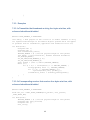
7.2.3. Examples
7.2.3.1a Transmitter that broadcasts a string four bytes at a time, with
enhanced shockburst disabled
#define PIPE_ADDRESS_0 0xb4b5b600
char data[] = "The purpose of this course is to enable students to carry
out sophisticated designs of the modern digital systems which now appear
in products such as automobiles, appliances and industrial tools.\n";
int main(void) {
unsigned char i;
unsigned char j;
char transmission_result;
PAYLOAD_LENGTH = 4; //set the payload length of each packet
init_RF(0); //init transceiver, disable enhanced shockburst
set_mode(TX_MODE);
set_RX_addr(PIPE_ADDRESS_0, 0);
set_TX_addr(PIPE_ADDRESS_0);
char* packet = (char *) malloc(PAYLOAD_LENGTH);
while (1) {
for (i = 0; i < strlen(data); i += PAYLOAD_LENGTH) {
strncpy(packet, data + i, PAYLOAD_LENGTH);
for (j = 0; j < PAYLOAD_LENGTH; j++)
fprintf(stdout,"%c", packet[j]);
transmission_result = transmit_packet(packet);
}
}
}
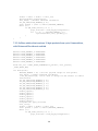
7.2.3.1b Corresponding receiver that receives four bytes at a time, with
enhanced shockburst disabled
#define PIPE_ADDRESS_0 0xb4b5b600
FILE uart_str = FDEV_SETUP_STREAM(uart_putchar, uart_getchar,
_FDEV_SETUP_RW);
int main(void) {
PAYLOAD_LENGTH = 4; //set the payload length of each packet
unsigned char pipe_received;
unsigned char j;
uart_init();
25
stdout = stdin = stderr = &uart_str;
fprintf(stdout,"starting\n");
init_RF(0); //disable enhanced shockburst
set_RX_addr(PIPE_ADDRESS_0, 0);
char* packet = (char *) malloc(PAYLOAD_LENGTH);
while (1) {
if (RX_FIFO_status() == 1) {
pipe_received = read_RX_payload(packet);
for (j = 0; j < PAYLOAD_LENGTH; j++)
fprintf(stdout,"%c", packet[j]);
}
}
}
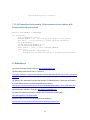
7.2.3.2a Base station that receives 10 byte packets from up to 6 transmitters,
with Enhanced Shockburst enabled
#define
#define
#define
#define
#define
#define
PIPE_ADDRESS_0
PIPE_ADDRESS_1
PIPE_ADDRESS_2
PIPE_ADDRESS_3
PIPE_ADDRESS_4
PIPE_ADDRESS_5
0xb4b5b600
0xb4b5b601
0xb4b5b602
0xb4b5b603
0xb4b5b604
0xb4b5b605
FILE uart_str = FDEV_SETUP_STREAM(uart_putchar, uart_getchar,
_FDEV_SETUP_RW);
int main(void) {
PAYLOAD_LENGTH = 10; //set the payload length of each packet
init_RF(1); //enable enhanced shockburst
//set_RF_channel(8); can be used to change the RF channel to reduce
interference
set_RX_addr(PIPE_ADDRESS_0, 0);
set_RX_addr(PIPE_ADDRESS_1, 1);
set_RX_addr(PIPE_ADDRESS_2, 2);
set_RX_addr(PIPE_ADDRESS_3, 3);
set_RX_addr(PIPE_ADDRESS_4, 4);
set_RX_addr(PIPE_ADDRESS_5, 5);
enable_pipe(0);
enable_pipe(1);
enable_pipe(2);
enable_pipe(3);
enable_pipe(4);
enable_pipe(5);
unsigned char pipe_received;
uart_init();
stdout = stdin = stderr = &uart_str;
char* packet = (char *) malloc(PAYLOAD_LENGTH);
while (1) {
if (RX_FIFO_status() == 1) {
pipe_received = read_RX_payload(packet);
26
fprintf(stdout,"<%s>", packet);
}
}
}
7.2.3.2b Transmitter that transmits 10 byte packets to base station, with
Enhanced Shockburst enabled
#define PIPE_ADDRESS_2 0xb4b5b602
int main(void) {
char transmission_result;
PAYLOAD_LENGTH = 10; //set the payload length of each packet
init_RF(1); //init transceiver, enable enhanced shockburst
set_mode(TX_MODE);
set_RX_addr(PIPE_ADDRESS_0, 0);
set_TX_addr(PIPE_ADDRESS_0);
char* packet = (char *) malloc(PAYLOAD_LENGTH);
while (1) {
sprintf(packet, "abcdefghij");
unsigned char transmission_result = transmit_packet(packet);
}
}
8. References
[1] Cornell University Courses of Study, http://courses.cornell.edu/
[2] Nordic Semiconductor nRF24L01+ datasheet,
http://www.nordicsemi.com/kor/content/download/2726/34069/file/nRF24L01P_Product_Specificatio
n_1_0.pdf
[3] Jaehyun Kim, Application Programming Interface For Radiofrequency Transceiver nRF24L01+,
by Nordic Semiconductor and Atmel Mega644 microcontroller
http://people.ece.cornell.edu/land/courses/ece4760/StudentWork/Jaehyun_Kim_jk726/index.html
[4] Brennan Ball, nRF24L01 Tutorials. http://blog.diyembedded.com/
[5] SparkfunTransceiver nRF24L01+ Module with Chip Antenna product page,
http://www.sparkfun.com/products/691
[6] Bruce Land, ECE 4760: Sound sequencer and synthesis.
http://people.ece.cornell.edu/land/courses/ece4760/labs/s2012/lab3.html
27
[7] Sokolov Alexey, jSSC (java simple serial connector) https://code.google.com/p/java-simpleserial-connector/
[8] Bruce Land, ECE 4760: Laboratory 3 Video Game -- Particle Beam.
http://people.ece.cornell.edu/land/courses/ece4760/labs/s2011/lab3.html
28