1
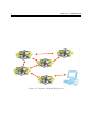
Wireless Communication Systems
in a Swarm of Autonomous
Flying Helicopters
eingereichte
STUDIENARBEIT
von
Ludwig John
geb. am 21.08.1986
B.Sc. Alexandra Marinescu
geb. am 28.08.1989
wohnhaft in:
Billrothstr. 18
81369 München
Tel.: 089 51665558
wohnhaft in:
Kreuzhofstr. 6
81476 München
Tel.: 0176 83260686
Lehrstuhl für
STEUERUNGS- und REGELUNGSTECHNIK
Technische Universität München
Univ.-Prof. Dr.-Ing./Univ. Tokio Martin Buss
Univ.-Prof. Dr.-Ing. Sandra Hirche
Betreuer:
Beginn:
Zwischenbericht:
Abgabe:
Prof. Dr. sc.nat. Jörg Conradt & M.Sc. Cristian Axenie
07.11.2011
12.12.2011
20.01.2012
Abstract
The ability to communicate and collaborate is essential for any multi-agent tasks.
WLAN is a simple possibility to integrate such communication into existing networks. Since the various commercial modules for mobile robots are typically expensive, operate on relatively low transmission speed and also don’t have robot(agent)
specific dimensions, the aim of this project is to design and implement a task specific
communication protocol aimed at offering point to point communication in networks
with constantly and rapidly changing topologies.
Zusammenfassung
In der Lage zu sein, zu kommunizieren und zusammen zu arbeiten ist essenziell
für jedes Multiagenten System. WLAN ist die einfachste Lösung, um Kommunikationmöglichkeiten in ein existierendes Netzwerk zu integrieren. Da die verschieden kommerziel verfügbaren Module für mobile Roboter sehr teuer sind, und
relativ lange Übertragungszeiten haben und zusätzlich nicht die Roboter spezifischen Abmessungen haben, ist das Ziel dieses Projekts, das Design und die Implementierung eines Aufgaben spezifischen Kommunikationsprotokolls, welches dafür
ausgelegt sein soll, Punkt zu Punkt Kommunikation in einem Netzwerk mit sich
andauernd und schnell wandelnder Topologie zu ermöglichen.
2
3
CONTENTS
Contents
1 Introduction
5
2 Hardware
2.1 Transceiver (nRF24L01+) . . . . . .
2.1.1 Radio Control . . . . . . . .
2.1.2 Enhanced ShockBurst™ . . .
2.1.3 Data and Control Interface .
2.2 LPC2103 Education Board . . . . . .
2.2.1 Expansion Connector . . . .
2.2.2 UART Port . . . . . . . . .
.
.
.
.
.
.
.
.
.
.
.
.
.
.
.
.
.
.
.
.
.
.
.
.
.
.
.
.
.
.
.
.
.
.
.
.
.
.
.
.
.
.
.
.
.
.
.
.
.
.
.
.
.
.
.
.
.
.
.
.
.
.
.
.
.
.
.
.
.
.
.
.
.
.
.
.
.
.
.
.
.
.
.
.
.
.
.
.
.
.
.
.
.
.
.
.
.
.
.
.
.
.
.
.
.
.
.
.
.
.
.
.
.
.
.
.
.
.
.
.
.
.
.
.
.
.
3 Intoduction to MANET and Communication Protocols
3.1 Mobile Ad Hoc Networks . . . . . . . . . . . . . . . . . . . . . . . .
3.2 MANET Protocol . . . . . . . . . . . . . . . . . . . . . . . . . . . .
3.3 Taxonomy of MANETs [JG07] . . . . . . . . . . . . . . . . . . . .
3.3.1 Proactive routing protocols . . . . . . . . . . . . . . . . . .
3.3.2 Reactive on-demand routing protocols . . . . . . . . . . . .
3.4 Protocol Choice . . . . . . . . . . . . . . . . . . . . . . . . . . . . .
3.4.1 Design Challenges . . . . . . . . . . . . . . . . . . . . . . . .
3.4.2 Comparison of the Proactive and Reactive Routing Protocols
4 Protocol
4.1 Message Types . . . . . . . .
4.2 Neighbour Search . . . . . .
4.3 Route Request . . . . . . . .
4.4 Message Handling . . . . . . .
4.4.1 Packet History . . . .
4.4.2 Message Transmission
.
.
.
.
.
.
.
.
.
.
.
.
.
.
.
.
.
.
.
.
.
.
.
.
.
.
.
.
.
.
.
.
.
.
.
.
.
.
.
.
.
.
.
.
.
.
.
.
.
.
.
.
.
.
.
.
.
.
.
.
.
.
.
.
.
.
.
.
.
.
.
.
.
.
.
.
.
.
.
.
.
.
.
.
.
.
.
.
.
.
.
.
.
.
.
.
.
.
.
.
.
.
.
.
.
.
.
.
.
.
.
.
.
.
.
.
.
.
.
.
.
.
.
.
.
.
.
.
.
.
.
.
.
7
7
7
9
11
15
15
15
.
.
.
.
.
.
.
.
17
17
19
19
21
21
21
21
22
.
.
.
.
.
.
23
23
24
24
26
26
26
5 Conclusions and Outlook
31
A Content of the CD-ROM
33
List of Figures
35
4
CONTENTS
List of Tables
37
Bibliography
39
5
Chapter 1
Introduction
In a disaster recovery environment, for example, with no preexisting communication
infrastructure, the actual conditions do not allow humans to examine the disaster
area on their own as it might put their lives in danger. Instead, a swarm of flying helicopters (agents) as depicted in Figure (1.1) can be used for the recognition mission.
Without a proper communication between them, the agents will not be able to organize themselves into a swarm or to optimize the accomplishment of the task, making
the mission goals difficult to achieve.
Establishing communication between the individual units is therefore essential, not
only for this particular case, but for the collective tasks in general. The aim of this
project is to develop a tiny printed-circuit-board (PCB), consisting of a transceiver
chip and a microcontroller, aimed at representing a complete stand-alone communication system.
In the first part of this report the main hardware components of such an elementary
chip will be introduced. Then an evaluation of different communication schemes for
a possibly large number of mobile nodes in a network with dynamically changing
topology will be performed. Finally, an appropriate communication protocol will be
chosen, followed by an overview of its actual implementation and functionality.
6
Wireless Communication Sy
Swarm of Autonomous Flying
CHAPTER 1. INTRODUCTION
! develop a tiny printed-circuit-board (PCB)
" ARM microcontroller (Cortex M3, e.g. LPC1769)
" wireless communication module (SPI interface)
! develop software for point-point communication
! develop software for network communication
Figure 1.1: Swarm of Flying Helicopters.
http://www.nst.ei.tum.de
7
Chapter 2
Hardware
In this chapter, the main hardware components of an elementary unit will be introduced. As a test environment for the MANET protocol, several nodes will be
communicating with each other over radio frequency (RF). Each of these units consist of a transceiver, as described in Section (2.1) and a microcontroller board, as
described in Section (2.2).
2.1
Transceiver (nRF24L01+)
The transceiver used in this project is the nRF24L01+ single chip transceiver from
Nordic Semiconductor. It uses the 2.4 GHz ISM (Industrial, Scientific and Medical)
band. All frequency bands that can be used for high frequency devices in Industrial-,
Scientific- or Medical applications are called ISM bands. Furthermore the transceiver
can transmit with on air data rates up to 2 Mbps and has a build-in protocol called
Enhanced ShockBurst. The transceiver is designed for ultra low power operation
[NS08].
2.1.1
Radio Control
This section describes the radio control options and the operational modes of the
nRF24L01+ radio transceiver.
Operational Modes
The nRF24l01+ can run in different operational modes. There are the two active
modes, the TX mode for transmitting packets and the RX mode for receiving packets. In addition to that, there are three passive modes for power saving. The power
down mode has the lowest power consumption. In this mode only the register values
are maintained and the SPI is kept active. In standby I mode the crystal oscillator
is partly active, which consumes more current, but allows faster switching to one of
the active modes. The last passive mode is standby II. Here, the nRF24L01+ waits
8
CHAPTER 2. HARDWARE
for packets uploaded to the TX FIFO register. As soon as a new packet arrives, the
packet can be send without the 130µs delay for the Phase-locked loop (PLL) settling. The interaction between these states is shown in the state diagram in Figure
(2.1) [NS08].
Figure 2.1: Radio control state diagram [NS08].
Air Data Rate
The nrf24L01+ supports different air data rates: 250kbps, 1Mbps or 2Mbps. On one
hand, a lower air data rate gives a better receiver sensitivity than higher air data
9
2.1. TRANSCEIVER (NRF24L01+)
rates. On the other hand though, a high air data rate gives lower average current
consumption and reduced probability of on-air collisions [NS08].
RF Channel Frequency
The channel frequency can be set in a range from 2.4GHz to 2.525GHz in steps of
1MHz. To set up the channels for 2Mbps data transfer rate, the channel spacing
between two channels should be at least 2MHz.
The transmitter and the receiver must use the same channel frequency in order for
them to be able to exchange packets [NS08].
Power Amplifier
In order to save current, the power amplifiers amplification for transmission can be
set up in four different steps. Table (2.1) shows the output power according to the
current consumption [NS08].
RF output power
0dBm
-6dBm
-12dBm
-18dBm
DC current
consumption
11.3mA
9.0mA
7.5mA
7.0mA
Table 2.1: RF output power setting for the nRF24L01+ [NS08].
2.1.2
Enhanced ShockBurst™
The nrf24l01+ transceiver has a build-in protocol called Enhanced ShockBurst™.
Enhanced ShockBurst™ is a packet based data link layer that features automatic
packet assembly and timing, automatic acknowledgement and retransmissions of
packets [NS08].
The build-in protocol allows to easily set up a connection between two transceivers
and reduces the load on the microcontroller, since all protocol operation are performed on the transceiver.
Packet Format
Figure (2.2) shows the structure of an Enhanced ShockBurst™ packet:
• Preamble
The preamble is a one byte long alternating sequence of ’1’ and ’0’ aimed at
synchronizing the receivers demodulator to the incoming bit stream.
10
CHAPTER 2. HARDWARE
• Address
The address ist used to logically distinguish between the different pipelines
in the same RF channel. According to the needs of the application the
address can have a length of three, four or five bytes.
• Packet Control Field
The packet control field, as showed in Figure (2.3), contains control information for the packet. The payload length information is mandatory to
allow dynamic payload length. The PID is used to detect packets that
were retransmitted because the acknowledgement was lost. The NO ACK
flag allowes to disable the acknowledgement for certain packets.
• Payload
The payload is the user defined content of the packet. It can also have a
variable length, which can be dynamically changed.
• CRC
The CRC is the mandatory error detection mechanism in the packet. It is
either 1 or 2 bytes and is calculated over the address, Packet Control
Field and Payload.
Figure 2.2: Enhanced ShockBurst™ packet format [NS08].
Figure 2.3: Control field [NS08].
2.1. TRANSCEIVER (NRF24L01+)
11
PTX Operation
Figure (2.4) shows the flowchart of the PTX operation of a nrf24l01+ starting form
Standby-I mode. If CE is set to ’1’, the transceiver changes to active mode and starts
transmitting the payload stored in the TX FIFO. If no data is present in the TX
FIFO the transceiver waits in Standby-I mode as long as CE is set to ’1’. The payload
from the TX FIFO is assembled to a packet and transmitted. If the auto retransmit
feature is enabled and the NO ACK flag is set to ’0’, the transceiver changes to RX
mode to wait for the acknowledgement. If no acknowledgement is received after the
maximum number of retransmits the MAX RT IRQ is set and the transceiver changes
to Standby-I mode. In case of a successful received acknowledgement the TX DS IRQ
is set.
PRX Operation
The flowchart in Figure (2.5) shows the PRX behavior after entering Standby-I mode.
Packets can only be received, if the transceiver is in active mode, by setting CE to ’1’.
If the auto acknowledgement feature is disabled, packets are stored to RX FIFO as
long as the latter is not full. If the auto acknowledgement feature is enabled, it first
has to be checked whether a packet is new or retransmitted. Only new packages
are being added to the RX FIFO. If the acknowledgement packet has a payload
attached to it, the latter is stored in the TX FIFO and the TX DS IRQ is set. If the
packet requires sending back an acknowledgement, the transceiver switches to TX
mode long enough to send the ACK packet and returns immediately to RX mode
afterwards.
MultiCeiver™
MultiCeiver™ is a feature that allows the nrf24l01+ to decode packets in RX mode
for six parallel data pipes with unique addresses. A data pipe is a logical channel in
the physical RF channel. The data pipes can be configured for individual behaviour.
2.1.3
Data and Control Interface
The nrf24l01+ transceiver is accessible via Serial Peripheral Interface (SPI). SPI
devices communicate in master/slave mode. For this application the microcontroller operates as master and can therefore initiate the communication, while the
transceiver operates as slave.
Figures (2.6) and (2.7) show a typical read and write operation between microcontroller and transceiver.
The CSN signal is set to ’0’ to initiate the data frame. The SPI communication
runs in full duplex mode over two different connections: the MISO (Master Input
Slave Output) connection and the MOSI (Master Output Slave Input) connection.
12
CHAPTER 2. HARDWARE
Figure 2.4: PTX operations in Enhanced ShockBurst™[NS08].
2.1. TRANSCEIVER (NRF24L01+)
Figure 2.5: PRX operations in Enhanced ShockBurst™[NS08].
13
14
CHAPTER 2. HARDWARE
Figure 2.6: SPI read operation [NS08].
There is always one byte transmitted in both directions. The transmission clock SCK
is defined by the master device. Every read and write command for the different
registers of the transceiver is encoded with a unique command word. This is the first
byte send by the microcontroller and defines the operation. In the signal diagrams,
the command bits are labelled with a Cn. For this byte, the transceivers sends
the current content of the status register labelled with Sn. After that, the actual
data, marked with Dn, is also sent. In contradiction to the bits which are ordered
from MSBit (Most Significant Bit) to LSBit (Leased Significant Bit), the bytes are
ordered from LSByte to MSByte.
Figure 2.7: SPI write operation [NS08].
15
2.2. LPC2103 EDUCATION BOARD
IRQ Pin and CE Pin
There are two additional pins to control the transceiver:
• the CE pin to switch between active and passive mode,
• the IRQ pin which can show the TX DS IRQ (send successful interrupt), RX DR
IRQ (packet received interrupt) or MAX RT IRQ (maximum number of retransmits interrupt).
2.2
LPC2103 Education Board
The LPC2103 Education Board is the hardware basis of the network nodes. The
board is build around a microcontroller based on the ARM7TDMI chip architecture.
It has 32KBytes program Flash and 8KBytes SRAM [EA12].
2.2.1
Expansion Connector
The 20 pos expansion connector is used to connect the transceiver with the microcontroller. Table 2.2 shows the relation between the microcontroller pins, the pins
of the connector and the external pins of the transceiver [EA12].
LPC2103
GND
P0.15 (EINT2)
P0.5 (MISO0)
P0.6 (MOSI0)
P0.4 (SCK0)
P0.7 (SSEL0)
P0.9 (GPIO)
VDD
Connector
pin 20
pin 14
pin 4
pin 5
pin 3
pin 6
pin 8
pin 19
nrf24l01+
GND
IRQ
MISO
MOSI
SCK
CSN
CE
VCC
Table 2.2: The connection between LPC2103 and nrf24l01+ [EA12, NXP09].
The communication between microcontroller and transceiver is described in Section
(2.1.3).
2.2.2
UART Port
UART0 on the LPC2103 is connected to a USB-to-serial bridge chip (FT232RL
from FTDI). The serial interface is not a full interface, only the receive and transmit signals are connected to UART0. This allows to connect the microcontroller to
a computer to program the microcontroller and print messages from the microcontroller on a terminal [EA12].
16
CHAPTER 2. HARDWARE
17
Chapter 3
Intoduction to MANET and
Communication Protocols
Kleinrock [Kle03] describes ad hoc networking technology in one of his papers as
”a blend of nomadicity, embeddedness, and ubiquity. In a network of the future,
users and computing devices will be able to connect to such a network conveniently
and even transparently. Computing and communication capabilities will not only
be restricted to standard electronic devices, but every gadget can afford to embed
a considerable amount of intelligence. On a global basis, devices in the network
will be able to rely on other devices to relay packets for them if necessary” [CLL].
This way, the world will be heterogeneously networked by a vast ”invisible global
infrastructure” [Kle03], considers Kleinrock.
Since the mentioned mobile ad hoc networks (MANETs) have become increasingly
popular over the last few years, this chapter starts by giving a quick overview on
their structure and main characteristics. After understanding the core concept of
the MANETs, the different possible topologies of such networks will be introduced,
together with the common design constraints, which have to be considered when
building such a structure.
3.1
Mobile Ad Hoc Networks
A mobile ad hoc network is a wireless mobile network formed spontaneously without
the aid of centralized administration or standard support services regularly available
as on conventional networks. Communication in such a decentralised network typically involves temporary multi-hop relays, with the nodes using each other as the
relay routers without any fixed infrastructure. They are allowed to move randomly
and organize themselves arbitrarily; the network’s topology might therefore change
rapidly and unpredictably (Figure 3.1) [JG07].
18
CHAPTER 3. INTODUCTION TO MANET AND COMMUNICATION PROTOCOLS
Figure 3.1: MANET Topolgy with One Possible Route.
3.2. MANET PROTOCOL
3.2
19
MANET Protocol
To facilitate communication within the network a routing protocol is to be implemented in order to discover the routes between nodes and therefore be able to send
messages. The goal of the routing protocol is to have an efficient route establishment between a pair of nodes, so that messages can be delivered in a timely manner.
Also, the well known routing protocols used in wired networks cannot be used for
mobile ad hoc networks since they are not considering the main property of ad hoc
networks: node mobility.
3.3
Taxonomy of MANETs [JG07]
In order to classify and evaluate the different MANET protocols, several criteria
reflecting fundamental design and implementation choices have to be considered.
Communication Model
• Multi-channel communiation
Multi-channel protocols are low level routing protocols which combine channel assignment and routing functionality.
• Single-channel communiation
Single-channel protocols relay on specific link layer behaviours and are Carrier
Sense Multiple Access/Collision Avoidance (CSMA/CA) oriented.
Structure
• Uniform protocols
None of the nodes takes a distinguishing role in the routing scheme. There
is no hierarchical structure in the network.
• Non-uniform protocols
Routing complexity is being limited by reducing the number of nodes participating in the routing computation.
20
CHAPTER 3. INTODUCTION TO MANET AND COMMUNICATION PROTOCOLS
State Information
• Topology based protocols
The topology based protocols rely on link state protocols. The participating nodes maintain large-scale topology information. Each node makes
decisions based on complete topology information.
• Destination based protocols
Each node maintains a distance and vector (next hop) to the destination node.
Each node exchanges its distance estimates for all other network nodes
with each of its immediate neighbors. Such algorithms behave poorly
leading to routing loops and slow convergence in a dynamic environment.
Type of Cast Property
• Unicast
Unicast forwarding refers to a one-to-one communication: the sender transmits data packets to a single destination.
• Geocast
The data packets are delivered to all the nodes situated in a specified geographical area. Geocasting can therefore be also seen as a form of
”restricted” broadcasting.
• Multicast
The sender transmits a message to multiple destinations.
• Broadcast
Each sent message is received by all the nodes located in the transmission
range of the sender (a distance from one hop).
Sheduling
• Proactive routing protocols
• Reactive on-demand routing protocols
3.4. PROTOCOL CHOICE
3.3.1
21
Proactive routing protocols
Proactive routing protocols are table-driven: they attempt to maintain consistent,
up-to-date routing information between every pair of nodes in the network by proactively propagating route updates at fixed time intervals [409]. In order to store the
routing information, each node maintains a so-called ”routing table”.
Each of the nodes responds to changes in the network topology by propagating
updates throughout the MANET in order to maintain a consistent network view
[RT99].
3.3.2
Reactive on-demand routing protocols
The source-initiated on-demand routing generates routes only when and if the source
node requests it. When the latter tries sending a package to a destination node,
which either has no entry in the routing table of the source node (node unknown) or
has a route attached which now is unavailable, it initiates a route discovery process
within the network.
This process is completed once a route is found or all possible route permutations
have been examined. Once a route has been established, it is maintained in the
corresponding routing tables along the path until the destination is no longer accessible, or the route expires.
3.4
Protocol Choice
In order to find the type of protocol that best fits our task description and to motivate our final choice, the general design challenges are first to be considered, followed
by a comparison of the reactive and proactive protocols.
3.4.1
Design Challenges
Probably the biggest design challenge in designing a MANET protocol is the lack of
infrastructure. The network does not depend on any established structure so each
node acts as an independent router. The constant and unpredictable changing of
the network topology results in routes becoming unavailable quite frequently and
packets being lost.
Also, as already mentioned, since no default router is available, every single node
in the network will act as a router; it will forward all incoming packets which will
22
CHAPTER 3. INTODUCTION TO MANET AND COMMUNICATION PROTOCOLS
most probably lead to the network being swamped with data packets.
Last but not least, each of the mobile nodes must be carrying batteries onboard, in
order to supply themselves with power. But since the power supply is limited, the
processing power will also be limited, which will further limit the services and the
application supported by the nodes.
3.4.2
Comparison of the Proactive and Reactive Routing
Protocols
In this section the reactive and proactive protocols are to be compared by considering the design challenges presented in the previous section.
First of all, on-demand reactive protocols are generally more efficient than proactive
ones. As depicted in Table (3.1), on-demand protocols minimize power consumption since routes are only established when required. Proactive protocols require
periodic route updates to keep information current and consistent which leads to a
worse performance. They also maintain multiple routes that might never be needed,
adding unnecessary routing overheads.
Second of all, proactive routing protocols provide better quality of service than ondemand protocols, since in the former case the available routes are constantly being
updated and therefore kept up-to-date. This minimizes, at the same time, the endto-end delay.
Last but not least, if we consider the throughput, we notice that proactive protocols
perform better than reactive protocols. [JG07]
Feature
Routing Load
Power consumption
End-to-End Delay
Throughput
Proactive protocol
−
−
+
+
Reactive Protocol
+
+
−
−
Table 3.1: Comparison of the Proactive and Reactive Routing Protocols.
By keeping in mind both the aim of the project and the hardware constraints,
we evaluated the existing communication protocols and settled for the reactive ondemand version, which we will discuss in detail in the next chapter.
23
Chapter 4
Protocol
This chapter will give an overview of both the implementation of the chosen MANET
protocol and its functionality.
As already mentioned in the previous chapter, we settled for a reactive on-demand
protocol since we are dealing with low MCU memory (SRAM).
Again, the source-initiated on-demand routing generates routes only when and if
the source node requests it. When the latter tries sending a package to a destination node, which either has no entry in the routing table of the source node (node
unknown) or has a route attached which now is unavailable, it initiates a route discovery process within the network.
The available routes to a specific destination are all saved to the corresponding entry
of the implemented routing table.
4.1
Message Types
The implemented communication system handles three different types of messages:
• Neighbour Search,
• Route Request,
• Message Handling.
In order to distinguish between the different types, a so-called message ID has been
introduced as the first byte of every message. This way, the communication system
can process the incoming message in an appropiate way, depending on the ”label”,
that was assigned.
24
CHAPTER 4. PROTOCOL
4.2
Neighbour Search
The biggest challenge in designing a MANET protocol is probably the constant and
unpredictable changing of the network topology. Recognizing and being able to
communicate immediately with the neighbours in transmission range of one node
(one-hop distance) is therefore essential for a working communication system.
As depicted in Figure (4.1), the individual nodes broadcast in short intervals with a
predefined length a ”Hello” message in their close proximity. The ”Hello” message
has the following structure:
• first byte: message ID (HELLO),
• second byte: node ID of the source.
In responde to the received ”Hello” message, the nodes in the transmission range
of the source node send back to the address in the second byte a ”Hello Reply”
message, which has the following structure:
• first byte: message ID (HELLOREP),
• second byte: node ID of the source.
After decoding the message ID, the source node updates the entries of its routing
table by adding a direct route to the neighbours whose addresses are consistent with
the second byte of the received ”Hello Reply”.
4.3
Route Request
To get informations about routes beyond the direct neighbours, a route exploration
has to be initiated. For this purpose the node looking for a route starts a route request by broadcasting a ”RREQ” message. This ”RREQ” message has the following
structure:
• first byte: message ID (RREQ)
• second byte: target node
• third byte: node ID
• following bytes: Node IDs of all nodes that have been passed forming a route
Vector.
If a route request reaches a node, it is checked whether the node is already include
in the ”RREQ” message. If so, the message is discarded, which ensures that the
”RREQ” message won’t get stuck in a routing loop. If not, the node ID is added
to ”RREQ” message and the message is broadcasted again. At some point one
25
4.3. ROUTE REQUEST
Figure 4.1: ”Hello” Message.
26
CHAPTER 4. PROTOCOL
or multiple versions of this ”RREQ” message will reach the target node. There,
the routes are stored in the routing table. The route replay message is built and
sent back along the route the related route request message took. These ”RREP”
messages have the following structure:
• first byte: message ID (RREP)
• following bytes: node IDs in order of the route from the requesting node to
the target node
On the way back to the RREQ source, every node safes the route in both directions
in his own routing table. Every node along the route will therefore know in which
direction he has to forward a message along the route. Since the ”RREQ” message
is broadcast through the hole network it is highly likely that the request will lead
to multiple results. The additional routes are not discarded; they are also saved in
the corresponding routing table so that, in the case that the preferred route breaks,
they can be used to safe the time and bandwidth it would take for a new request
(Figure (4.3)).
4.4
Message Handling
In the previous part we described the packets that are needed to maintain the
network structure. The following section deals with the actual user specified message
that is going to be fed as an input to the network.
4.4.1
Packet History
In order to keep track of the already sent messages, that are still waiting for a route
or an acknowledgement packet, the node stores the former in a so-called ”packet
history”. The packets are stored until the successful transmission is confirmed or it
ultimately fails. This is the case when no route is found or the maximum number
of retransmits is reached.
4.4.2
Message Transmission
Messages are transmitted within the payload of the ”MSG” packet. This packet has
the following structure:
• first byte: message ID (MSG)
• second byte: ID of the source node.
• third byte: ID of the target node.
• fourth byte: ID of this packet.
4.4. MESSAGE HANDLING
Figure 4.2: Route Request and Route Reply Functions.
27
28
CHAPTER 4. PROTOCOL
Figure 4.3: Route Request and Route Reply Functions with Fallback Routes.
4.4. MESSAGE HANDLING
29
• fifth byte: Lifetime of this packet.
• following bytes: payload of the packet
The message packet is send along a route from node to node. If it reaches the target
node, an acknowledgement message is generated and send back to the source node.
This ”ACK” message looks as follows:
• first byte: message ID (ACK)
• second byte: ID of the source node.
• third byte: ID of the target node.
• fourth byte: ID of this packet that should be acknowledged.
• fifth byte: Lifetime of this packet.
If at any point of the route the message can’t be forwarded, a negative acknowledgement is generated and sent back to the source node of the data packet. This
”NOACK” message looks as follows:
• first byte: message ID (NOACK)
• second byte: ID of the source node.
• third byte: ID of the target node.
• fourth byte: ID of this packet that should be acknowledged.
• fifth byte: Lifetime of this packet.
In the case of the ”MSG”, ”ACK” or ”NOACK” packets, it can happen that, due to
routing errors, they are send in circles. In order to avoid this, the number of hops
are counted and stored in the fifth byte. If the number exceed a certain predefined
amount of hops, the packets are deleted.
30
CHAPTER 4. PROTOCOL
Figure 4.4: Message Send Function.
31
Chapter 5
Conclusions and Outlook
In this chapter a quick review is given as to how well the results of this project cover
the tasks described in the problem formulation and an outlook is presented on what
can be done to further improve the existing communication system.
We managed to implement a MANET protocol which suits both the task description and the existing hardware constraints. The latter resulted though in strong
limitations of the payload length, the routing table or even the number of saved
fallback routines. As a further improvemet we would therefore suggest the use of
a microcontroller (MCU) that disposes of a bigger SRAM memory. The LPC21XX
family offers a broad variety of MCUs, so the code could easily be adapted with only
a few or even no changes at all.
In the short time of this practical course we were able not only to design and implement a tailor-made MANET protocol, but also to verify its basic functionality by
implementing a demo application. Since this takes place on the data layer, we also
suggest the development of an application layer aimed at allowing and promoting
the external use of the implemented protocol.
We also consider the security of the network of great importance, since the former
is one of the main design challenges in building communicating and collaborating
systens. For the use of the proposed communication system in a real environment
and under normal working conditions, security issues should be considered. Since
wireless networks are very vulnerable to attacks, part of a future work should be to
encrypt the messages handled by the network.
32
CHAPTER 5. CONCLUSIONS AND OUTLOOK
33
Appendix A
Content of the CD-ROM
/edulpc2103/examples/examples.zip Zip-file with all example codes from the
Embedded Artists website.
/edulpc2103/ide/lpc21isp 183.tar.gz Source code of lpc21isp. lpc21isp is a
portable command line ISP for Philips LPC2000 family and Analog Devices
ADUC70xx.
/edulpc2103/ide/linux/gnu.chain.for.armelf.tar.bz2 64bit linux precompiled
GNU Toolchain for arm-elf cross compiling.
/edulpc2103/ide/win/LPC2xxx-gcc-newlib-v2 4 0 1.exe IDE for Windows
XP requires GNU Toolchain.
/edulpc2103/ide/win/bu-2.18 gcc-4.2.2-c-c++ nl-1.15.0 gi-6.7.1.exe GNU
Toolchain for arm-elf cross compiling for windows needed for the IDE.
/edulpc2103/manuals/data.sheet.lpc2103.pdf Data sheet for the LPC2103 microcontroller.
/edulpc2103/manuals/edu lpc2103 baseboardSchematic v1 1.pdf board schematics of the LPC2103 Education Board.
/edulpc2103/manuals/LPC2103 Education Board Users Guide.pdf User guide
for the LPC2103 Education Board.
/edulpc2103/manuals/manual.arm7tdmi-s.pdf Reference manual for the ARM7tdmis architecture.
/edulpc2103/manuals/QuickStart Guide-Version 1.1.pdf QuickStart Program
Development User’s Guide for the LPC2103 Education Board.
/edulpc2103/manuals/user.manual.lpc2103.pdf User manual of the LPC2103
microcontroller.
34
APPENDIX A. CONTENT OF THE CD-ROM
/edulpc2103/rtos/RTOS LPC2xxx v2.2.zip Realtime operating system from
Embedded Artists
/nrf24l01/manual/data.sheet.nRF24L01P.pdf Data sheet for the nrf24l01+
transceiver.
/nrf24l01/tutorials/nrf24l01 tutorial 0.pdf Tutorial for the nrf24l01+ transceiver
explaining the transceiver.
/nrf24l01/tutorials/nrf24l01 tutorial 1.zip Tutorial for the nrf24l01+ transceiver
with a simple demo for an ad-hoc connection.
/nrf24l01/tutorials/nrf24l01 tutorial 2.zip Tutorial for the nrf24l01+ transceiver
with details on the Enhanced ShockBurst™ protocol.
/nrf24l01/tutorials/nrf24l01 tutorial 3.zip Tutorial for the nrf24l01+ transceiver
with details on multi pipelining
/nrf24l01/tutorials/nrf24l01 tutorial 4.zip Tutorial for the nrf24l01+ transceiver
with details on Cryptography with ARC4
/report/report.pdf This report as a pdf-file.
/report/report.zip The Latex source files for this report.
/report/templates pp report.zip Template use for the report.
/slides/07-11-2011.zip Slides from the first presentation.
/slides/12-12-2011.zip Slides from the secound presentation.
/slides/20-01-2012.zip Slides from the third presentation.
/slides/slidetemplate lsr 2011-10-05.zip Template for the sildes.
/src/src.zip Soure code of the programs for the microcontroller.
/src/refman.pdf Dokumentation for the soure code.
35
LIST OF FIGURES
List of Figures
1.1
Swarm of Flying Helicopters. . . . . . . . . . . . . . . . . . . . . . . .
2.1
2.2
2.3
2.4
2.5
2.6
2.7
Radio control state diagram [NS08]. . . . . . . . .
Enhanced ShockBurst™ packet format [NS08]. . .
Control field [NS08]. . . . . . . . . . . . . . . . .
PTX operations in Enhanced ShockBurst™[NS08].
PRX operations in Enhanced ShockBurst™[NS08].
SPI read operation [NS08]. . . . . . . . . . . . . .
SPI write operation [NS08]. . . . . . . . . . . . .
3.1
MANET Topolgy with One Possible Route. . . . . . . . . . . . . . . 18
4.1
4.2
4.3
4.4
”Hello” Message. . . . . . . . .
Route Request and Route Reply
Route Request and Route Reply
Message Send Function. . . . .
.
.
.
.
.
.
.
.
.
.
.
.
.
.
.
.
.
.
.
.
.
.
.
.
.
.
.
.
.
.
.
.
.
.
.
.
.
.
.
.
.
.
.
.
.
.
.
.
.
.
.
.
.
.
.
.
.
.
.
.
.
.
.
. . . . . . . . . . . . . . . . . . .
Functions. . . . . . . . . . . . .
Functions with Fallback Routes.
. . . . . . . . . . . . . . . . . . .
.
.
.
.
.
.
.
.
.
.
.
.
.
.
.
.
.
.
.
.
.
.
6
8
10
10
12
13
14
14
25
27
28
30
36
LIST OF FIGURES
LIST OF TABLES
37
List of Tables
2.1
2.2
RF output power setting for the nRF24L01+ [NS08]. . . . . . . . . . . 9
The connection between LPC2103 and nrf24l01+ [EA12, NXP09]. . . 15
3.1
Comparison of the Proactive and Reactive Routing Protocols. . . . . 22
38
LIST OF TABLES
BIBLIOGRAPHY
39
Bibliography
[409]
Algorithms and Protocols for Wireless and Mobile Ad Hoc Networks. John
Wiley and Sons, 2009.
[CLL]
Yuanzhu Chen, Arthus Liestman, and Jiangchuan Liu. Clustering algorithms for ad hoc wireless networks.
[EA12]
Embedded Artists AB, Ole Roemers vaeg 12, Ideon Technology Park, SE223 70 Lund. LPC2103 Education Board Users Guide, 2012. http://www.
embeddedartists.com/.
[JG07]
Geetha Jayakumar and Ganapathy Gopinath. Ad hoc mobile wireless
networks routing protocols- a review. Journal of Computer Science, 3,
2007.
[Kle03]
L Kleinrock. An internet vision: the invisible global infrastructure. Ad
Hoc Networks, 2003.
[NS08]
Nordic Semiconductor, Otto Nielsens vei 12, 7004 Trondheim. nRF24L01+
Single Chip 2.4GHz Transceiver Product Specification v1.0, 2008. http:
//www.nordicsemi.com/.
[NXP09] NXP. LPC2101/02/03 User manual, 2009. http://www.nxp.com.
[RT99]
Elizabeth Royer and Chai Keong Toh. A review of current routing protocols for ad hoc mobile wireless networks. IEEE Personal Communications,
1999.