1
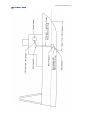
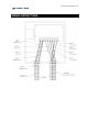
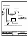
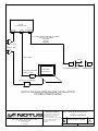
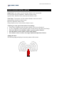
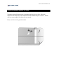
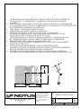
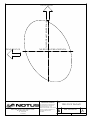
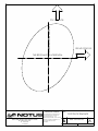
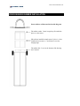
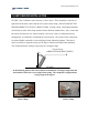
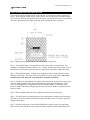
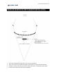
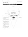
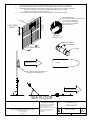
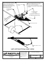
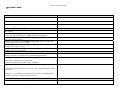
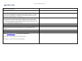
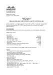
NOTUS ELECTRONICS LTD.
Trawlmaster
Installation
Manual
Version 7.2
NOTUS ELECTRONICS LTD.
Copyright
© 2009 Notus Electronics Ltd.
The information in this document is the sole property of Notus. No part of this document may
be copied or reproduced in any form or by any means without prior written consent from
Notus.
© Notus Electronics Ltd
West Empire Plaza (391 Empire Ave)
St. John’s, NL, Canada A1E 1W6
Phone 709.753.0652 • Fax 709.753.0651
Notus Electronics Ltd makes every effort to ensure information contained in this manual is
timely, accurate and correct. However, Notus equipment is constantly advancing so we
cannot assume liability for any errors that may occur.
Warning
Equipment described in this manual must only be used for the purpose for which it was
designed. Improper use or maintenance may cause equipment damage or personnel
injury. The user must be familiar with all parts of this manual.
NOTUS ELECTRONICS LTD.
NOTUS ELECTRONICS LTD.
TABLE OF CONTENTS
WIRING INSTRUCTIONS .................................................................................................................. 2 INSTALLING PC SOFTWARE .......................................................................................................... 3 DOOR SENSOR INSTALLATION..................................................................................................... 4 CLUMP SENSOR INSTALLATION .................................................................................................. 7 CATCH SENSOR INSTALLATION .................................................................................................. 8 HEADLINE MASTER OR DEPTH SENSOR INSTALLATION.................................................... 9 HEADLINE HEIGHT SENSOR INSTALLATION ........................................................................ 10 GRID SENSOR INSTALLATION .................................................................................................... 11 BOTTOM CONTACT SENSOR ....................................................................................................... 14 ONBOARD SETUP ............................................................................................................................. 16 NOTUS ELECTRONICS LTD.
WIRING INSTRUCTIONS
NOTUS
COMMAND UNIT
3PIN AC
DB9
7 PIN
BULKHEAD
NOTUS
PREAMP
CABLE
GLAND
120V AC 60Hz
or
220V AV 50Hz
CABLE
GLAND
2 WIRE SHIELDED
#18 AWG BLK/RED
4WIRE SHIELDED CABLE
#18 AWG STRANDED
BLACK/BROWN
RED/GREEN
SERIAL CABLE
2 WIRE SHIELDED
#18 AWG STRANDED
BLK/BRN
24kHz
HYDROPHONE
OPTIONAL ADAPTER
SERIAL TO USB
TRANSPONDER
COMPUTER
AND DISPLAY
AC TO DC CONVERTER
3PIN AC
DC POWER
NOTUS TRAWLMASTER/SEINE MASTER INSTALLATION
FIXED HYDROPHONE
PROPRIETARY AND CONFIDENTIAL
NOTUS ELECTRONICS LTD.
391-395 Empire Ave.
St. John's NL
A1E 1W6
THE INFORMATION CONTAINED IN THIS
DRAWING IS THE SOLE PROPERTY OF
NOTUS ELECTRONICS LTD. ANY
REPRODUCTION IN PART OR AS A WHOLE
WITHOUT THE WRITTEN PERMISSION OF
NOTUSE ELECTRONICS LTD. IS
PROHIBITED.
TITLE:
NOTUS ELECTRONICS
SYSTEM DIAGRAM
SIZE DWG. NO.
A
REV
INST-ELECTRICAL SYSTEMS
SCALE: NTS
A
SHEET 1 OF 6
NOTUS
COMMAND UNIT
3PIN AC
DB9
7 PIN
BULKHEAD
6 COND TWISTED SHIELDED PAIR WIRE
#20 AWG STRANDED
BLU/WHT
RED/BLU
RED/WHT
120V AC 60Hz
or
220V AV 50Hz
SERIAL CABLE
24kHz
TOWED HYDROPHONE
OPTIONAL ADAPTER
SERIAL TO USB
TRANSPONDER
COMPUTER
AND DISPLAY
AC TO DC CONVERTER
3PIN AC
DC POWER
NOTUS TRAWLMASTERMASTER INSTALLATION
TOWED HYDROPHONE
PROPRIETARY AND CONFIDENTIAL
NOTUS ELECTRONICS LTD.
391-395 Empire Ave.
St. John's NL
A1E 1W6
THE INFORMATION CONTAINED IN THIS
DRAWING IS THE SOLE PROPERTY OF
NOTUS ELECTRONICS LTD. ANY
REPRODUCTION IN PART OR AS A WHOLE
WITHOUT THE WRITTEN PERMISSION OF
NOTUSE ELECTRONICS LTD. IS
PROHIBITED.
TITLE:
NOTUS ELECTRONICS
SYSTEM DIAGRAM
SIZE DWG. NO.
A
REV
INST-ELECTRICAL SYSTEMS
SCALE: 1:1
A
SHEET 2 OF 6
NOTUS ELECTRONICS LTD.
INSTALLING PC SOFTWARE
INSTALLING THE PC SOFTWARE
Install the PC software as follows:
1.
2.
3.
4.
5.
The computer must be in the Windows ;3 or higher operating environment
Insert the 86%6WLFN
Locate the executable file (.exe) and run it.
Follow the instructions to completely install the program
Consult the user’s manual for setting sensor codes.
NOTUS ELECTRONICS LTD.
DOOR SENSOR INSTALLATION
Single Trawl: One master, one slave and one distance sensor are needed.
Door On Same Side as Hydrophone: Install one master sensor.
Opposite Door: Install one slave sensor and one distance sensor.
Twin Trawl: Two masters, one slave and one distance sensor are needed.
Starboard Door: Install one master sensor.
Port Door: Install one master sensor.
Clump: Install one slave sensor and one distance sensor.
Following are some general instructions for mounting:
• Ensure lines of sight between each sensor and the vessel are not obstructed.
• A sleeve (supplied by Notus) should be used to fit the sensors to the doors (and clump).
• The sensor must be surrounded by rubber to protect against vibration.
• Note that master sensors can have a door angle feature.
• Note distance sensors can have door angle, depth and temperature features.
Angling the sensor
The following diagram displays the acoustic patterns of the sensors.
NOTUS ELECTRONICS LTD.
DOOR SENSOR INSTALLATION
Templates and detailed instructions for mounting the door sleeves follow. Read the
instructions carefully and tear the templates from this manual and place on doors. Sensors
will be at correct angles if the holes are cut correctly.
Please see the below for general location.
45°
20°
1.
DURING INSTALLATION ENSURE THAT HOUSING CAGE IS SECURELY FASTENED TO
HOUSING BODY TO MINIMIZE RISK OF WARPING OR DAMAGE FROM WELD
SPLATTER.
2.
SINGLE TRAWL- ONE HOUSING SHOULD BE IN THE DOOR THAT IS ON THE SAME SIDE
AS THE HYDROPHONE. (TYPICALLY STARBOARD) TWO HOUSINGS IN THE OPPOSITE DOOR.
3.
SPACE BETWEEN HOUSINGS SHOULD BE 2.5IN.
4.
TWIN TRAWL - ONE HOUSING IN EACH DOOR
5.
HORIZONTAL PLACEMENT - INSTALL AT MIDPOINT
6.
VERTICAL PLACEMENT - BOTTOM OF HOLE TO BE 1/4 THE HEIGHT
OF THE DOOR FROM THE TOP. ON A 4FT DOOR, BOTTOM EDGE OF HOLE
SHOULD BE PLACED 1FT DOWN FROM TOP OF DOOR.
7.
TAPE THIS DIAGRAM TO THE DOOR. MAKE AN IMPRINT ON THE TEMPLATE HOLE
BY CENTER PUNCHING ON THE OUTSIDE OF LINE SHOWN ON TEMPLATES.
8.
REMOVE PAPER. TRACE WITH CHAULK AND CUT HOLE.
HOUSING SHOULD TILT 20DEG TOWARD THE FRONT OF THE DOOR AND 45DEG
AWAY FROM THE DOOR.
9.
HOUSING SHOULD BE INSTALLED SO THAT 9IN PROTRUDES FROM
THE INSIDE OF THE DOOR. ENSURE THAT THE HOUSING CAGE DOES NOT EXTEND
BEYOND THE BRIDLE ATTACHMENT POINTS ON THE DOOR.
10. THE STRIKE LINE ON THE HOUSING MUST BE LOCATED AS SHOWN IN BELOW.
THE STRIKE ON THE STARBOARD DOOR MUST FACE THE STRIKE ON THE PORT DOOR.
9IN
1/4 X H
H
1/2 X L
L
PROPRIETARY AND CONFIDENTIAL
NOTUS ELECTRONICS LTD.
391-395 Empire Ave.
St. John's NL
A1E 1W6
THE INFORMATION CONTAINED IN THIS
DRAWING IS THE SOLE PROPERTY OF
NOTUS ELECTRONICS LTD. ANY
REPRODUCTION IN PART OR AS A WHOLE
WITHOUT THE WRITTEN PERMISSION OF
NOTUSE ELECTRONICS LTD. IS
PROHIBITED.
TITLE:
TEMPLATE INSTRUCTIONS
SIZE DWG. NO.
A
REV
INST-100-001-00
SCALE: 1:1
A
SHEET 3 OF 3
THIS EDGE MUST BE VERTICAL
TOP OF DOOR
FRONT OF DOOR
THIS EDGE MUST BE HORIZONTAL
PROPRIETARY AND CONFIDENTIAL
NOTUS ELECTRONICS LTD.
391-395 Empire Ave.
St. John's NL
A1E 1W6
THE INFORMATION CONTAINED IN THIS
DRAWING IS THE SOLE PROPERTY OF
NOTUS ELECTRONICS LTD. ANY
REPRODUCTION IN PART OR AS A WHOLE
WITHOUT THE WRITTEN PERMISSION OF
NOTUSE ELECTRONICS LTD. IS
PROHIBITED.
TITLE:
STBD. DOOR TEMPLATE
SIZE DWG. NO.
A
REV
INST-100-001-00
SCALE: 1:1
A
SHEET 2 OF 3
THIS EDGE MUST BE VERTICAL
TOP OF DOOR
FRONT OF DOOR
THIS EDGE MUST BE HORIZONTAL
PROPRIETARY AND CONFIDENTIAL
NOTUS ELECTRONICS LTD.
391-395 Empire Ave.
St. John's NL
A1E 1W6
THE INFORMATION CONTAINED IN THIS
DRAWING IS THE SOLE PROPERTY OF
NOTUS ELECTRONICS LTD. ANY
REPRODUCTION IN PART OR AS A WHOLE
WITHOUT THE WRITTEN PERMISSION OF
NOTUSE ELECTRONICS LTD. IS
PROHIBITED.
TITLE:
PORT DOOR TEMPLATE
SIZE DWG. NO.
A
REV
INST-100-001-00
SCALE: 1:1
A
SHEET 1 OF 3
NOTUS ELECTRONICS LTD.
DOOR SENSOR RUBBER INSTALLATION
Insert rubbers as illustrated in the aside diagram.
Flat rubber washer. Insert in caged top first and then
place over the sensor.
Side rubbers installed around sensor (2 pieces). Once
installed, do not remove. Careful not to cover the
charging lugs.
Flat rubber disk. Leave in the bottom of the housing
once inserted.
NOTUS ELECTRONICS LTD.
CLUMP SENSOR INSTALLATION
CLUMP: One (1) distance sensor and one (1) slave sensor. There should be a clear line of
sight between the door sensors and the slave sensor on the clump. DO NOT MOUNT THE
SENSORS DIRECTLY ONTO A CHAIN CLUMP. If using a chain, a metal plate should be
used directly in front of the clump and the sensors should be mounted here. Also, ensure that
the sensors will not turn over when on bottom. Due to the variety of clumps and towing
arrangements, it is difficult to recommend an exact location. The sensors on the clump must
be pointed slightly toward the vessel as displayed in the following diagram. Therefore, it
may be necessary to angle the sensor just 30 degrees from the horizontal when installing.
This would assume the clump is being towed at a 40 degree angle.
*200
Toward Vessel
(ORIENTATION WHEN TOWING)
SEABED
In the following pictures the sensors had to be installed at a 30 degree angle from the
horizontal to ensure the correct angle when towing. The clump has an approximate
towing angle of 40 degrees.
Chain Clump
Roller Clump
NOTUS ELECTRONICS LTD.
CATCH SENSOR INSTALLATION
Catch sensors must be installed on top of the cod-end. If on the side or bottom, signals can
be lost. Some irregular signals can be expected due to the cod-end swaying and fish settling.
This is normal. Note the exact placement of the sensor will depend on the type of codend and
where the captain prefers the trigger point (the point at which the sensor activates).
Step 1: Identify the top of the codend. The sensor must be placed here.
Step 2: Vertical Placement: Closest to the area where the catch is to be monitored. For
example, on a shrimp trawl this would be 1 to 1.5 meters from the end of the codend. Note if
the sensor is too far forward, there will not be enough mesh expansion to trigger the sensor.
Step 3: Horizontal Placement: Find the center mesh across the cod-end and mark it with a
different colour twine. The center of the sensor MUST be on the center mesh. The sensor
head must be on the same side as the transducer (typically starboard).
Step 4: Sensitivity is determined by the number of mesh between the end of the sensor (point
A on the diagram) and the outer most attachment points (point B on the diagram). If the
sensor is not triggering or is triggering too late, increase the number of meshes between
points A and B. If the sensor is triggering too early, decrease the number of meshes between
points A and B.
Step 5: Ensure nothing blocks the line of sight between the sensor and the ship.
Step 6: Test the location by stretching the net to the approximate expansion experienced by a
full load (or the desired load when using more than one catch sensor). The sensor should be
triggered at this point.
Step 7: Once the catch sensor is tested while fishing and is setup correctly, the attachment
points on the sensor and rubber straps should be clearly marked to make reattachment easier.
NOTUS ELECTRONICS LTD.
HEADLINE MASTER OR DEPTH SENSOR INSTALLATION
•
•
•
•
knit a mesh bag that does not allow a lot of sensor movement
place the sensor in the middle of headline, approximately 24 inches behind the floats
attach the sensor in the same orientation as the catch sensor (straight across the mesh)
a float can be used to keep the sensor suspended
NOTUS ELECTRONICS LTD.
HEADLINE HEIGHT SENSOR INSTALLATION
NOTES:
1.
SIGHT HOLE SHOULD POINT TOWARDS SURFACE WITH GRID IN VERTICAL POSITION.
2.
WITH SENSOR INSTALLED RED LUG SHOULD BE VISIBLE FROM SIGHT HOLE IN BRACKET.
3.
GRID BRACKET SHOULD BE POSITIONED ON FRONT OF GRID WITH FOLLOWING POSITION
VERTICAL POSITION: 1/3 OF GRID HEIGHT DOWN FROM TOP OF GRID.
HORIZONTAL POSITION: MIDDLE OF GRID
4.
CAGED SIDE OF GRID BRACKET SHOULD BE PLACED ON PORT SIDE OF GRID.
TO
1/3 OF GRID
HEIGHT
T
ON
FR
HARDWARE SPEC:
2 X GRID BRACKET BACKING PLATE
8 X SS 3/8-16 2.5IN HHCS
16 X SS 3/8 FLAT WASHER
8 X SS 3/8 LOCK WASHER
8 X SS 3/8-16 NUT
ID
PORT SIDE
OF GRID
1
R
FG
PO
ID
GR
F
O
DETAIL 1
SCALE 1 : 10
BOTTOM RUBBER
BODY RUBBER
1/2 GRID WIDTH
TOP RING
DIRECTION OF TOW
VESSEL
SIGHT HOLE MUST SHOW RED LUG
TO ENSURE ANGLES BELOW
DIRECTION OF TOW
90°
45°
0
SEA FLOOR
PROPRIETARY AND CONFIDENTIAL
NOTUS ELECTRONICS LTD.
391-395 Empire Ave.
St. John's NL
A1E 1W6
THE INFORMATION CONTAINED IN THIS
DRAWING IS THE SOLE PROPERTY OF
NOTUS ELECTRONICS LTD. ANY
REPRODUCTION IN PART OR AS A WHOLE
WITHOUT THE WRITTEN PERMISSION OF
NOTUSE ELECTRONICS LTD. IS
PROHIBITED.
TITLE:
INSTALLATION
GRID ANGLE
SIZE DWG. NO.
REV
A
A
INST-100-003-00
SCALE: 1:12
SHEET 1 OF 1
SENSOR SITS ON INSIDE OF TRAWL
STITCH 3/16"(4mm) OR 1/4" (6mm)
DOUBLE GAURD TWINE UNDER SENSOR
HOUSING TO LIMIT WEAR ON NET.
LEADING EDGE OF SHEETING TO BE
ATTACHED SECURELY TO FISHING LINE.
TRAILING EDGE OF SHEETING
TO BE ATTACHED TO NET
ATTACH ONE END OF 4FT(1.5m) X 3/8" (9mm)
STAINLESS CHAINSAFETY/WEIGHT CHAIN
TO HOOP AT BOTTOM OF SENSOR
HOUSING. ATTACH OTHER END WITH LASHING
OR SHACKLE TO NET DIRECTLY BEHIND SENSOR
HOUSING
BOTTOM CONTACT
HOUSING
SUPPLIED SHACKLE
OR PERMANENT
LASHING
ANGLE READS
0 TO 90
0 SENSOR ON BOTTOM
90 SENSOR OFF BOTTOM
D
N
TIO
C
IRE
W
TO
F
O
DOUBLE GUARD TWINE
TOGGLE CHAINS
FO
OT
G
FIS
HIN
G
LI N
E
EA
R
SAFETY/WEIGHT CHAIN
NET OFF BOTTOM SIDE VIEW
PROPRIETARY AND CONFIDENTIAL
NOTUS ELECTRONICS LTD.
391-395 Empire Ave.
St. John's NL
A1E 1W6
THE INFORMATION CONTAINED IN THIS
DRAWING IS THE SOLE PROPERTY OF
NOTUS ELECTRONICS LTD. ANY
REPRODUCTION IN PART OR AS A WHOLE
WITHOUT THE WRITTEN PERMISSION OF
NOTUSE ELECTRONICS LTD. IS
PROHIBITED.
TITLE:
BOTTOM CONTACT
SIZE DWG. NO.
A
REV
INST-100-008-00
SCALE: 1:10
A
SHEET 1 OF 1
NOTUS ELECTRONICS LTD.
ONBOARD SETUP
NOTUS ELECTRONICS LTD.
COMMAND UNIT
Power to the unit: is the green light on (indicates power)?
Voltage to the unit correct?
Serial cables fastened securely?
CHECKING THE SENSORS
Check if lugs shorted/faulty. When charging, do green lights come on when charging
the sensors?
Sensors over the side of Vessel: Is there a response? Do all sensors respond or just
some? If no sensors respond, go to COMPUTER AND SOFTWARE.
With all other electronics OFF and engine idling, deploy one sensor 100 meters from
the vessel. Does it respond?
With all other electronics ON and RPM at towing speed, deploy one sensor 100
meters from the vessel. Does it respond?
With all other electronics OFF and engine idling, deploy one sensor 400-500 meters
from the vessel. Does it respond?
With all other electronics ON and RPM at towing deploy one sensor 400-500 meters
from the vessel. Does it respond?
COMPUTER AND SOFTWARE
Do you see a message: Communication Failure: Deck Unit Not Responding, Check
Settings (means the command unit is not communicating with the PC).
Check COMM Port Settings.
Trawlmaster: Command Unit, Comport Setup.
Seinemaster: Settings, Transponder Settings, Connection.
Are the correct codes entered in the software? Check the following:
Trawlmaster: Settings, Edit Trawl Setup, Codes. Sensor codes should appear under
trawl setup.
Seinemaster: Click Settings, Transponder Settings, Locations. Your depth codes
should be selected here and appear on the main screen.
PRE-AMP (HULL MOUNTED HYDROPHONE ONLY)
Is the wiring correct (consult the wiring diagram)
COMMENTS
NOTUS ELECTRONICS LTD.
Check for loose wires etc. Lightly tug on them (both sides of terminal strip) to see if
there is a loose connection.
Check the +5VDC power to the preamp unit. Meter between terminals 8 & 9.
Start the telemetry cycle. You should be able to hear the transmitted pulse if the
preamp is near the hydrophone. During transmit look at the preamp to see if there is
any arcing of the matching coil (wound ferrite coil mounted at end of the preamp
PCB). If this is happening there is a faulty coil.
Check amplifier on the preamp. Make sure the telemetry cycle is on pause & the unit
is not transmitting. It is difficult to check the amplifier circuit in the field without a
signal source or scope meter. A quick check is to meter the DC voltage on pin 1 of
U1 (small surface mount opamp on the PCB). If this DC voltage is not near 2.5 volts
then it is a good chance the amplifier is blown.
HULL MOUNTED HYDROPHONE
Disconnect the hydrophone cable and measure the capacitance of the cable between
the black and white wires. It should read between 11- 15 nF indicating a good
element
SAVED FILES
Notus software saves all information automatically. This information should be
sent to [email protected]. You can find the information at:
Trawlmaster C:\Program Files\Trawlmaster3\TowFiles
Seinemaster C:\Program Files\Seinemaster\DepFiles