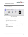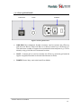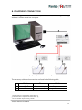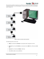
1
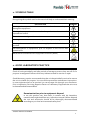
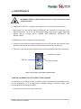
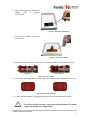
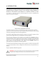
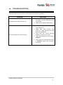
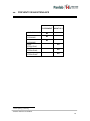
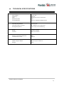
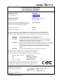
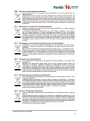
Hardware User’s Manual Shocker without scrambler Vogel Test References: LE100-25 (76-0334) Version: V03/11/2014 Panlab, s.l.u C/Energía, 112 08940 Cornellà de Ll.(Barcelona) Spain www.panlab.com International Calls: +34 934 750 697 Domestic Call: 934 190 709 Fax: +34 934 750 699 [email protected] Limitation of Liability PANLAB does not accept responsibility, under any circumstances, for any harm or damage caused directly or indirectly by the incorrect interpretation of what is expressed in the pages of this manual. Some symbols may have more than one interpretation by professionals unaccustomed to their usage. PANLAB reserves the right to modify, in part or in total, the contents of this document without notice. 1. SYMBOLS TABLE Recognising the symbols used in the manual will help to understand their meaning: DESCRIPTION SYMBOL Warning about operations that must not be done because they can damage the equipment Warning about operations that must be done, otherwise the user can be exposed to a hazard. Protection terminal ground connection. Warning about a hot surface which temperature may exceed 65ºC Warning about a metal surface that can supply electrical shock when it’s touched. Decontamination of equipments prior to disposal at the end of their operative life Waste Electrical and Electronic Equipment Directive (WEEE) 2. GOOD LABORATORY PRACTICE Check all units periodically and after periods of storage to ensure they are still fit for purpose. Investigate all failures which may indicate a need for service or repair. Good laboratory practice recommends that the unit be periodically serviced to ensure the unit is suitable for purpose. You must follow preventive maintenance instructions. In case equipment has to be serviced you can arrange this through your distributor. Prior to Inspection, Servicing, Repair or Return of Laboratory Equipment the unit must be cleaned and decontaminated. Decontamination prior to equipment disposal In use this product may have been in contact with bio hazardous materials and might therefore carry infectious material. Before disposal the unit and accessories should all be thoroughly decontaminated according to your local environmental safety laws. Shocker without scrambler 2 3. UNPACKING AND EQUIPMENT INSTALATION WARNING: Failure to follow the instructions in this section may cause equipment faults or injury to the user. A. No special equipment is required for lifting but you should consult your local regulations for safe handling and lifting of the equipment. B. Inspect the instrument for any signs of damage caused during transit. If any damage is discovered, do not use the instrument and report the problem to your supplier. C. Ensure all transport locks are removed before use. The original packing has been especially designed to protect the instrument during transportation. It is therefore recommended to keep the original carton with its foam parts and accessories box for re-use in case of future shipments. Warranty claims are void if improper packing results in damage during transport. D. Place the equipment on a flat surface and leave at least 10 cm of free space between the rear panel of the device and the wall. Never place the equipment in zones with vibration or direct sunlight. E. Once the equipment is installed in the final place, the main power switch must be easily accessible. F. Only use power cords that have been supplied with the equipment. In case that you have to replace them, the spare ones must have the same specs that the original ones. G. Make sure that the AC voltage in the electrical network is the same as the voltage selected in the equipment. Never connect the equipment to a power outlet with voltage outside these limits. For electrical safety reasons you only can connect equipment to WARNING power outlets provided with earth connections . This equipment can be used in installations with category II overvoltage according to the General Safety Rules. The manufacturer accepts no responsibility for improper use of the equipment or the consequences of use other than that for which it has been designed. Shocker without scrambler 3 PC Control Some of these instruments are designed to be controlled from a PC. To preserve the integrity of the equipment it is essential that the attached PC itself conforms to basic safety and EMC standards and is set up in accordance with the manufacturers’ instructions. If in doubt consult the information that came with your PC. In common with all computer operation the following safety precautions are advised. WARNING • To reduce the chance of eye strain, set up the PC display with the correct viewing position, free from glare and with appropriate brightness and contrast settings • To reduce the chance of physical strain, set up the PC display, keyboard and mouse with correct ergonomic positioning, according to your local safety guidelines. Shocker without scrambler 4 4. MAINTENANCE WARNING: Failure to follow the instructions in this section may cause equipment fault. PRESS KEYS SOFTLY – Lightly pressing the keys is sufficient to activate them. Equipments do not require being disinfected, but cleaned for removing urine, faeces and odour. To do so, we recommend using a wet cloth or paper with soap (which has no strong odour). NEVER USE ABRASIVE PRODUCTS OR DISSOLVENTS. NEVER pour water or liquids on the equipment. Once you have finished using the equipment turn it off with the main switch. Clean and check the equipment so that it is in optimal condition for its next use. The user is only authorised to replace fuses with the specified type when necessary. OPENING FLANGE SWITCH FUSE-HOLDER Figure 1. Power inlet, main switch and fuse holder. FUSE REPLACEMENT OR VOLTAGE SETTING CHANGE In case of an over-voltage or other incident in the AC net making it impossible to turn on the equipment, or if the equipment voltage setting is incorrect, check fuses according to the following procedure. 1 Remove power cord from the power inlet. Shocker without scrambler 5 2 Open fuse-holder by pulling the flange with a regular screwdriver. Figure 2. Open fuse-holder door. 3 Extract fuse holder using the screwdriver. Figure 3. Extract fuse-holder. 4 Replace fuses if necessary. Insert fuses in the fuse-holder in the correct position. CORRECT INCORRECT Figure 4. Fuses position. 5 Insert the fuse-holder again, positioning it according to the voltage in the AC net. 115V POSITON 230V POSITION Figure 5 Fuse holder position. 6 If the fuses blow again, unplug the equipment and contact technical service. WARNING For electrical safety reasons, never open the equipment. The power supply has dangerous voltage levels. Shocker without scrambler 6 5. TABLE OF CONTENTS 1. SYMBOLS TABLE 2 2. GOOD LABORATORY PRACTICE 2 3. UNPACKING AND EQUIPMENT INSTALATION 3 4. MAINTENANCE 5 5. TABLE OF CONTENTS 7 6. INTRODUCTION 8 7. EQUIPMENT DESCRIPTION 9 7.1. LE100-25 FRONT PANEL 7.2. LE100-25 REAR PANEL 9 10 8. EQUIPMENT CONNECTION 11 9. WORKING WITH THE UNIT 13 9.1. CONDUCTING AN EXPERIMENT 13 9.2. CLEANING THE CAGE 13 9.3. CLEANING THE GRID 13 9.4. CLEANING THE BOTTLE 13 9.5. STERILIZE THE CAGE, THE FRID AND THE BOTTLE 14 10. TROUBLESHOOTING 15 11. PREVENTIVE MAINTENANCE 16 12. TECHNICAL SPECIFICATIONS 17 Shocker without scrambler 7 6. INTRODUCTION The Vogel test is a conflict test that has become a standard for fast screening of the potential anxiolytic properties of drugs. In this procedure, drinking behaviour is punished by mild electrical shocks leading to a significant reduction of water consumption in depressed animals. Drinking responses are then re-established by drugs with anxiolytic properties. Figure 6. LE100-25 Vogel Shocker Control Unit. The Panlab Vogel test consists of a standard home cage associated with a grid floor. An electronic unit associated with a special nipple ensures the detection and counting of the licks, reflecting the animal’s drinking behaviour. An exclusive nipple design ensures that any casual or non-specific contacts of the animal with the nipple will not be considered as a drinking response. The multi-cage configuration of the Vogel test, associated with the Packwin software, allows performance of the Vogel test for up to 32 cages. The cages are associated with a link box (1 for every 8 cages) ensuring the functional interaction between the lick sensor system, the shock generator (1 per cage) and the PackWin software for advanced protocol configuration and data acquisition. The interconnection between the cages and the computer is carried out through an RS 232 serial communication. Such a configuration allows the test to be performed on a desktop. Output is optically isolated from ground. WARNING: If you touch at the same time the bottle tetine and the grid while an experiment is being conducted you may receive electrical shock. Shocker without scrambler 8 7. EQUIPMENT DESCRIPTION 7.1. LE100-25 FRONT PANEL POWER SHOCK TEST LICKS SHOCKER INTENSITY Figure 7. LE100-25 Front Panel. POWER: 3mm red led that remains ON while control unit is on. SHOCK TEST: Shock can be tested by pressing this button. In this case shock will be activated while the button is pressed. LICKS: 3mm green led that comes on each time a lick is detected. SHOCK: 3mm red led that comes on whenever the shocker is active (manually by pressing the SHOCK TEST button or remotely activated through the software). INTENSITY: Decimal selector used to select shock intensity from 0.1mA DC to 1.9mA DC, in steps of 0.1mA DC. Shocker without scrambler 9 7.2. LE100-25 REAR PANEL LINK BOX CAGE POWER Figure 8. LE100-25 Rear Panel. LINK BOX: RJ11 telephonic female connector used to connect the LE100-25 with the Link Box 01. Each Link Box 01 is able to control up to 8 LE100-25’s. The maximum number of cages to be connected to one computer is 32. This is done by using 4 Link Box 01’s connected in series. CAGE: A stereo jack is used to connect the LE100-25 with the grid and the nipple. It supplies the shock to the animal whenever it drinks. POWER: Power inlet, main switch and fuse-holder. Shocker without scrambler 10 8. EQUIPMENT CONNECTION The following illustration features an example of the connection of 2 Vogel Test Cages with one Link Box 01 and one computer. Figure 9. Example of connection of 2 cages. The necessary cables and connections are listed in the following table FROM TO CABLE 1 1 LE100-25 Cage Nipple and Grid Stereo jack to 2 bananas 2 LE100-25 Link Box2 Link Box Port n3 RJ11 telephonic cable 3 Link Box 01 Main Computer Com Port RS-232 cable 1 This connection is repeated for each LE100-25 This connection is repeated for each LE100-25 3 N is the number of port among 1 and 8 2 Shocker without scrambler 11 One computer is able to control up to 32 LE100-25’s. In this case it will be necessary to connect 4 Link Box 01’s to the computer in series (8 LE100-25’s will be connected to each Link Box 01). Figure 10. Series connection of the Link Boxes. The following rules must be met: Main port of the first Link Box is connected to the Computer Com Port. Remote Port of each Link Box is connected to the Main Port of the next Link Box. Remote Port of the last Link Box is left free. All the ID numbers must be different. Shocker without scrambler 12 9. WORKING WITH THE UNIT 9.1. CONDUCTING AN EXPERIMENT To conduct an experiment with the unit, proceed as follows: 1. Connect all the cables as explained in Chapter 8 of this manual. 2. Place the animals in the experimentation cages. 3. Turn on all the units. 4. Within the PackWin software, load an existing Protocol or edit a new one (See Vogel Test working procedure for further information). 5. Run the protocol to proceed with the experiment. 6. Once the experiment has ended, remove the animals from the experimentation cages. 7. Clean the experimentation cages to prepare for a new experiment. 8. Turn off all control units. 9.2. CLEANING THE CAGE To clean the cage you can use a slightly wet cloth and then dry them with a dry cloth. If it is too dirty you can wet the cloth with a soapy solution to clean them, then remove foam with a wet cloth and finally dry them with a dry cloth. 9.3. CLEANING THE GRID To clean the grid you can use a slightly wet cloth and then dry them with a dry cloth. If it is too dirty you can wet the cloth with a soapy solution to clean them, then remove foam with a wet cloth and finally dry them with a dry cloth. 9.4. CLEANING THE BOTTLE To clean the bottle you can use a slightly wet cloth and then dry them with a dry cloth. If it is too dirty you can wet the cloth with a soapy solution to clean them, then remove foam with a wet cloth and finally dry them with a dry cloth. Shocker without scrambler 13 9.5. STERILIZE THE CAGE, THE FRID AND THE BOTTLE Either cage or grid are autoclavable. Before sterilizing them you should disconnect the tweezers that are not ready to resist the heat. WARNING: Only the body of bottle and metal parts of the tetine are autoclavable. Plastic parts of the tetine must not be autoclavable, otherwise they will be damaged. Shocker without scrambler 14 10. TROUBLESHOOTING This table features instructions to solve the most frequent problems. PROBLEM The equipment does not start up. The animal does not receive shock. SOLUTION Ensure that the voltage of mains is the same as that selected in the fuse holder. Check the condition of the fuses. Verify that all cables are connected (see Chapter 8) Check that both control units LE100-25 Vogel Shocker and Link Box 01 are powered. Verify that the current decimal selector is not set to 0.0mA. Check the protocol you are using in Packwin. Verify that the selected serial port in Packwin match the computer serial port. Shocker without scrambler 15 11. PREVENTIVE MAINTENANCE EXPERIMENT MONTHLY GRID CLEANING CAGE CLEANING BOTTLE CLEANING GRID STERLIZING CAGE STERILIZING BOTTLE STERILIZING4 4 See chapter 9.5 warning. Shocker without scrambler 16 12. TECHNICAL SPECIFICATIONS POWER SUPPLY Input voltage: Frequency: Fuse: Maximum Power: Conducted Noise: 115/230 VAC 50/60 Hz 2 fuses 5mm*20mm 100mA fast 20W EN55022 /CISPR22/CISPR16 class B ENVIRONMENTAL CONDITIONS Operating temperature: Operating relative humidity: Storage temperature: 10°C to +40°C 0% to 85% RH, non-condensing 0°C to +50°C, non-condensing SHOCKER Range: Selector: 0mA to 1.9mA DC Steps of 0.1mA DC LICK DETECTION Maximum impedance detection: Lick detection current: 5M DIMENTIONS (control unit) Width x Height x Depth: Weight: 161mm x 67 mm x 188 mm 850g Shocker without scrambler 17 DECLARACIÓN DE CONFORMIDAD DECLARATION OF CONFORMITY DECLARATION DE CONFORMITÉ Nombre del fabricante: Manufacturer’s name: Nom du fabricant: Panlab s.l.u. www.panlab.com [email protected] Dirección del fabricante: Manufacturer’s address: Adresse du fabricant: Energía, 112 08940 Cornellà de Llobregat Barcelona SPAIN Declara bajo su responsabilidad que el producto: Declares under his responsibility that the product: Déclare sous sa responsabilité que le produit: VOGEL SHOCKER Marca / Brand / Marque: PANLAB Modelo / Model / Modèle: LE 100-25 Cumple los requisitos esenciales establecidos por la Unión Europea en las directivas siguientes: Fulfils the essential requirements established by The European Union in the following directives: Remplit les exigences essentielles établies pour l’Union Européenne selon les directives suivantes: 2006/95/EC 2004/108/EC 2012/19/EU 2011/65/EU 2006/42/EC Directiva de baja tensión / Low Voltage / Basse tensión Directiva EMC / EMC Directive / Directive CEM La Directiva de Residuos de Aparatos Eléctricos y Electrónicos (WEEE) / The Waste Electrical and Electronic Equipment Directive (WEEE) / Les déchets d'équipements électriques et électroniques (WEEE) Restricción de ciertas Sustancias Peligrosas en aparatos eléctricos y electrónicos (ROHS) / Restriction of the use of certain Hazardous Substances in electrical and electronic equipment (ROHS) / Restriction de l'utilisation de certaines substances dangereuses dans les équipements électriques et électroniques (ROHS) Directiva mecánica / Machinery directive / Directive mécanique Para su evaluación se han aplicado las normas armonizadas siguientes: For its evaluation, the following harmonized standards were applied: Pour son évaluation, nous avons appliqué les normes harmonisées suivantes: Seguridad / Safety / Sécurité: EMC: FCC: Safety of machinery: EN61010-1:2011 EN61326-1:2012 Class B FCC47CFR 15B Class B EN ISO 12100:2010 En consecuencia, este producto puede incorporar el marcado CE y FCC: Consequently, this product can incorporate the CE marking and FCC: En conséquence, ce produit peut incorporer le marquage CE et FCC: En representación del fabricante: Manufacturer’s representative: En représentation du fabricant: Carme Canalís General Manager Panlab s.l.u., a division of Harvard BioScience Cornellà de Llobregat, Spain 25/06/2014 Shocker without scrambler 18 Shocker without scrambler 19