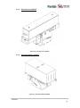
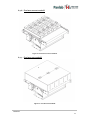
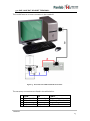
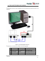
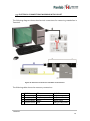
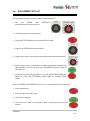
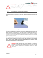
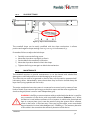
1
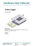
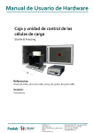
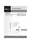
Hardware User’s Manual Treadmill References: LE8700 (76-0303), LE8708 (76-0304), LE8715 (76-0305), LE8706 (76-0306), LE8709 (76-0307), LE8710R (76-0308), LE8710M (76-0309) Version: 1.0 Panlab, s.l.u C/Energía, 112 08940 Cornellà de Ll.(Barcelona) Spain www.panlab.com International Calls: +34 934 750 697 Domestic Call: 934 190 709 Fax: +34 934 750 699 [email protected] Limitation of Liability PANLAB does not accept responsibility, under any circumstances, for any harm or damage caused directly or indirectly by the incorrect interpretation of what is expressed in the pages of this manual. Some symbols may have more than one interpretation by professionals unaccustomed to their usage. PANLAB reserves the right to modify, in part or in total, the contents of this document without notice. 1. SYMBOLS TABLE Recognising the symbols used in the manual will help to understand their meaning: DESCRIPTION SYMBOL Warning about operations that must not be done because they can damage the equipment Warning about operations that must be done, otherwise the user can be exposed to a hazard. Protection terminal ground connection. Warning about a hot surface which temperature may exceed 65ºC Warning about a metal surface that can supply electrical shock when it’s touched. Decontamination of equipments prior to disposal at the end of their operative life Waste Electrical and Electronic Equipment Directive (WEEE) 2. GOOD LABORATORY PRACTICE Check all units periodically and after periods of storage to ensure they are still fit for purpose. Investigate all failures which may indicate a need for service or repair. Good laboratory practice recommends that the unit be periodically serviced to ensure the unit is suitable for purpose. You must follow preventive maintenance instructions. In case equipment has to be serviced you can arrange this through your distributor. Prior to Inspection, Servicing, Repair or Return of Laboratory Equipment the unit must be cleaned and decontaminated. Decontamination prior to equipment disposal In use this product may have been in contact with bio hazardous materials and might therefore carry infectious material. Before disposal the unit and accessories should all be thoroughly decontaminated according to your local environmental safety laws. Treadmill 2 3. UNPACKING AND EQUIPMENT INSTALATION WARNING: Failure to follow the instructions in this section may cause equipment faults or injury to the user. A. For handling the biggest models of Treadmill , like LE8710 and LE8715 as they are heavy enough and the weight is not concentrated two persons are needed. Not following this advice can cause backache. B. Inspect the instrument for any signs of damage caused during transit. If any damage is discovered, do not use the instrument and report the problem to your supplier. C. Ensure all transport locks are removed before use. The original packing has been especially designed to protect the instrument during transportation. It is therefore recommended to keep the original carton with its foam parts and accessories box for re-use in case of future shipments. Warranty claims are void if improper packing results in damage during transport. D. Place the equipment on a flat surface and leave at least 10 cm of free space between the rear panel of the device and the wall. Never place the equipment in zones with vibration or direct sunlight. E. Once the equipment is installed in the final place, the main power switch must be easily accessible. F. Only use power cords that have been supplied with the equipment. In case that you have to replace them, the spare ones must have the same specs that the original ones. G. Make sure that the AC voltage in the electrical network is the same as the voltage selected in the equipment. Never connect the equipment to a power outlet with voltage outside these limits. For electrical safety reasons you only can connect equipment to WARNING power outlets provided with earth connections . This equipment can be used in installations with category II overvoltage according to the General Safety Rules. The manufacturer accepts no responsibility for improper use of the equipment or the consequences of use other than that for which it has been designed. Treadmill 3 PC Control Some of these instruments are designed to be controlled from a PC. To preserve the integrity of the equipment it is essential that the attached PC itself conforms to basic safety and EMC standards and is set up in accordance with the manufacturers’ instructions. If in doubt consult the information that came with your PC. In common with all computer operation the following safety precautions are advised. WARNING • To reduce the chance of eye strain, set up the PC display with the correct viewing position, free from glare and with appropriate brightness and contrast settings • To reduce the chance of physical strain, set up the PC display, keyboard and mouse with correct ergonomic positioning, according to your local safety guidelines. Treadmill 4 4. EQUIPMENT INSTALLATION WARNING: Failure to follow the instructions in this section may cause equipment faults or injury to the user. H. Place the equipment on a flat surface and leave at least 10 cm of free space between the rear panel of the device and the wall. Never place the equipment in zones with vibration or direct sunlight. I. Make sure that the AC voltage in the electrical network is the same as the voltage selected in the equipment. Never connect the equipment to a power outlet with voltage outside these limits. For electrical safety reasons you only can connect equipment to WARNING power outlets provided with earth connections . This equipment can be used in installations with category II overvoltage according to the General Safety Rules. The manufacturer accepts no responsibility for improper use of the equipment or the consequences of use other than that for which it has been designed. Treadmill 5 5. MAINTENANCE WARNING: Failure to follow the instructions in this section may cause equipment fault. PRESS KEYS SOFTLY – Lightly pressing the keys is sufficient to activate them. Equipments do not require being disinfected, but cleaned for removing urine, faeces and odour. To do so, we recommend using a wet cloth or paper with soap (which has no strong odour). NEVER USE ABRASIVE PRODUCTS OR DISSOLVENTS. NEVER pour water or liquids on the equipment. Once you have finished using the equipment turn it off with the main switch. Clean and check the equipment so that it is in optimal condition for its next use. The user is only authorised to replace fuses with the specified type when necessary. OPENING FLANGE SWITCH FUSE-HOLDER Figure 1. Power inlet, main switch and fuse holder. FUSE REPLACEMENT OR VOLTAGE SETTING CHANGE In case of an over-voltage or other incident in the AC net making it impossible to turn on the equipment, or if the equipment voltage setting is incorrect, check fuses according to the following procedure. 1 Remove power cord from the power inlet. Treadmill 6 2 Open fuse-holder by pulling the flange with a regular screwdriver. Figure 2. Open fuse-holder door. 3 Extract fuse holder using the screwdriver. Figure 3. Extract fuse-holder. 4 Replace fuses if necessary. Insert fuses in the fuse-holder in the correct position. CORRECT INCORRECT Figure 4. Fuses position. 5 Insert the fuse-holder again, positioning it according to the voltage in the AC net. 115V POSITON 230V POSITION Figure 5 Fuse holder position. 6 If the fuses blow again, unplug the equipment and contact technical service. WARNING For electrical safety reasons, never open the equipment. The power supply has dangerous voltage levels. Treadmill 7 6. TABLE OF CONTENTS 1. SYMBOLS TABLE 2 2. GOOD LABORATORY PRACTICE 2 3. UNPACKING AND EQUIPMENT INSTALATION 3 4. EQUIPMENT INSTALLATION 5 5. MAINTENANCE 6 6. TABLE OF CONTENTS 8 7. INTRODUCTION 10 8. EQUIPMENT DESCRIPTION 12 8.1. ONE & TWO-LANES CONTROL UNIT FRONT PANEL 12 8.2. FIVE-LANES CONTROL UNIT FRONT PANEL 13 8.3. DISPLAY 14 8.4. ONE-LANE CONTROL UNIT REAR PANEL 15 8.5. TWO-LANES CONTROL UNIT REAR PANEL 16 8.6. FIVE-LANES CONTROL UNIT: REAR PANEL 17 8.7. TREADMILL BELT 8.7.1. One-lane mouse treadmill 8.7.2. One-lane rat treadmill 8.7.3. One-lane rabbit treadmill 8.7.4. Two-lanes mouse treadmill 8.7.5. Two-lanes rat treadmill 8.7.6. Five-lanes mouse treadmill 8.7.7. Five-lanes rat treadmill 18 18 19 19 20 20 21 21 9. 22 EQUIPMENT CONNECTION 9.1. ONE-LANE MOUSE TREADMILL 22 9.2. ONE-LANE RAT & RABBIT TREADMILL 23 9.3. TWO-LANES TREADMILL (RAT & MOUSE) 24 9.4. FIVE-LANES TREADMILL (RAT & MOUSE) 25 Treadmill 8 9.5. ELECTRICAL CONNECTIONS WORKING WITH OXYLET 26 9.6. PNEUMATIC CONNECTIONS WORKING WITH OXYLET 27 10. EQUIPMENT SET-UP 28 10.1. ALIGNMENT OF THE EXERCISE TREADMILL 29 10.2. SLOPE SETTINGS 30 10.3. MAINTENANCE 30 10.4. GRID CLEANING 31 10.5. CLEANING THE BELT 31 10.6. CLEANING THE PERSPEX COVER 31 10.7. TRAY CLEANING 31 11. TRANSMISION OF DATA TO THE PC (SEDACOM) 32 12. TROUBLESHOOTING 33 13. PREVENTIVE MAINTENANCE 35 14. SPECIFICATIONS 36 Treadmill 9 7. INTRODUCTION The LE 8700 Series of treadmills are used to study animal’s motor function (mice, rats or rabbits). The following models are available: Figure 6. LE8700 Treadmill control unit. There are different models detailed in the following table: REFERENCE DESCRIPTION LE 8700 LE 8706 LE 8708 LE 8709 LE 8710 LE 8715 MIN SPEED One-lane rat treadmill with shock 5cm/s Two-lanes rat treadmill with shock 5cm/s One-lane mouse treadmill with shock 5cm/s Two-lanes mouse treadmill with shock 5cm/s Five-lanes treadmill with shock 5cm/s One-lane rabbit treadmill 10cm/s MAX SPEED 150cm/s 150cm/s 150cm/s 150cm/s 150cm/s 80cm/s It consists of an exercise treadmill driven by a motor, the speed of which can be adjusted continuously from 5 to 150 cm/s (10 to 80cm/s in Rabbit Treadmill). Depending on the model it can have one or several lanes, each with its own independently electrified grid. When the animal tires and stops while on the belt, it reaches the grid, where it receives a shock as an electrical stimulus to keep running. WARNING: The grid is under voltage while the treadmill is in RUN mode. Treadmill 10 Figure 7. Rabbit Treadmill Belt. It is important to keep the grid clean of animal waste. A dirty grid may cause the shock to be given when the animal is outside the grid, thus causing erroneous data in the experiment (erroneous number of shocks and time shock values). An inferior tray collects animal excrements. The animal is kept in the lane with a transparent Perspex lid. There are open-air lids for normal treadmills and closed lids for metabolism studies, in which the treadmill is used together the Oxilet system. Treadmill 11 8. EQUIPMENT DESCRIPTION 8.1. ONE & TWO-LANES CONTROL UNIT FRONT PANEL SPEED STOP/RUN RESET DISPLAY SHOCK Figure 8. One and Two-lanes Control Unit Front Panel. SPEED: This potentiometer selects the belt speed from 5cm/s to 150cm/s in increments of 1cm/s (10cm/s to 80cm/s in Rabbit Treadmill). The speed value is shown on the display. STOP/RUN: Red button. When the belt is stopped, it begins to run by pressing this button and the word RUN is shown in the lower right corner of the display. By pressing the same button again the belt stops and STOP is shown in the lower right corner of the display. RESET: Green button. Counters in the display are reset to zero by pressing this button (experiment time, number of shocks, distance and time shock). INTENSITY: This potentiometer selects the shock intensity in the grid from 0 to 2mA RMS. Below 0.2mA the counters (number of shocks and time shock) will not increase when the animal reaches the grid. Treadmill 12 8.2. FIVE-LANES CONTROL UNIT FRONT PANEL SPEED STOP/RUN RESET DISPLAY SHOCK Figure 9. Five lanes Treadmill Control Unit Front Panel. SPEED: This potentiometer selects the belt speed from 5cm/s to 150cm/s in increments of 1cm/s. The speed value is shown on the display. STOP/RUN: Red button. When the belt is stopped, it begins to run by pressing this button and the word RUN is shown in the lower right corner of the display. By pressing the same button again the belt stops and STOP is shown in the lower right corner of the display. RESET: Green button. Counters in the display are reset to zero by pressing this button (experiment time, number of shocks, distance and time shock). INTENSITY: This potentiometer selects shock intensity in the grid from 0 to 2mA RMS. Below 0.2mA the counters (number of shocks and time shock) will not increase when the animal reaches the grid. Treadmill 13 8.3. DISPLAY DISTANCE TIME SHOCK SPEED NUMBER OF SHOCKS EXPERIMENT TIME STATUS Figure 10. Front panel display. The front panel display has 4 rows and 40 columns. The upper three rows display lane counters (Distance, Time Shock, Number of Shocks), with one counter for each lane. The lowest row displays Speed, Duration of Experiment and Status. DISTANCE: Distance run by the animal in the current experiment. This counter does not increase while the animal is on the grid, as it is not running. TIME SHOCK: Accumulated time in which the animal has received shock. NUMBER OF SHOCKS: Number of times that the animal reaches the grid and receives a shock. There is a filter to prevent the animal from jumping on the grid. This value will increase again if at least 0.4 seconds have passed between shocks received by the animal. SPEED: Selected speed. This value is modified with the potentiometer SPEED in the front panel. It can be set from 5cm/s to 150cm/s (10cm/s to 80cm/s in Rabbit Treadmill). EXPERIMENT TIME: This counter begins at zero when the RUN button is pressed and stops when the same button is pressed again. STATUS: This label indicates belt status: RUN when the belt is running and STOP when the belt is stopped. Treadmill 14 8.4. ONE-LANE CONTROL UNIT REAR PANEL SHOCK MOTOR RS-232 POWER Figure 11. One-lane control unit: rear panel. SHOCK: DB15 female connector used to connect the control unit to the grid in the lane. It transmits the electrical shock to the grid. MOTOR: Panel jack male connector used to connect control unit to the motor that drives the belt. RS 232: DB9 female connector used to connect the control unit to a PC serial port. With Sedacom software (not included with the device), the information on the display can be sent to the computer, which can be used to control the treadmill. POWER: Power inlet, main switch and fuse-holder. Treadmill 15 8.5. TWO-LANES CONTROL UNIT REAR PANEL SHOCK MOTOR RS-232 POWER Figure 12. Two-lanes control unit: rear panel. SHOCK: DB15 female connector to connect control unit to the grid in the lane. It transmits the electrical shock to the grid. There is an independent shock connector and board for each lane. MOTOR: Panel jack male connector, is used to connect control unit to the motor that drives the belt. RS 232: DB9 female connector, used to connect control unit to PC serial port. With Sedacom software (not included with the device), the information on the display can be sent to the computer, which can be used to control the treadmill. POWER: Power inlet, main switch and fuse-holder. Treadmill 16 8.6. FIVE-LANES CONTROL UNIT: REAR PANEL SHOCK MOTOR RS-232 POWER FAN Figure 13. Five-lanes control unit: rear panel. SHOCK: DB15 female connector to connect control unit to the grid in the lane. It transmits the electrical shock to the grid. There is an independent shock connector and board for each lane. MOTOR: Panel jack male connector, used to connect control unit to the motor that drives the belt. RS 232: DB9 female connector used to connect the control unit to a PC serial port. With SEDACOM software (not included with the device), the information on the display can be sent to the computer, which can be used to control the treadmill POWER: Power inlet, main switch and fuse-holder. FAN: The fan extracts air from control unit in order to cool it. Treadmill 17 8.7. TREADMILL BELT GRID TRANSMISION BELT SLOPE CONTROL Figure 14. Treadmill belt. GRID: At the end of each lane there is an electrical grid to administer a shock as a stimulus for the animal to run. TRANSMISION: The motor axis is connected to a toothed wheel. This wheel drives another one by means of a toothed belt. The latter wheel is connected to the treadmill belt axis to move the surface over which the animal runs. BELT: Surface over which the animal runs. It is common for all lanes. The lanes are separated by the transparent Perspex cover. SLOPE CONTROL: This mechanism controls the slope of the belt. The slope can be set from -25º to +25º in 5º increments. 8.7.1. One-lane mouse treadmill Figure 15. One-lane mouse treadmill. Treadmill 18 8.7.2. One-lane rat treadmill Figure 16. One-lane rat treadmill. 8.7.3. One-lane rabbit treadmill Figure 17. One-lane rabbit treadmill. Treadmill 19 8.7.4. Two-lanes mouse treadmill Figure 18. Two-lanes mouse treadmill. 8.7.5. Two-lanes rat treadmill Figure 19. Two-lane rat treadmill. Treadmill 20 8.7.6. Five-lanes mouse treadmill Figure 20. Five-lanes mouse treadmill. 8.7.7. Five-lanes rat treadmill Figure 21. Five-lane rat treadmill. Treadmill 21 9. EQUIPMENT CONNECTION 9.1. ONE-LANE MOUSE TREADMILL In this case, the motor cable is connected directly to the motor. Figure 22. One-lane mouse treadmill connection. The cables and connections are listed in the following table. FROM 1 LE8700 SHOCK 1 2 LE8700 Motor 3 LE 8700 RS-232 LE8700 Power TO Treadmill grid Motor PC serial port AC power net CABLE DB9 to DB15 cable Motor cable DB9 to DB9 cable Power cord Treadmill 22 9.2. ONE-LANE RAT & RABBIT TREADMILL This model features a motor connector in the treadmill. Figure 23. One-lane rat & rabbit treadmill connections. The necessary connections are listed in the table below: FROM 1 LE8700 SHOCK 1 2 LE8700 Motor 3 LE 8700 RS-232 LE8700 Power TO Treadmill grid Motor PC serial port AC power net CABLE DB9 to DB15 cable DIN6 to jack female cable DB9 to DB9 cable Power cord Treadmill 23 9.3. TWO-LANES TREADMILL (RAT & MOUSE) The schematic shows a mouse treadmill, but the connections are the same as for a rat treadmill. Figure 24. Two-lane treadmill connections. The necessary connections are listed in the following table: 1 2 3 4 FROM LE8700 SHOCK 1 LE8700 SHOCK 2 LE8700 Motor LE 8700 RS-232 LE8700 Power TO Treadmill grid 1 Treadmill grid 2 Motor PC serial port AC power net CABLE DB9 to DB15 cable DB9 to DB15 cable DIN6 to Jack female cable DB9 to DB9 cable Power cord Treadmill 24 9.4. FIVE-LANES TREADMILL (RAT & MOUSE) The schematic shows a mouse treadmill, but the connections are the same as for a rat treadmill. Figure 25. Five-lane treadmill connection. The necessary connections are listed in the following table: 1 2 3 4 5 6 7 FROM LE8700 SHOCK 1 LE8700 SHOCK 2 LE8700 SHOCK 3 LE8700 SHOCK 4 LE8700 SHOCK 5 LE8700 Motor LE 8700 RS-232 LE8700 Power TO Treadmill grid 1 Treadmill grid 2 Treadmill grid 3 Treadmill grid 4 Treadmill grid 5 Motor PC serial port AC power net CABLE DB9 to DB15 cable DB9 to DB15 cable DB9 to DB15 cable DB9 to DB15 cable DB9 to DB15 cable DIN6 to Jack female cable DB9 to DB9 cable Power cord Treadmill 25 9.5. ELECTRICAL CONNECTIONS WORKING WITH OXYLET The following diagram shows the electrical connections for measuring metabolism in Treadmill. Figure 26. Electrical connections in metabolic measurements. The following table shows the necessary connections. 1 2 3 4 FROM LE405 RS-232 LE405 Sync LE8700 Motor LE8700 Shock TO Computer serial port LE 400X Sync Motor Grid CABLE DB9 to DB9 cable telephonic Motor cable DB15 to DB9 cable Treadmill 26 9.6. PNEUMATIC CONNECTIONS WORKING WITH OXYLET The diagram below shows the pneumatic connections necessary to measure metabolism in Treadmill. Figure 27.Pneumatic connections for measuring metabolism. The arrows indicate the direction of airflow. 1 2 3 4 5 FROM LE400X Sample Outlet LE400X Cage Outlet Treadmill Outlet Air Inlet Air Inlet TO LE405 Sample Inlet Treadmill Inlet LE400X Cage Inlet Room Room Diameter of Tube 4mm+Nafion 6mm 4mm 4,5mm 9,5mm WARNING: The tubes 4 and 5 which respectively serve for sampling the room air and the air inlet to the pump must be placed as far away as possible from the fan outlet to prevent air pollution as electro valves system expels air from cages inside the equipment. Both tubes are attached and should be placed away from sources of air pollution. By polluted air we mean breathing from both animals or people. Treadmill 27 10. EQUIPMENT SET-UP The procedure to set up the instrument is outlined below: 1 Set the SPEED and INTENSITY potentiometers to the minimum. 2 Place the animal(s) in their lane(s). 3 Press the STOP/RUN button to start the Run mode. 4 Adjust the SPEED to the desired value. 5 Adjust the intensity to a level at which the animal notices the shock. 6 After a short time for the animal to adapt to the belt and when all the animals are out of the grid, press the RESET button to reset all the counters. 7 Once the trial time has finished or once the desired DISTANCE has been run, press the STOP/RUN button again to activate STOP mode. Once the SPEED and INTENSITY are set, you can accelerate the trial process: 1 Press RUN button. 2 Place one animal in each lane. 3 Press RESET button. 4 Once the trial TIME or DISTANCE have finished press the STOP button. Treadmill 28 WARNING: Selecting the INTENSITY knob less than 0.2 mA while the equipment is really giving shock, the counters NUMB-S and TIME-S of the display do not count. A minimum current is needed to detect the arrival of the animal to the grid. 10.1. ALIGNMENT OF THE EXERCISE TREADMILL Treadmill movement is supported by two rollers: the rear or drive roller and the front one. Figure 28. Allen screws. The exercise treadmill has a tightening system which makes it possible to adjust the lateral movement of the belt: the 2 Allen-head screws at the sides (see Figure 28). Turning the screw clockwise increases the tension on the side where the screw is installed and turning it counter-clockwise decreases the tension of the belt on the side where the screw is installed. For example, if the belt has moved to the left (as seen from the front) tension on the left side must be increased, or tension on the right side decreased to centre the belt again. The two screws can be adjusted until the desired position is attained. These adjustments should be made for high belt speeds. WARNING: When working with closed Treadmills for metabolic measures, centring holes are covered to prevent entry of air from the outside. Once the treadmill belt is centred you should cover again these holes. Treadmill 29 10.2. SLOPE SETTINGS Figure 29. Slope control mechanism. The treadmill slope can be easily modified with the slope mechanism. It allows positive and negative slope settings from -25º to +25º in increments of 5º. Proceed as follows to adjust the belt slope: 1. 2. 3. 4. 5. Partially unscrew the fixing screw. Move the slope lever up slightly to free it. Set the belt to the necessary inclination. Move the slope lever down to block the slope. Tighten the fixing screw again to block the mechanism. 10.3. MAINTENANCE The treadmill requires no special maintenance. It can be cleaned with alcohol-free detergents or derived products to avoid damaging its acrylic parts. The rollers do not need to be greased or oiled as they are mounted on protected selflubricating rollers. Nevertheless, areas where there may be friction should always be kept clean (using a paintbrush or a brush). The entire mechanical exercise system is connected to a control unit by means of two kinds of leads. One transmits the energy to the drive motor and the other supplies the shock to the grid (there is one for each independent grid). WARNING: the RS232 communication cable provided with the device is used for any connection of the device with associated software (Sedacom, etc.). When the device is used without software in first instance it needs to be preserved and kept in a secure place just in case the need of using the system with a software arises in the future. In this last case, if the user lost the cable, a new one should be purchased to his local sales delegate (ref. CONRS232). The warranty duration of this cable is the same than the warranty duration of the device. Treadmill 30 10.4. GRID CLEANING The grid should be cleaned after each experiment. When there is dirt in the grid the electrical shock flows through it. This will produce erroneous data during the experiment because the counters (Time shock, number of shocks and distance) will increase although the animal had not touched the grid. In order to clean the grid you can use water and soap and then you must dry it. Grids sets can be unscrewed from Treadmill body in order to clean it, or simply use a wet brush to clean it. Special care must be taken in cleaning the plastic between grids, because urine is a good electrical conductor and current flows through it. 10.5. CLEANING THE BELT After each experimental session the belt should be cleaned with a damp cloth to remove any traces of urine and faeces. 10.6. CLEANING THE PERSPEX COVER To clean the perspex cover you can use a slightly wet and then dry them with a dry cloth. If it is too dirty a cloth soaked in a soapy solution can be used to clean them, afterwards remove the foam with a wet cloth and finally dry them with a dry cloth. WARNING: Never use alcohol or alcohol-based detergents to clean perspex parts, if used grooves will appear in the transparent plastic. This damage is not covered by the warranty. 10.7. TRAY CLEANING In order to clean the tray it can be extracted from the guides, then throw away the excrements and clean it with water and foam, then dry it with a dry cloth and insert it again in the guides. In metabolic treadmills the tray covers all the bottom of the treadmill and it is fixed with rubber magnet bands in its entire contour. Treadmill 31 11. TRANSMISION OF DATA TO THE PC (SEDACOM) The purchase of the Sedacom software is needed for transferring the data to a computer (please contact your local sales delegate for more information). The Sedacom software reference is composed by a USB Flash key containing the software Installer, a License for use and Sedacom User’s Manual). Follow the next instructions: Please refer to the Sedacom User’s Manual for instructions on how to install and use the software with the present device. A serial port (RS232) communication cable (provided with the present device) is needed for the connection of the present device to the computer in which the Sedacom software is installed. Please refer to the present User’s Manual chapter 9 for instructions on how to connect this cable to the device. If the computer doesn’t have any serial port, the RS232/USB adapter is needed (ref. CONRS232USB, contact your local provider for more information) Treadmill 32 12. TROUBLESHOOTING This table features instructions to solve the most frequent problems. PROBLEM The equipment does not start up. SOLUTION Ensure that the voltage of mains is the same as that selected in the fuse holder. Check the condition of the fuses. The animal does not receive shock. Shock counters count although the animal has not reached to the grid. When the animal reaches the grid does not increment counters NUMB-S and TIME-S. When you turn on the control unit without pressing the RUN/STOP Check that the DB9 to DB15 cables are connected between the grids and the control unit. Check that the INTENSITY knob in the control unit is set to a value higher than 0mA. Check that the grid is clean (urine and excrements can conduct current). Check that control unit is in RUN mode. When you operate the device with the program Sedacom and the modes are PC control or Protocol check if you have checked the checkbox Shock. Make sure the grid is clean (urine and faeces can carry the current). Disconnect the DB9-DB15 cable from the grid and put the controller in RUN mode, if the problem persists this means a malfunction in the control unit, if the problem goes away it was dirt on the grid or a cable failure. Ensure that DB15-DB9 cables are connecting the grids and the control unit. Ensure that the selected intensity is greater than 0.2 mA; below this value the counters will not count. When you operate the device with the program Sedacom and the modes are PC control or Protocol check if you have checked the checkbox Shock. The transistor that controls the motor is shorted, contact technical service to Treadmill 33 button the belt runs at maximum speed. repair the equipment. Centre the belt as explained in section 10.1. Make sure the motor cable is connected. Make sure the device is in RUN mode. If at low speed the belt does not run, but when speed increases it starts to run, the belt is too tight, loosen it and let it be centred as explained in section 10.1. The belt is too tight, loosen it and let it be centred as explained in section 10.1. Possibly the motor or the control unit are damaged. Contact the technical service for repair. Remnants of faces have been attached to the drive roller and produce a lifting of the belt that crashes to the grid. Loosen the belt with the tension screws and clean the dirt under it and in the transmission rollers. When you operate the device with the program Sedacom and the modes are PC control or Protocol these buttons are disabled. If not contact with technical service in order to solve the problem. The belt moves to one side The belt does not run. At low speeds the belt does not run uniformly. At high speeds the belt is slow. The belt hits some of the grids. The buttons STOP/RUN RESET do not work. and Treadmill 34 13. PREVENTIVE MAINTENANCE EXPERIMENT MONTHLY BIANUAL GRID CLEANING BELT CLEANING PERSPEX COVER CLEANING TRAY CLEANING BELT CENTERING1 GENERAL MAINTENANCE IN FACTORY 1 If the belt moves to one side, it will be necessary to center it immediately. Treadmill 35 14. SPECIFICATIONS POWER SUPPLY Input voltage: Frequency: Fuse: Maximum Power: Conducted Noise: 115 /230V~ 50/60 Hz 2 fuses 5mm*20mm 1A 250V Fast 50W EN55022 /CISPR22/CISPR16 class B ENVIRONMENTAL CONDITIONS Operating temperature: Operating Relative Humidity: Storage temperature: 10°C to +40°C 0% to 85% RH, non-condensing 0°C to +50°C, non-condensing COMUNICATIONS OUTPUT Standard Interface: Connector: RS232C Delta 9 contacts female connector DISPLAY COUNTERS: DISTANCE: SHOCK-TIME: NUMBER OF SHOCKS: EXPERIMENT TIME: 0 to 9999 m in steps of 1 m 0.0 to 999.9s in steps of 0.1s 0 to 9999 in steps of 1 0 to 99 min 59 sec. BELT: LENGTH: Mouse: Rat: Rabbit: SPEED: Rats and Mice: Rabbits: 685 mm 926 mm 1326 mm 5 to 150 cm/s in steps of 1 cm/s 10 to 80 cm/s in steps of 1 cm/s MOTOR Power: LE8708: Other models: 20W 33W Waveform Channels Intensity Impedance Rectangular waveform with 8,3ms amplitude Six sequential channels at 20Hz Adjustable from 0 to 2mA RMS 160k SHOCK DIMENTIONS Width x Height x Deep: 1 and 2 lanes control unit: 5 lanes control unit Weight: 1 lane control unit: 2 lanes control unit: 5 lanes control unit: 232mm*111mm*297mm 232mm*155mm*320mm 4,5kg 5kg 7,4kg Treadmill 36 DECLARACIÓN DE CONFORMIDAD DECLARATION OF CONFORMITY DECLARATION DE CONFORMITÉ Nombre del fabricante: Manufacturer’s name: Nom du fabricant: Panlab s.l.u. www.panlab.com [email protected] Dirección del fabricante: Manufacturer’s address: Adresse du fabricant: Energía, 112 08940 Cornellà de Llobregat Barcelona SPAIN Declara bajo su responsabilidad que el producto: Declares under his responsibility that the product: Déclare sous sa responsabilité que le produit: Treadmill Control Marca / Brand / Marque: PANLAB Modelo / Model / Modèle: LE8700, LE8706, LE8708, LE8709, LE8710, LE 8715 Cumple los requisitos esenciales establecidos por la Unión Europea en las directivas siguientes: Fulfils the essential requirements established by The European Union in the following directives: Remplit les exigences essentielles établies pour l’Union Européenne selon les directives suivantes: 2006/95/EC 2004/108/EC 2012/19/EU 2011/65/EU 2006/42/EC Directiva de baja tensión / Low Voltage / Basse tensión Directiva EMC / EMC Directive / Directive CEM La Directiva de Residuos de Aparatos Eléctricos y Electrónicos (WEEE) / The Waste Electrical and Electronic Equipment Directive (WEEE) / Les déchets d'équipements électriques et électroniques (WEEE) Restricción de ciertas Sustancias Peligrosas en aparatos eléctricos y electrónicos (ROHS) / Restriction of the use of certain Hazardous Substances in electrical and electronic equipment (ROHS) / Restriction de l'utilisation de certaines substances dangereuses dans les équipements électriques et électroniques (ROHS) Directiva mecánica / Machinery directive / Directive mécanique Para su evaluación se han aplicado las normas armonizadas siguientes: For its evaluation, the following harmonized standards were applied: Pour son évaluation, nous avons appliqué les normes harmonisées suivantes: Seguridad / Safety / Sécurité: EMC: FCC: Safety of machinery: EN61010-1:2011 EN61326-1:2012 Class B FCC47CFR 15B Class B EN ISO 12100:2010 En consecuencia, este producto puede incorporar el marcado CE y FCC: Consequently, this product can incorporate the CE and FCC marking: En conséquence, ce produit peut incorporer le marquage CE et FCC: En representación del fabricante: Manufacturer’s representative: En représentation du fabricant: Carme Canalís General Manager Panlab s.l.u., a division of Harvard BioScience Cornellà de Llobregat, Spain 30/04/2014 Treadmill 37 Treadmill 38