1
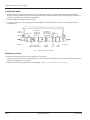
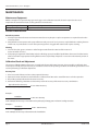
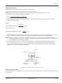
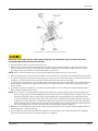
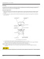
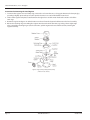
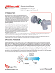
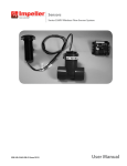
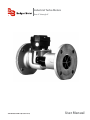
Industrial Turbo Meters
Sizes 2" through 6"
TUR-UM-00530-EN-19 (October 2014)
User Manual
Industrial Turbo Meters, Sizes 2" through 6"
Page ii
TUR-UM-00530-EN-19
October 2014
User Manual
CONTENTS
Scope of the Manual . . . . . . . . . . . . . . . . . . . . . . . . . . . . . . . . . . . . . . . . . . . . . . . . . . . . . . . . . . . . . . . . . . . . 5
Specifications . . . . . . . . . . . . . . . . . . . . . . . . . . . . . . . . . . . . . . . . . . . . . . . . . . . . . . . . . . . . . . . . . . . . . . . . 5
Product Unpacking and Inspection . . . . . . . . . . . . . . . . . . . . . . . . . . . . . . . . . . . . . . . . . . . . . . . . . . . . . . . . . . . 5
Installation . . . . . . . . . . . . . . . . . . . . . . . . . . . . . . . . . . . . . . . . . . . . . . . . . . . . . . . . . . . . . . . . . . . . . . . . . . 5
Preliminary Considerations . . . . . . . . . . . . . . . . . . . . . . . . . . . . . . . . . . . . . . . . . . . . . . . . . . . . . . . . . . . . . 5
Installing the Meter . . . . . . . . . . . . . . . . . . . . . . . . . . . . . . . . . . . . . . . . . . . . . . . . . . . . . . . . . . . . . . . . . . 6
Performance Checks . . . . . . . . . . . . . . . . . . . . . . . . . . . . . . . . . . . . . . . . . . . . . . . . . . . . . . . . . . . . . . . . . 6
Operation . . . . . . . . . . . . . . . . . . . . . . . . . . . . . . . . . . . . . . . . . . . . . . . . . . . . . . . . . . . . . . . . . . . . . . . . . . . 7
General Operating Instructions . . . . . . . . . . . . . . . . . . . . . . . . . . . . . . . . . . . . . . . . . . . . . . . . . . . . . . . . . . 7
Manual Operation . . . . . . . . . . . . . . . . . . . . . . . . . . . . . . . . . . . . . . . . . . . . . . . . . . . . . . . . . . . . . . . . 7
Accessory Controlled Operation . . . . . . . . . . . . . . . . . . . . . . . . . . . . . . . . . . . . . . . . . . . . . . . . . . . . . . . 7
Shutdown Instructions . . . . . . . . . . . . . . . . . . . . . . . . . . . . . . . . . . . . . . . . . . . . . . . . . . . . . . . . . . . . . . . . 7
Maintenance . . . . . . . . . . . . . . . . . . . . . . . . . . . . . . . . . . . . . . . . . . . . . . . . . . . . . . . . . . . . . . . . . . . . . . . . . 8
Maintenance Equipment . . . . . . . . . . . . . . . . . . . . . . . . . . . . . . . . . . . . . . . . . . . . . . . . . . . . . . . . . . . . . . 8
Preventive Maintenance . . . . . . . . . . . . . . . . . . . . . . . . . . . . . . . . . . . . . . . . . . . . . . . . . . . . . . . . . . . . . . . 8
Periodic Inspection . . . . . . . . . . . . . . . . . . . . . . . . . . . . . . . . . . . . . . . . . . . . . . . . . . . . . . . . . . . . . . . 8
Cleaning . . . . . . . . . . . . . . . . . . . . . . . . . . . . . . . . . . . . . . . . . . . . . . . . . . . . . . . . . . . . . . . . . . . . . . 8
Calibration Check and Adjustment . . . . . . . . . . . . . . . . . . . . . . . . . . . . . . . . . . . . . . . . . . . . . . . . . . . . . . . . 8
Accuracy Test . . . . . . . . . . . . . . . . . . . . . . . . . . . . . . . . . . . . . . . . . . . . . . . . . . . . . . . . . . . . . . . . . . . 8
Change Gear Corrections . . . . . . . . . . . . . . . . . . . . . . . . . . . . . . . . . . . . . . . . . . . . . . . . . . . . . . . . . . . 9
Electronic Scaling Correction . . . . . . . . . . . . . . . . . . . . . . . . . . . . . . . . . . . . . . . . . . . . . . . . . . . . . . . . . 9
Calibrating 2" and 3" Meters . . . . . . . . . . . . . . . . . . . . . . . . . . . . . . . . . . . . . . . . . . . . . . . . . . . . . . . . . . . 10
Register Base Replacement . . . . . . . . . . . . . . . . . . . . . . . . . . . . . . . . . . . . . . . . . . . . . . . . . . . . . . . . . . . . 10
Servicing . . . . . . . . . . . . . . . . . . . . . . . . . . . . . . . . . . . . . . . . . . . . . . . . . . . . . . . . . . . . . . . . . . . . . . . . 12
Change Gear Replacement . . . . . . . . . . . . . . . . . . . . . . . . . . . . . . . . . . . . . . . . . . . . . . . . . . . . . . . . . 12
Instructions for Removing the Gear Train Assembly with Magnet . . . . . . . . . . . . . . . . . . . . . . . . . . . . . . . . . 13
Instructions for Removing the Local Register . . . . . . . . . . . . . . . . . . . . . . . . . . . . . . . . . . . . . . . . . . . . . . 14
October 2014
TUR-UM-00530-EN-19
Page iii
Industrial Turbo Meters, Sizes 2" through 6"
Page iv
TUR-UM-00530-EN-19
October 2014
Scope of the Manual
SCOPE OF THE MANUAL
This manual contains information concerning the installation, operation and maintenance of Badger Meter® magnetic drive
turbo meters. To efficiently operate the meters, you must read and understand the instructions given in this manual. Retain
the manual in a location where it is readily available for reference.
SPECIFICATIONS
Maximum Operating Temperature
250.5° F (120.5° C)
Maximum Operating Pressure
150 psi (10 bar)
Optional: 300 psi (bronze), 250 psi (cast iron)
Accuracy Over Entire Range*
± 1.5%
Repeatability
0.5 or better
Connections
Round flange ASA or DIN
Body Materials
SS 316, bronze, cast iron
Rotor and Nose Cone Materials
Ryton
Head Assembly Materials
SS 316 or bronze
Straightening Vane Material
SS 316
Head Gasket Materials
Asbestos, Nitrile or Chloroprene
O-Ring Materials
EPR, Buna, Viton A
Bearing and Magnet Material
Ceramic
Spindle
SS 316
PRODUCT UNPACKING AND INSPECTION
Upon opening the shipping container, visually inspect the product and applicable accessories for any physical damage such
as scratches, loose or broken parts, or any other sign of damage that may have occurred during shipment.
NNOTE: If damage is found, request an inspection by the carrier’s agent within 48 hours of delivery and file a claim with the
carrier. A claim for equipment damage in transit is the sole responsibility of the purchaser.
INSTALLATION
The procedures for installing Badger Meter turbo meters are essentially the same for all meter sizes. Any special instructions
required for the installation and/or electrical connection of meter-mounted or free-standing accessory devices such as
registers, pulse transmitters, valves and remote batch controllers are provided with those devices.
Preliminary Considerations
• The Badger Meter 2" through 6" industrial turbo meters are designed for operation in HORIZONTAL piping arrangements.
• If solid material is present in the liquid to be metered, a strainer may be required in the facility piping upstream of the
meter. The 2", 3" and 4" meters require a strainer with 1/16" diameter holes and the 6" meter requires a strainer with 1/8"
diameter holes.
• To permit periodic cleanout of the meter and to provide a convenient means of stopping fluid flow during maintenance,
incorporate a flushing system into the facility piping arrangement.
October 2014
TUR-UM-00530-EN-19
Page 5
Industrial Turbo Meters, Sizes 2" through 6"
Installing the Meter
1. Install the meter in the pipeline so the flow arrow on the meter housing is in proper relation to the direction of liquid
flow. Insall ten pipe diameters upstream and five pipe diameters downstream of straight, unobstructed pipe. If this is not
possible, contact factory to review your installation.
2. Install and tighten the flange connection bolts.
3. To relieve possible strain on the piping due to the weight of 4" and 6" turbo meters, install a meter support under the
meter housing.
Bypass
(Permanent
or
Temporary)
Upstream
Valve (open)
Minimum of 5
diameters of
straight pipe
Badger Meter plate
strainer and Turbo meter
Minimum of 2
pipe diameters
downstream of
Turbo meter
Coupling
adapter
Test tee
Service
saddle
Shutoff
valve
Downstream
U
Figure 1: Recommended meter installation
Performance Checks
Complete the following checks for proper installation and operation.
1. Slowly open the upstream valve to apply liquid pressure to the meter and check the flange connections for possible leaks.
Retighten the flange bolts as required.
2. Perform a functional test of the turbo meter following “Calibration Check and Adjustment” on page 8.
Page 6
TUR-UM-00530-EN-19
October 2014
Operation
OPERATION
General Operating Instructions
REGARDLESS OF THE OPERATING PROCEDURE USED, THE VALVES OR DEVICES CONTROLLING THE FLOW OF LIQUID
THROUGH THE TURBO METER MUST ALWAYS BE OPENED AND CLOSED SLOWLY OR IN STAGES TO PREVENT SHOCK
LOADS THAT MAY DAMAGE THE METER'S ROTOR ASSEMBLY.
Manual Operation
These procedures are intended for use in simple metering applications where the flow of liquid through the meter is
controlled by hand-operated valves located in the facility piping upstream and downstream of the meter.
1. Slowly open the upstream valve to allow liquid to flow to the meter.
2. Slowly open the downstream valve to initiate metering.
3. Adjust the downstream valve so that the rate of flow does not exceed the maximum continuous flow rate specification of
the meter.
4. To stop metering, slowly close the downstream valve, then close the upstream valve.
Accessory Controlled Operation
The step-by-step operating procedures used in accessory controlled metering applications are dependent on the specific
function of the meter accessory employed and its electrical or pneumatic interconnection with the flow control device or
devices. Refer to the user manuals covering the applicable accessories for specific operating instructions.
Shutdown Instructions
If the turbo meter is to be shut down for an extended period of time, thoroughly flush the measuring chamber to prevent
undissolved solids or corrosive deposits from accumulating.
October 2014
TUR-UM-00530-EN-19
Page 7
Industrial Turbo Meters, Sizes 2" through 6"
MAINTENANCE
Maintenance Equipment
With the exception of a special change gear mesh gage and a calibration test tank, the tools required are the usual
compliment of standard hand tools used by plumbers and mechanics.
Truarc Right-Angle Pliers
Truarc P/N 1549 (Badger Meter P/N 57321-001)
Change Gear Mesh Gage
Badger Meter P/N 21747-000
Preventive Maintenance
Periodic Inspection
1. Visually inspect the turbo meter and meter-mounted accessory. Repair or replace components as required based on the
visual inspection.
2. Verify that the meter operates at the proper flow rate and pressure. A loss in pressure, coupled with the resulting decrease
in flow rate, may indicate the screen in the upstream pipeline is clogged with material and requires cleaning.
Cleaning
1. Clean all dust, dirt, grease, moisture or other foreign material from the exterior of the meter and
meter-mounted accessory.
2. If the piping arrangement of the facility includes a flushing system, shut off the liquid flow to the meter. Flush the interior
of the meter with an appropriate cleaning fluid to remove any buildup of deposits or corrosion on the internal portion of
the meter.
Calibration Check and Adjustment
The accuracy of Badger Meter turbo meters is tested at the factory with water. However, due to possible use of liquids that
could vary in viscosity, it may be necessary to recalibrate a meter under operating conditions. The following instructions are to
assist in performing a calibration adjustment.
Accuracy Test
1.
2.
3.
4.
Place a test tank of known volume at the output of the meter.
Operate the meter until the test tank is filled to a calibrated level. Run at the actual flow rate used in the operation.
Record the quantity indicated on the meter accessory.
Perform the following calculations to determine percent of accuracy of the meter-accessory combination:
Qty. Indicated on Accessory
Actual Quantity in Test Tank
X 100 = Meter Accuracy
Example 1:
95 Gallons
x 100 = 95% Accuracy
100 Gallons
In this example, the accessory is slow and must be sped up by a change gear or electronic scaling correction.
Example 2:
104 Gallons
X 100 = 104% Accuracy
100 Gallons
In this example, the accessory is fast and must be slowed down.
Page 8
TUR-UM-00530-EN-19
October 2014
Maintenance
Change Gear Corrections
If the test indicates that an adjustment is required, proceed as follows:
1. Remove the change gears from the spindles by loosening the setscrew.
NNOTE: Both the O.D. dimension (in decimal inches) and the number of teeth are stamped on each gear.
2. Calculate the ratio of existing change gears as follows:
Ratio =
No. of Teeth on Register Change Gear
No. of Teeth on Meter Register Base
3. Calculate the new change gear ratio required by multiplying the ratio of existing change gears by percent-of-meter
accuracy determined in test.
Example:
Existing Change Gear Ratio =
42 Teeth
43 Teeth
= 0.976
Meter Accuracy = 95 %
Corrected Change Gear Ratio = 0.976 x
95
100
= 0.927
4. Select a combination of new change gears that match the corrected change gear ratio. If stocked change gears are not
available, submit an order for change gears to your nearest Badger Meter representative or to Badger Meter.
NNOTE: When ordering, give the serial number of the turbo meter, which is stamped on the outlet flange of the meter.
Specify the meter size and accessory employed along with the number of teeth and diameter on the existing change
gears. Specify the corrected change gear ratio.
5. Install the corrected change gears, taking care to assemble the correct change gears to the appropriate spindles (see
Figure 2). For registers, see “Servicing” on page 12 for instructions on the proper method of installing and meshing
change gears. On meters with 76 Series registers, provision for change gear adjustment is built in. See the applicable
register's user manual for recalibrating instructions.
Figure 2: Change gear location, register base and register assembly
Electronic Scaling Correction
If the test results indicate an adjustment is required, see the instruction manual for that accessory for the procedure to change
the scale factor.
October 2014
TUR-UM-00530-EN-19
Page 9
Industrial Turbo Meters, Sizes 2" through 6"
Calibrating 2" and 3" Meters
The 2" and 3" turbo meters with bronze and cast iron housings and bronze heads are equipped with a bypass valve for minor
calibration adjustment in the field. Test the meter's accuracy to determine if recalibration is required. If the meter is out of
calibration, proceed as follows:
Figure 3: Calibrating 2" and 3" turbo meters
1. Remove the bypass cover nut with a wrench.
2. Using a wide-bladed screwdriver, loosen the bypass valve lock ring.
3. Adjust the bypass valve with a screw driver:
a. To INCREASE registration, turn the slot in the valve perpendicular to the axis of the meter (line of flow). This will restrict
the amount of volume flowing through the bypass and increase flow through the metering chamber.
b. To DECREASE registration, turn the slot in the valve parallel to the axis of the meter. This will increase liquid volume
through the bypass and decrease flow through the metering chamber.
NNOTE: The total range of the bypass adjustment occurs within a 90 degree or quarter turn of the valve from the parallel,
inline position to the perpendicular position, or vice versa. The total range of adjustment is about four percent. Tested
and calibrated at the factory, the bypass valve will be set at about 45° from the full "open" or "closed" position. This
setting will allow for a ±2% adjustment to recalibrate the meter in the field.
3. With the valve turned to the desired bypass setting, tighten the valve lock ring.
4. Install and tighten the bypass valve cover nut.
5. Retest the meter to confirm the accuracy of the bypass adjustment. If the meter is still out of calibration, repeat the
procedure outlined above.
Register Base Replacement
Badger Meter turbo meters can be serviced without removing them from the system. To inspect or replace component parts
of the head assembly, close the upstream and downstream valves. If the installation is equipped with an inlet and drain valve
for flushing the meter, open the drain valve to relieve pressure from within the meter. However, if the meter piping is not
equipped with a drain valve, proceed as follows to relieve pressure within the meter:
1. Do not remove the register base from the operating head assembly. The entire head assembly must be removed as a
complete unit (See figure below).
2. Loosen each of the head bolts about one and one-half turns. Do not remove the bolts completely.
3. If the gasket-seal between the meter head and the housing is not leaking at this time, pry the head assembly loose by
inserting a screwdriver from the outlet side of the head assembly where the head and housing join together.
Page 10
TUR-UM-00530-EN-19
October 2014
Maintenance
Figure 4: Turbo meters serviced without removal from the line
MAKE SURE THAT FLUID DOES NOT SPRAY FROM THE METER. THE LIQUID SPRAY COULD CONTACT ELECTRICAL
EQUIPMENT AND CREATE AN ELECTRICAL HAZARD.
4. Allow the meter to drain and relieve internal pressure.
5. When pressure is relieved, remove the head bolts and shift the head assembly toward the outlet-end of the meter to
release the head-to-housing seal. Then lift the entire head assembly from the housing and, at the same time, tilt the
operating head up to prevent the rotor from falling off the rotor spindle.
NNOTE: Rotors are furnished with two-pole or four-pole magnets, depending on the type of accessory.
6. When the operating head has been removed, lift the rotor out of the rotor cage and set it aside. Remove the head gasket.
7. To remove the register base from the head assembly, loosen the seal screw on the base with a screwdriver. Rotate the base
45 degrees in either direction to release it from the bayonet lock detents on the head assembly.
8. The register base retaining ring is accessible through the rotor cage in the head assembly. With a Truarc right-angle pliers
#1549, expand and remove the register retaining ring on the extension tube, then remove the register base from the
head assembly.
9. To reinstall or replace the register base, repeat the procedure above in reverse making sure that the retaining ring has
been reinstalled on the extension tube.
NNOTE: The head unit has a gasket bonded to the periphery of the rotor cage. Depending on the chemical solution to be
metered, the gasket will be made of EPR, Buna N or Viton A material. Re-inserting the head assembly into the meter
housing correctly will require compressing the gasket slightly. This is done by tilting the top of the register base
on the head toward the inlet side of the meter. The meter head has a pilot diameter machined into the cage at the
gasket face. This pilot diameter must extend through the housing gasket inner diameter and into the housing bore.
After lowering the head assembly into the housing, move the entire head assembly straight toward the inlet side of
the meter. The pilot diameter must snap into the bore of the housing to provide a tight seal.
10.With the head gasket aligned and the head assembly properly positioned in the housing, reinstall and tighten the head
bolts (between 90…180 in-lb of torque).
11.Close the flushing system drain valve. Open the upstream valve partially, then open the downstream valve slightly to
purge any air from the service line. Then open both valves completely.
October 2014
TUR-UM-00530-EN-19
Page 11
Industrial Turbo Meters, Sizes 2" through 6"
Servicing
This section covers the removal, inspection and installation of service parts and assemblies. Any service or repair procedures
that apply to a meter-mounted or free-standing accessory are provided in the user manual pertaining to that device. If
satisfactory repair cannot be made, contact Badger Meter.
Change Gear Replacement
1. Replacing the change gear on the register base spindle requires no gage to properly mesh this gear with the register
change gear. A shoulder-stop is built in to the spindle at the proper gear height to eliminate the necessity to adjust
the gear.
2. The change gear in the register should be installed with a Badger Meter change gear mesh gage (P/N 21747-000) for
proper gear mesh.
-000
Figure 5: Replacing turbo meter change gears
a. Place the bottom of the register on the top edge of the gage. See Figure 2 on page 9.
b. Adjust the change gear on the register spindle so that it rests against the top of the slot in the gage. Holding the
change gear in this position, tighten the setscrew in the hub of the change gear.
NNOTE: Install the change gears on the spindles with the hub of the gears in the UP position.
c. Carefully install the register on the base. Make sure that the gears fully mesh. Install and tighten the register
seal screws.
DO NOT BEND THE SPINDLES WHEN INSTALLING THE GEARS OR REASSEMBLING THE REGISTER TO THE REGISTER BASE.
Page 12
TUR-UM-00530-EN-19
October 2014
Maintenance
Instructions for Removing the Gear Train Assembly with Magnet
The gear train assembly can be removed and replaced without removing the turbo meter from the line.
Two gear train assemblies are used with industrial turbo meters. To find out what the gear train ratio is, count the number
of spindles (gear and pinions) that protrude through the five mounting holes provided in the top plate of the gear train
assembly. If there are only three spindles, the gear ratio is 366:1 and if there are five spindles, the gear ratio is 1200:1.
1. Remove the register, transmitter or adapter mounted on the register base.
2. Release the retainer ring from the groove to free the gear train assembly from the base.
Figure 6: Release the retainer ring
3. Use a small screwdriver to release the retainer ring from the groove in the wall adjacent to the top plate of the gear
train assembly.
4. Grip the change gear spindle and lift to remove the gear train assembly with magnet from the register base.
5. Remove the accessory change gear or coupling from the gear train spindle. Before removing, note the location of the
change gear (or coupling) on the spindle so that it can be reinstalled in the same location.
NNOTE: A flat surface is provided at the top of the spindle of the change gear assembly so that the setscrew in the change
gear or coupling can be properly seated and tightened to the spindle.
6. Gear train assemblies are packaged with the magnet and spindle assembly disassembled from the gear train assembly.
Before assembling, carefully check the spindle for minute burrs on the threaded end of the spindle. If there are burrs, use
a crocus cloth and carefully remove them from the spindle. This will prevent damage to the surface of the jewel bearing
when inserting the magnet spindle through the jewel bushing in the bottom plate of the gear train assembly. An E-ring
should be mounted on the spindle. If missing, remove the E-ring from the replacement spindle and snap it into the
grooved collar near the threaded end of the spindle.
Figure 7: Installing the magnet spindle assembly to the gear train assembly
October 2014
TUR-UM-00530-EN-19
Page 13
Industrial Turbo Meters, Sizes 2" through 6"
Instructions for Removing the Local Register
1. To remove the register cover and clamp ring, remove the seal screw that acts as a hinge pin. Remove the clamp ring by
spreading it slightly apart at the open side to provide clearance so it can be lifted off the meter head.
2. Slide out the register lock plate, located between the register base and the meter head at the entrance side of the
rotor cage.
3. Rotate the register 45 degrees in either direction to release it from the bayonet lock detents on the head assembly.
4. Release the retaining ring surrounding the register extension tube inside the rotor cage. Using a Truarc right-angle
pliers, expand the retaining ring and, at the same time, pull the register tube out of the head unit, removing the
register assembly.
Figure 8: Register and operating head assembly
(2" and 3" meters shown)
Page 14
TUR-UM-00530-EN-19
October 2014
Maintenance
INTENTIONAL BLANK PAGE
October 2014
TUR-UM-00530-EN-19
Page 15
Transit Time Meter, Sizes 2" through 6"
Control. Manage. Optimize.
Trademarks appearing in this document are the property of their respective entities. Due to continuous research, product improvements and enhancements, Badger Meter reserves
the right to change product or system specifications without notice, except to the extent an outstanding contractual obligation exists. © 2014 Badger Meter, Inc. All rights reserved.
www.badgermeter.com
The Americas | Badger Meter | 4545 West Brown Deer Rd | PO Box 245036 | Milwaukee, WI 53224-9536 | 800-876-3837 | 414-355-0400
México | Badger Meter de las Americas, S.A. de C.V. | Pedro Luis Ogazón N°32 | Esq. Angelina N°24 | Colonia Guadalupe Inn | CP 01050 | México, DF | México | +52-55-5662-0882
Europe, Middle East and Africa | Badger Meter Europa GmbH | Nurtinger Str 76 | 72639 Neuffen | Germany | +49-7025-9208-0
Europe, Middle East Branch Office | Badger Meter Europe | PO Box 341442 | Dubai Silicon Oasis, Head Quarter Building, Wing C, Office #C209 | Dubai / UAE | +971-4-371 2503
Czech Republic | Badger Meter Czech Republic s.r.o. | Maříkova 2082/26 | 621 00 Brno, Czech Republic | +420-5-41420411
Slovakia | Badger Meter Slovakia s.r.o. | Racianska 109/B | 831 02 Bratislava, Slovakia | +421-2-44 63 83 01
Asia Pacific | Badger Meter | 80 Marine Parade Rd | 21-06 Parkway Parade | Singapore 449269 | +65-63464836
China | Badger Meter | 7-1202 | 99 Hangzhong Road | Minhang District | Shanghai | China 201101 | +86-21-5763 5412
Legacy Document Number: IOM-003-17-EN PN 53400-003