1
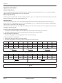
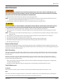
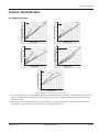
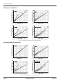
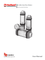
Variable Area Flow Meters Inline Pneumatic Flow Meter VAM-UM-00593-EN-02 (August 2014) User Manual Variable Area Flow Meters, Inline Pneumatic Flow Meter CONTENTS Introduction . . . . . . . . . . . . . . . . . . . . . . . . . . . . . . . . . . . . . . . . . . . . . . . . . . . . . . . . . . . . . . . . . . . . . . . . . 3 Operating Principle . . . . . . . . . . . . . . . . . . . . . . . . . . . . . . . . . . . . . . . . . . . . . . . . . . . . . . . . . . . . . . . . . . . . .4 Installation . . . . . . . . . . . . . . . . . . . . . . . . . . . . . . . . . . . . . . . . . . . . . . . . . . . . . . . . . . . . . . . . . . . . . . . . . . 5 Compressibility of Gases . . . . . . . . . . . . . . . . . . . . . . . . . . . . . . . . . . . . . . . . . . . . . . . . . . . . . . . . . . . . . . .5 Installation Recommendations . . . . . . . . . . . . . . . . . . . . . . . . . . . . . . . . . . . . . . . . . . . . . . . . . . . . . . . . . . .6 Installing the Flow Meter . . . . . . . . . . . . . . . . . . . . . . . . . . . . . . . . . . . . . . . . . . . . . . . . . . . . . . . . . . . . . . 6 Installing the Test Kit Flow Meter . . . . . . . . . . . . . . . . . . . . . . . . . . . . . . . . . . . . . . . . . . . . . . . . . . . . . . . . . 8 Operation . . . . . . . . . . . . . . . . . . . . . . . . . . . . . . . . . . . . . . . . . . . . . . . . . . . . . . . . . . . . . . . . . . . . . . . . . . .9 Multi-Pressure Flow Scales . . . . . . . . . . . . . . . . . . . . . . . . . . . . . . . . . . . . . . . . . . . . . . . . . . . . . . . . . . . . . 9 Single Pressure Flow Scales . . . . . . . . . . . . . . . . . . . . . . . . . . . . . . . . . . . . . . . . . . . . . . . . . . . . . . . . . . . . .9 Application Information . . . . . . . . . . . . . . . . . . . . . . . . . . . . . . . . . . . . . . . . . . . . . . . . . . . . . . . . . . . . . . 10 Maintenance . . . . . . . . . . . . . . . . . . . . . . . . . . . . . . . . . . . . . . . . . . . . . . . . . . . . . . . . . . . . . . . . . . . . . . . . 11 Removal of Dust Guard . . . . . . . . . . . . . . . . . . . . . . . . . . . . . . . . . . . . . . . . . . . . . . . . . . . . . . . . . . . . . . 11 Quick Recoupling . . . . . . . . . . . . . . . . . . . . . . . . . . . . . . . . . . . . . . . . . . . . . . . . . . . . . . . . . . . . . . . . . . 11 Test Kit Maintenance . . . . . . . . . . . . . . . . . . . . . . . . . . . . . . . . . . . . . . . . . . . . . . . . . . . . . . . . . . . . . . . . 11 Fluid Selection Chart . . . . . . . . . . . . . . . . . . . . . . . . . . . . . . . . . . . . . . . . . . . . . . . . . . . . . . . . . . . . . . . . . . . 12 Flow vs. Pressure Drop . . . . . . . . . . . . . . . . . . . . . . . . . . . . . . . . . . . . . . . . . . . . . . . . . . . . . . . . . . . . . . . . . . 13 Air/Compressed Gases . . . . . . . . . . . . . . . . . . . . . . . . . . . . . . . . . . . . . . . . . . . . . . . . . . . . . . . . . . . . . . . 13 Air/Compressed Test Kits . . . . . . . . . . . . . . . . . . . . . . . . . . . . . . . . . . . . . . . . . . . . . . . . . . . . . . . . . . . . . 14 Air/Caustic and Corrosive Gases . . . . . . . . . . . . . . . . . . . . . . . . . . . . . . . . . . . . . . . . . . . . . . . . . . . . . . . . . 14 Specifications . . . . . . . . . . . . . . . . . . . . . . . . . . . . . . . . . . . . . . . . . . . . . . . . . . . . . . . . . . . . . . . . . . . . . . . 15 Materials of Construction . . . . . . . . . . . . . . . . . . . . . . . . . . . . . . . . . . . . . . . . . . . . . . . . . . . . . . . . . . . . . 15 Dimensions . . . . . . . . . . . . . . . . . . . . . . . . . . . . . . . . . . . . . . . . . . . . . . . . . . . . . . . . . . . . . . . . . . . . . . . . . 16 Standard Meters . . . . . . . . . . . . . . . . . . . . . . . . . . . . . . . . . . . . . . . . . . . . . . . . . . . . . . . . . . . . . . . . . . . 16 Test Kits . . . . . . . . . . . . . . . . . . . . . . . . . . . . . . . . . . . . . . . . . . . . . . . . . . . . . . . . . . . . . . . . . . . . . . . . 17 Page ii VAM-UM-00593-EN-02 August 2014 Introduction INTRODUCTION The Inline Pneumatic Flow Meter is a rugged industrial class flow rate indicator and is offered in aluminum, brass, T303 and T316 stainless steel models to monitor pressurized air lines and a wide range of other compressed gases. Available in seven port sizes from 0.25…3 inch for flow ranges from 0.5…5 scfm (0.2…2.2 l/sec) through 200…2200 scfm (75…1130 l/sec), meters are calibrated at 1.0 specific gravity. In addition to the basic model, the aluminum, brass and T303 stainless steel models are offered in three configurations: an extended inlet cap fitted with a pressure gauge, an extended inlet cap with a 0.25 inch NPTF plugged gauge port, and a test kit with an extended inlet cap fitted with a 160 psi pressure gauge and control valve on the outlet. The Flow Meter is equipped with a 360° rotatable guard/scale which allows the meter to be installed in any orientation without regard to scale direction. Once the meter is permanently installed, the guard/scale can be rotated 360° to optimize readability. The unique spring loaded design of this variable area flow meter allows it to be installed in any position, including inverted, without affecting accuracy. An optional inverted scale is available for these applications. Aluminum models are offered as a rugged, low cost flow meter for monitoring noncorrosive pneumatic systems under operating pressures up to 1000 psi (69 bar), 250 psi (17 bar) for 3" models, and 600 psi (41 bar) for test kits. Brass meters are recommended for applications with operating pressures up to 1000 psi (69 bar) without corrosion inhibitors. Stainless Steel is available for monitoring systems operating at pressures up to 1500 psi (103 bar). The T316 stainless steel models are recommended for monitoring caustic or corrosive gases, such as hydrogen chloride or sulfur dioxide. The T303 stainless steel test kit is rated to 600 psi (41 bar); pressure rating is limited by the valve. For further construction material information, see "Materials of Construction" on page 15 . August 2014 VAM-UM-00593-EN-02 Page 3 Operating Principle OPERATING PRINCIPLE The Flow Meter is a variable area instrument. A sharp-edged orifice, located within the piston assembly, forms an annular opening with the contoured metering cone. The piston assembly carries a cylindrical PPS/ceramic magnet that is magnetically coupled to an external indicating magnet, which moves precisely in direct response to movement of the piston. A calibrated spring opposes flow in the forward direction. The Hedland variable area flow meters are the most readable products in their class. Brightly colored indicators move over the graduated, linear flow scale which contains bold, easy-to-read numeral and gauge marks. The enhanced resolution virtually eliminates parallax problems associated with competitive direct reading flow meters. Figure 1: Inline pneumatic flow meter Page 4 VAM-UM-00593-EN-02 August 2014 Installation INSTALLATION THIS PRODUCT SHOULD BE INSTALLED AND SERVICED BY A TECHNICALLY QUALIFIED PERSONNEL TRAINED IN MAINTAINING INDUSTRIAL CLASS FLOW INSTRUMENTATION AND PROCESSING EQUIPMENT. READ INSTRUCTIONS THOROUGHLY BEFORE INSTALLING THE UNIT. IF YOU HAVE ANY QUESTIONS REGARDING PRODUCT INSTALLATION OR MAINTENANCE, CALL YOUR LOCAL SUPPLIER FOR MORE INFORMATION. THIS METER MAY CONTAIN RESIDUAL AMOUNTS OF TEST FLUID AT THE TIME OF SHIPMENT. THIS FLUID SHOULD BE REMOVED PRIOR TO INSTALLATION AS THE FLUID MAY BE INCOMPATIBLE OR HAZARDOUS WITH SOME LIQUIDS OR GASES. FAILURE TO FOLLOW THESE INSTRUCTIONS COULD RESULT IN DAMAGE TO THE EQUIPMENT. THIS STANDARD METER IS UNIDIRECTIONAL. ATTEMPTS TO FLOW FLUIDS IN THE OPPOSITE DIRECTION OF THE FLOW ARROW WILL RESULT IN THE METER ACTING AS A CHECK VALVE, CREATING A DEADHEADING SITUATION. IF THE DIFFERENTIAL PRESSURE MAGNITUDE IS GREAT ENOUGH, DAMAGE TO THE INTERNAL PARTS OF THE METER WILL RESULT. A LINE SNUBBER IS RECOMMENDED FOR APPLICATIONS IN WHICH RAPID VALVE ACTUATION OR PULSATION IS ANTICIPATED. THIS NOT ONLY REDUCES THE RISK OF DECOUPLING THE FLOW METER'S MAGNETIC PISTON, IT ALSO REDUCES EXCESSIVE WEAR ON OTHER COMPONENTS IN THE SYSTEM. Compressibility of Gases Gases are significantly compressible so the density of any compressed gas will vary according to changes in operating pressure levels. In other words, volumetric flow rates will vary significantly with changes in line pressure. Therefore, pneumatic flow meters should be installed with a pressure gauge located as close as possible to the inlet port. The psig range capacity of this pressure gauge should be at least 125% of the anticipated pressure in the system, or be suitable for the maximum expected line pressure (if higher). For example, if the anticipated operating pressure is 100 psig, a pressure gauge with a capacity of at least 125 psig should be installed as close as possible to the inlet port. August 2014 VAM-UM-00593-EN-02 Page 5 Installation Installation Recommendations The inline flow meter is a simple device to install. However, the following measures are recommended for reliable, troublefree operation: 1. Piping should be accurately aligned and of correct length. The high pressure body of the flow meter can withstand shock and flow/pressure pulsation. However, the piping should be firmly supported by external mounting brackets, both upstream and downstream of the meter, to avoid any pipe flexing actions that could reduce meter life. 2. If the flow meter inlet or outlet are to be rigidly mounted, and the opposing port is to be connected to a flexible hose, the end connected with the flexible hose must be rigidly mounted. 3. Use Teflon® tape for sealing NPT fitting. 4. Install a union near the inlet or outlet of the meter for quick, easy meter removal and inspection during periodic maintenance procedures. 5. Mount the meter either horizontally or vertically (flow arrow pointing to either side or straight up). If the meter must be mounted inverted, special inverted scales are available. 6. Ensure the fluid is traveling in the direction of the flow arrow (see Figure 2). 7. Systems that do not have filtration should be equipped with at least a 200 mesh (74 micron) filter. Most systems already have much finer filtration. The meter will allow particulate to pass that would jam most valves and flow controls. Dirt, ferrous metal or sealing agents, such as Teflon® tape may lodge and cause malfunction. If the meter is jammed at a fixed position, see "Removal of Dust Guard" on page 11. 8. Don not use thread locking compounds as thread sealant. 9. Do not install the flow meter near turbulence producing fittings such as elbows, reducers and close coupled valves for maximum reliability. The inline flow meter does not require flow straighteners or special lengths of straight inlet/outlet piping to stabilize turbulent flow patterns. 10.Do not install the meter near fast-acting valves. Fast-acting valves have the potential to create high magnitude hydraulic pressure spikes. These spikes can damage the internal components of the meter, resulting in inaccuracies or malfunction. 11.Do not allow unidirectional meters to be operated against the direction of the flow arrow. The standard flow meter is an unidirectional flow meter. The piston acts as a check valve to block flow in the reverse direction. This causes an excessive pressure differential, which can result in damage to internal meter components. Installing the Flow Meter 1. Mount the meter so fluid is traveling in the direction of the flow arrow. See Figure 1 on page 4. Flow Direction Arrow AIR Figure 2: Flow direction arrow 2. Select a mounting location that is suitable for viewing and product service. To connect the flow meter into the piping system, place an open-ended wrench onto the flow meter wrench flats adjacent to the pipe connection being installed. DO NOT wrench on the opposite end of the flow meter or leakage may result. See Figure 3 on page 7. Page 6 VAM-UM-00593-EN-02 August 2014 Installation Place wrench on meter flats on the same side plumbing is being tightened Never place wrench on meter flats opposite plumbing being tightened Figure 3: Installing meter 3. After installation, rotate the meter by hand to the view flow scale. See Figure 4. Rotate meter by hand to view flow scale Never use wrench to rotate meter body when viewing flow scale Figure 4: Rotating meter August 2014 VAM-UM-00593-EN-02 Page 7 Installation Installing the Test Kit Flow Meter 1. Mount the VA High Pressure Test Kit Flow Meter so fluid is traveling in the direction of the flow arrow. See Figure 2 on page 6. 2. Install the test kit at any location in the pneumatic circuit that is suitable for viewing. To connect the test kit into the piping system, place an open-ended wrench onto the test kit extended cap on the inlet side or on the test kit wrench flat on the outlet side adjacent to the pipe connection being installed. Do not wrench on the opposite end of the test kit or leakage may result. See Figure 5. Place wrench on valve body on the same side plumbing is being tightened Never place wrench on valve body opposite plumbing being tightened Figure 5: Installing test kit Or, use quick disconnect couplings for easy connections and to keep the test kit sealed and clean when not in use. 3. After installation, rotate the meter by hand to the view flow scale. See Figure 6. Rotate meter by hand to view flow scale Never use wrench to rotate meter body when viewing flow scale Figure 6: Rotating test kit Page 8 VAM-UM-00593-EN-02 August 2014 Operation OPERATION Multi-Pressure Flow Scales The inline pneumatic flow meter is offered with a multi-pressure flow scale to visually indicate air flow rates in standard cubic feet per minute (scfm) at 1.0 s.g. (70° F at 100 psi) or liters per second (l/sec) at 1.0 s.g. (21° C at 6.9 bar). The multi-pressure scale design allows for use at line pressures from 40…130 psi in 10 psi increments (3.0…9.0 bar in 1 bar increments). This configuration requires that a pressure gauge be installed at the meter inlet. Read the inlet gauge pressure then select the appropriate vertical line or interpolated value closest to the gauge reading and follow the line until it intersects the brightly colored horizontal indicator bar. The flow rate is read by taking the intersection points, following the slope of the closest diagonal line to a scale value and interpolating the scfm (l/sec) flow rate. No further calculations are required. See Figure 7. SCFM @ 70°F 130 120 110 100 90 80 70 60 50 40 INLET PRESSURE (PSIG) 50 40 HORIZONTAL INDICATOR BAR 30 20 10 5 AIR Figure 7: Multi-pressure flow scale Single Pressure Flow Scales An optional single pressure flow scale is available in U.S. or metric units. This graduated scale is calibrated for air in standard cubic feet per minute (scfm) at 1.0 s.g. (70° F at 100 psi), or liters per second (l/sec) at 1.0 s.g. (21° C at 6.9 bar). See Figure 7. A standard cubic foot of air is defined as a cubic foot of air at 70 °F at atmospheric pressure 14.7 psia at sea level. Since it is impossible to flow air at “standard” conditions, the scale is calibrated for an inlet condition of 100 psi (6.9 bar) at 70° F (21° C). A correction factor must be calculated to determine the actual air volume. Each meter is supplied with the Conversion Chart, see “Conversion Chart” on page 10. SCFM 100 PSIG @ 70 ºF 25 25 25 20 20 20 15 15 15 10 10 10 5 3 5 3 5 3 AIR Figure 8: Single pressure flow scale August 2014 VAM-UM-00593-EN-02 Page 9 Operation Application Information Compressibility of Gases Gases are significantly compressible so their density varies with pressure and temperature. Use Table 1 to convert indicated scfm flow rates to actual scfm flow rates for your application. Effects of Specific Gravity Standard scales are calibrated for air with a specific gravity of 1.0. Use Table 3 of the conversion chart ito calculate “actual” scfm flow rates of gases with a specific gravity other than 1.0. Conversion Chart The conversion chart provides a series of simplified mathematical formulas to adjust the graduated scale for changes in pressure (see Table 1), temperature (see Table 2), or specific gravity (see Table 3). Special scales can be made to accommodate other pressures, temperatures and specific gravity. The conversion chart can also be used to adjust the multi-pressure flow scale to indicate flow rates in applications beyond the parameters stated on the scale. To adjust for pressures beyond (above or below) scale limits: 1. Locate point at which the brightly colored indicator line intersects the vertical 100 psig pressure line. 2. Divide this reading by the pressure correction factor (f₁) indicated in the conversion chart. To adjust for changes in temperature: 1. Divide the 100 psig flow rate reading by temperature correction factor (f₂). To adjust for changes in specific gravity: 1. Establish the square root of the new specific gravity. 2. Divide the 100 psig flow rate reading by the specific gravity correction factor (f₃). psig 25 50 75 100 125 150 175 200 225 250 bar 1.7 3.5 5.2 6.9 8.6 10.4 12.1 13.8 15.5 17.2 kPa 172 345 517 689 862 1034 1207 1379 1551 1724 f1 1.700 1.331 1.131 1.000 0.902 0.835 0.778 0.731 0.692 0.658 f1= 114.7 14.7 + psig f1= 7.914 1.014 + BAR f1= 790.857 101.357 + kPa Table 1: Pressure correction factor °F +10 +30 +50 +70 +90 +110 +130 +150 +170 +190 °C –12.2 –1.1 +909 +21.0 +32.1 +43 +54 +65 +76 +88 f2 0.942 0.962 0.981 1.000 1.018 1.037 1.055 1.072 1.090 1.107 f2= 460 + °F 530 f2= 273 + °C 293 Table 2: Temperature correction factor f 3 = Sp. Gr . Table 3: Specific gravity correction factor Page 10 VAM-UM-00593-EN-02 August 2014 Maintenance MAINTENANCE BEFORE ATTEMPTING TO REMOVE THE FLOW METER FROM THE LINE, CHECK THE SYSTEM TO CONFIRM THAT LINE PRESSURE HAS BEEN REDUCED TO ZERO PSI. FAILURE TO FOLLOW THESE INSTRUCTIONS COULD RESULT IN SERIOUS PERSONAL INJURY OR DEATH AND/OR DAMAGE TO THE EQUIPMENT. 1. Remove the flow meter from the line. Remove excess piping from meter. NNOTE: It is not necessary to remove the transparent dust guard from the meter to remove the meter from the line. If you choose to remove the dust guard assembly, see "Removal of Dust Guard" on page 11. 2. Thoroughly wipe off the entire flow meter surface using mild detergent or isopropyl alcohol. DO NOT USE AROMATIC HYDROCARBONS, HALOGENATED HYDROCARBONS, KETONES OR ESTER BASED FLUIDS ON POLYCARBONATE LENS. FAILURE TO FOLLOW THESE INSTRUCTIONS COULD RESULT IN DAMAGE TO THE METER. 3. Remove the inlet cap from the flow meter, noting the sequence of disassembly for later reference. 4. The internal parts are secured with a retaining ring. Remove the retaining ring and the internal wetted parts from the flow meter. NNOTE: If internal parts do not slide freely from flow meter, use a wooden dowel inserted into the outlet port of the meter to push parts out. 5. Place all parts on a clean work surface. Clean and inspect all parts. Replace any that appear worn or damaged. 6. Check inlet port O-ring for damage and replace if required. 7. Reassemble the spring, the piston/magnet assembly and the retaining ring into the flow meter. 8. Install the metering cone/spider plate assembly and the retaining spring. Secure with inlet cap. 9. Reinstall the meter to the line. Removal of Dust Guard To remove the dust guard for cleaning or replacement, simply loosen the end fitting located at the bottom of the meter and slide the end cap, dust bumper, and the dust guard off the bottom of the meter, taking care to avoid damaging the O-ring seal between the end cap and the dust gland. Quick Recoupling This piston type variable area flow meter is inherently less sensitive to shock and vibration than other variable area designs. The unique magnetic coupling also eliminates the need for mechanical linkages that can wear or loosen over the functional life of the meter. However, on occasion, a pressure spike or extreme flow surge can cause the piston to move at such rapid speed that it disconnects the piston magnet and the external indicator ring. If this occurs, use one of these procedures to re-couple the magnet and the external indicator ring: • If the system permits, simply change flow rate from “no flow” to “full flow” allowing the moving piston to magnetically re-couple to the indicator ring. • For rigorous cyclical applications where decoupling may occur frequently, consult the technical services. Test Kit Maintenance Load Valve If the valve fails to load the system, remove the valve body and check for foreign material, worn parts or seals. Flow The absence of any flow reading may indicate a seized piston assembly. Remove any material that may be preventing the piston to slide. If the Test Kit still fails to indicate flow, return the Test Kit to the factory. August 2014 VAM-UM-00593-EN-02 Page 11 Fluid Selection Chart FLUID SELECTION CHART External Pressure Seals Specific Gravity Correction Factor of Standard Scale Brass T316SS T303SS Viton® EPR Polycarbonate Nylon Pyrex Dust Guards Aluminum Internal Body Material Air 1.00 1.000 R R R R R R R R R Argon (A) 1.38 1.175 R R R R R R R R R Carbon Dioxide (CO2) 1.53 1.237 R R R R R R R R R Freon 11 (CCI3F) 4.92 2.218 R R R R R R R R R Freon 12 (CCI2F) 4.26 1.060 R R R R R R R R R Helium (HE) 0.14 0.374 R R R R R R R R R Hydrogen (H2) 0.07 0.265 R R R R R R R R R Natural Gas 0.60 0.775 C C R C R N C R R Nitrogen (N2) 0.97 0.985 C C R R R R R R R Oxygen (O2) 1.10 1,049 R R R R R R R R R Propane (C3H8) 1.57 1.253 R R R R R R N R R Fluid R = Recommended N = Not Recommended C = Consult Factory Table 4: Fluid selection chart MAXIMUM OPERATING PRESSURE, PSI 7000 Stainless Steel 6000 Stainless Steel 5000 TEMPERATURE DERATING CURVES 4000 Brass 3000 2000 Aluminum 1000 0 0 100 200 300 400 500 TEMPERATURE, DEGREES F CONTINUOUS TEMPERATURE INTERMITTENT TEMPERATURE Figure 9: Pressure vs. temperature chart Page 12 VAM-UM-00593-EN-02 August 2014 Flow vs. Pressure Drop FLOW VS. PRESSURE DROP Air/Compressed Gases 3-30 ¼" PRESSURE DROP, PSI PRESSURE DROP, PSI 2-20 1-10 0.5-5 10-100 5-50 3-25 FLOW, SCFM FLOW, SCFM 100-1000 ¾" / 1" 1-¼" / 1-½" PRESSURE DROP, PSI PRESSURE DROP, PSI 15-150 ½" 25-250 10-100 15-150 3-25 5-50 FLOW, SCFM 80-800 60-600 40-400 20-200 FLOW, SCFM 3" 200-2200 PRESSURE DROP, PSI 100-1400 FLOW, SCFM Figure 10: Air and compressed gases flow vs pressure change 1. The pressure drop curves are valid for fluids with density and viscosity similar to factory test fluids. Fluids, especially with higher viscosity than these test fluids, will yield a higher pressure drop through the flow meter and piping system per a given flow volume. 2. A system must have adequate fluidic horsepower available to move the system fluid at a prescribed rate at a pressure adequate to overcome all pressure reducing devices, including the flow meter. August 2014 VAM-UM-00593-EN-02 Page 13 Flow vs. Pressure Drop Air/Compressed Test Kits 3-30 ¼" PRESSURE DROP, PSI 2-20 PRESSURE DROP, PSI 15-150 ½" 1-10 0.5-5 10-100 5-50 3-25 FLOW, SCFM FLOW, SCFM 100-1000 1-¼" / 1-½" 25-250 10-100 15-150 3-25 PRESSURE DROP, PSI PRESSURE DROP, PSI ¾" / 1" 80-800 60-600 40-400 20-200 5-50 FLOW, SCFM FLOW, SCFM Figure 11: Air and compressed gasses flow vs pressure drop test kits Air/Caustic and Corrosive Gases 3-30 ¼" PRESSURE DROP, PSI PRESSURE DROP, PSI 2-20 10-100 5-50 3-25 FLOW, SCFM FLOW, SCFM 100-1000 ¾" / 1" 1-¼" / 1-½" 25-250 10-100 15-150 3-25 PRESSURE DROP, PSI PRESSURE DROP, PSI 15-150 ½" 5-50 FLOW, SCFM 80-800 60-600 40-400 20-200 FLOW, SCFM Figure 12: Caustic air and corrosive gas flow vs pressure drop Page 14 VAM-UM-00593-EN-02 August 2014 Specifications SPECIFICATIONS Temperature Range Standard -20…240° F (-29…116° C) Hostile environment: -20…400° F (-29…205° C) Continuous 400…500° F (205…260° C) Intermittent See "Pressure vs. temperature chart" on page 12 for more information. Pressure Rating (10:1 safety factor) Aluminum/brass models 1000 psi (69 bar) maximum 3" Sizes; 250 psi (17 bar) maximum Stainless steel models 1500 psi (103 bar) maximum Test kit models (Aluminum/brass/SS) 600 psi (41 bar) maximum Pressure Drop See "Flow vs. Pressure Drop" on page 13 for specific meter information Accuracy ±2% of full scale Repeatability ±1% Threads SAE J1926/1, NPTF ANSI B2.2, BSPP ISO1179, BSPT (BS21) Test Kit Pressure Gauge (Glycerin Dampened) 0…160 psi (0…10 bar) Test Kit Load Valve Ball valve with chrome plated brass ball and Teflon® seals Materials of Construction Basic Flow Meters and Test Kits Body Piston Cone 2024 T351 Anodized Aluminum C30 Brass1 2024-T351 T303SS2 Anodized Aluminum 1 2 Spider Pressure Spring Fasteners Plate Seals T316SS T302SS T303SS 3" Models have Celcon piston/piston ring 3" Models not available in T303SS® Viton® Guard Indicator Guard Retaining Retaining & Internal Seal/ Ring Spring Magnet Bumper Polycarbonate T316SS T316SS PPS/ Ceramic Buna N Scale Support End Caps 6063-T6 Nylon Aluminum ST Table 5: Basic flow meters and test kits Caustic and Corrosive Air and Gases (Standard Model) Body Piston Cone T316SS Spider Pressure Spring Fasteners Plate Seals T316SS T316SS T316SS Viton Indicator Guard Retaining Retaining Scale End & Internal Seal/ Ring Spring Support Caps Magnet Bumper PolyPPS/ 6063-T6 Nylon T316SS T316SS Buna N carbonate Ceramic Aluminum ST Guard Table 6: Caustic and corrosive air and gases (standard) Caustic and Corrosive Air and Gases (Hostile Environment Model) Body Piston Cone T316SS Spider Pressure Spring Fasteners Plate Seals T316SS T316SS T316SS Viton Guard Indicator Retaining Retaining & Internal Bumper Ring Spring Magnet Indicator: T416SS Cylindrical Pyrex T316SS Glass® T316SS Magnet: Teflon® Coated Alnico 8 T316SS Scale Support End Caps T316SS T316SS Table 7: Caustic and corrosive air and gases (hostile) August 2014 VAM-UM-00593-EN-02 Page 15 Dimensions DIMENSIONS Standard Meters A Nominal Port Size B Length in. (mm) B1 Length in. (mm) C Width in. (mm) D Depth in. (mm) E Offset in. (mm) F Flats in. (mm) G Height in. (mm) 1/4 (SAE 6) 4.80 (122) 6.12 (155) 1.68 (43) 1.90 (48) 0.82 (21) 0.88 (22) 5.00 (127) 1/2 (SAE 10) 6.60 (168) 8.00 (203) 2.07 (53) 2.40 (61) 1.04 (32) 1.25 (32) 5.40 (137) 3/4 (SAE 12) 7.20 (183) 8.90 (226) 2.48 (63) 2.85 (72) 1.24 (32) 1.50 (38) 5.90 (150) 1 (SAE 16) 7.20 (183) 8.90 (226) 2.48 (63) 2.85 (72) 1.24 (32) 1.75 (44) 5.90 (150) 1-1/4 (SAE 20) 12.20 (310) 13.80 (351) 4.12 (105) 4.72 (120) 2.06 (52) 2.75 (70) 7.20 (183) 1-1/2 (SAE 24) 12.20 (310) 13.80 (351) 4.12 (105) 4.72 (120) 2.06 (52) 2.75 (70) 7.20 (183) Table 8: Standard meters A G D E B1 B F C Standard Meter with EP & EG Option Standard Meter Figure 13: 1/4 to 1-1/2 inch models 3 inch; SAE, NPTF, BSPT models—inches (mm) 3" Ports 4.50 (114.3) Across Flats 16.18 (411) 5.75 (146.0) Dia. Figure 14: Three inche SAE, NPTF, BSPT models (measurements in inches [mm]) Page 16 VAM-UM-00593-EN-02 August 2014 Dimensions Test Kits A Nominal Port Size B Length in. (mm) B1 Length in. (mm) C Width in. (mm) D Depth in. (mm) E Offset in. (mm) F Flats in. (mm) G Height in. (mm) 1/4 (SAE 6) 4.80 (122) 6.12 (155) 1.68 (43) 1.90 (48) 0.82 (21) 0.88 (22) 5.00 (127) 1/2 (SAE 10) 6.60 (168) 8.00 (203) 2.07 (53) 2.40 (61) 1.04 (32) 1.25 (32) 5.40 (137) 3/4 (SAE 12) 7.20 (183) 8.90 (226) 2.48 (63) 2.85 (72) 1.24 (32) 1.50 (38) 5.90 (150) 1 (SAE 16) 7.20 (183) 8.90 (226) 2.48 (63) 2.85 (72) 1.24 (32) 1.75 (44) 5.90 (150) 1-1/4 (SAE 20) 12.20 (310) 13.80 (351) 4.12 (105) 4.72 (120) 2.06 (52) 2.75 (70) 7.20 (183) 1-1/2 (SAE 24) 12.20 (310) 13.80 (351) 4.12 (105) 4.72 (120) 2.06 (52) 2.75 (70) 7.20 (183) Table 9: Test kit dimensions A G C F B B1 (Ref. Dim.) E D Figure 15: Test kit dimensions August 2014 VAM-UM-00593-EN-02 Page 17 Variable Area Flow Meters, Inline Pneumatic Flow Meter INTENTIONAL BLANK PAGE Page 18 VAM-UM-00593-EN-02 August 2014 User Manual INTENTIONAL BLANK PAGE August 2014 VAM-UM-00593-EN-02 Page 19 Variable Area Flow Meters, Inline Pneumatic Flow Meter Control. Manage. Optimize. HEDLAND is a registered trademark of Badger Meter, Inc. Other trademarks appearing in this document are the property of their respective entities. Due to continuous research, product improvements and enhancements, Badger Meter reserves the right to change product or system specifications without notice, except to the extent an outstanding contractual obligation exists. © 2014 Badger Meter, Inc. All rights reserved. www.badgermeter.com The Americas | Badger Meter | 4545 West Brown Deer Rd | PO Box 245036 | Milwaukee, WI 53224-9536 | 800-876-3837 | 414-355-0400 México | Badger Meter de las Americas, S.A. de C.V. | Pedro Luis Ogazón N°32 | Esq. Angelina N°24 | Colonia Guadalupe Inn | CP 01050 | México, DF | México | +52-55-5662-0882 Europe, Middle East and Africa | Badger Meter Europa GmbH | Nurtinger Str 76 | 72639 Neuffen | Germany | +49-7025-9208-0 Europe, Middle East Branch Office | Badger Meter Europe | PO Box 341442 | Dubai Silicon Oasis, Head Quarter Building, Wing C, Office #C209 | Dubai / UAE | +971-4-371 2503 Czech Republic | Badger Meter Czech Republic s.r.o. | Maříkova 2082/26 | 621 00 Brno, Czech Republic | +420-5-41420411 Slovakia | Badger Meter Slovakia s.r.o. | Racianska 109/B | 831 02 Bratislava, Slovakia | +421-2-44 63 83 01 Asia Pacific | Badger Meter | 80 Marine Parade Rd | 21-06 Parkway Parade | Singapore 449269 | +65-63464836 China | Badger Meter | 7-1202 | 99 Hangzhong Road | Minhang District | Shanghai | China 201101 | +86-21-5763 5412 Legacy Document Number: 04-VAM-UM-00225