
1
AUTOMATIONWORX
User Manual
FLS FLM SYS INST UM E
Order No.: 2698973
Installation of Devices in the Fieldline Product
Range
AUTOMATIONWORX
User Manual
Installation of Devices in the Fieldline Product Range
09/2007
Designation:
FLS FLM SYS INST UM E
Revision:
04
Order No.:
2698973
This user manual is valid for:
Devices of the Fieldline product range connected to different bus systems
6651_en_04
PHOENIX CONTACT
FLS FLM SYS INST UM E
Please Observe the Following Notes
In order to ensure the safe use of the product described, we recommend that you read this
manual carefully. The following notes provide information on how to use this manual.
User Group of This Manual
The use of products described in this manual is oriented exclusively to qualified electricians
or persons instructed by them, who are familiar with applicable standards and other regulations regarding electrical engineering and, in particular, the relevant safety concepts.
Phoenix Contact accepts no liability for erroneous handling or damage to products from
Phoenix Contact or third-party products resulting from disregard of information contained
in this manual.
Explanation of Symbols Used
The attention symbol refers to an operating procedure which, if not carefully followed,
could result in damage to hardware and software or personal injury.
The note symbol informs you of conditions that must be strictly observed to achieve error-free operation. It also gives you tips and advice on the efficient use of hardware and
on software optimization to save you extra work.
The text symbol refers to detailed sources of information (manuals, data sheets, literature, etc.) on the subject matter, product, etc. This text also provides helpful information
for the orientation in the manual.
For use in potentially explosive environments, please observe the following:
– THIS EQUIPMENT IS SUITABLE FOR USE IN CLASS I, DIVISION 2, GROUPS A,
B, C AND D OR NON-HAZARDOUS LOCATIONS ONLY.
– WARNING - EXPLOSION HAZARD - SUBSTITUTION OF COMPONENTS MAY
IMPAIR SUITABILITY FOR CLASS I, DIVISION 2.
– WARNING - EXPLOSION HAZARD - DO NOT DISCONNECT EQUIPMENT
UNLESS POWER HAS BEEN SWITCHED OFF OR THE AREA IS KNOWN TO BE
NON-HAZARDOUS.
– ALL WIRING OF THESE DEVICES MUST BE IN ACCORDANCE WITH THE
NATIONAL ELECTRICAL CODE ARTICLE 501.4(B) FOR CLASS I, DIVISION 2.
6651_en_04
PHOENIX CONTACT
FLS FLM SYS INST UM E
We Are Interested in Your Opinion
We are constantly striving to improve the quality of our manuals.
Should you have any suggestions or recommendations for improvement of the contents
and layout of our manuals, please send us your comments.
PHOENIX CONTACT GmbH & Co. KG
Documentation Services
32823 Blomberg
Germany
Phone
Fax
E-mail
+49 - 52 35 - 30 0
+ 49 - 52 35 - 34 20 21
[email protected]
General Terms and Conditions of Use for Technical Documentation
Phoenix Contact GmbH & Co. KG reserves the right to alter, correct, and/or improve the
technical documentation and the products described in the technical documentation at its
own discretion and without giving prior notice, insofar as this is reasonable for the user.
The same applies to any technical changes that serve the purpose of technical progress.
The receipt of technical documentation (in particular data sheets, installation instructions,
manuals, etc.) does not constitute any further duty on the part of
Phoenix Contact GmbH & Co. KG to furnish information on alterations to products and/or
technical documentation. Any other agreement shall only apply if expressly confirmed in
writing by Phoenix Contact GmbH & Co. KG.
Please note that the supplied documentation is product-specific documentation only and
that you are responsible for checking the suitability and intended use of the products in
your specific application, in particular with regard to observing the applicable standards
and regulations.
Although Phoenix Contact GmbH & Co. KG makes every effort to ensure that the information content is accurate, up-to-date, and state-of-the-art, technical inaccuracies and/or
printing errors in the information cannot be ruled out. Phoenix Contact GmbH & Co. KG
does not offer any guarantees as to the reliability, accuracy or completeness of the information.
All information made available in the technical data is supplied without any accompanying
guarantee, whether expressly mentioned, implied or tacitly assumed. This information
does not include any guarantees regarding quality, does not describe any fair marketable
quality, and does not make any claims as to quality guarantees or guarantees regarding
the suitability for a special purpose.
Phoenix Contact GmbH & Co. KG accepts no liability or responsibility for errors or omissions in the content of the technical documentation (in particular data sheets, installation
instructions, manuals, etc.).
The aforementioned limitations of liability and exemptions from liability do not apply, in so
far as liability must be assumed, e.g., according to product liability law, in cases of premeditation, gross negligence, on account of loss of life, physical injury or damage to health or
on account of the violation of important contractual obligations. Claims for damages for the
violation of important contractual obligations are, however, limited to contract-typical, predictable damages, provided there is no premeditation or gross negligence, or that liability
is assumed on account of loss of life, physical injury or damage to health. This ruling does
not imply a change in the burden of proof to the detriment of the user.
PHOENIX CONTACT
6651_en_04
FLS FLM SYS INST UM E
Statement of Legal Authority
This manual, including all illustrations contained herein, is copyright protected. Use of this
manual by any third party is forbidden. Reproduction, translation, and public disclosure, as
well as electronic and photographic archiving or alteration requires the express written consent of Phoenix Contact. Violators are liable for damages.
Phoenix Contact reserves all rights in the case of patent award or listing of a registered
design. Third-party products are always named without reference to patent rights. The
existence of such rights shall not be excluded.
Internet
Up-to-date information on Phoenix Contact products can be found on the Internet at:
www.phoenixcontact.com
Make sure you always use the latest documentation.
It can be downloaded at:
www.download.phoenixcontact.com
A conversion table is available on the Internet at:
www.download.phoenixcontact.com/general/7000_en_00.pdf
6651_en_04
PHOENIX CONTACT
FLS FLM SYS INST UM E
PHOENIX CONTACT
6651_en_04
Table of Contents
1
2
3
Fieldline ..................................................................................................................................1-1
1.1
The Fieldline Product Range.............................................................................. 1-1
1.2
Documentation for Fieldline Devices..................................................................1-4
1.3
Product Description of the Fieldline Stand-Alone Devices ................................. 1-5
1.4
Product Description of the Fieldline Modular M12 Devices................................1-6
1.5
Product Description of the Fieldline Modular M8 Devices.................................. 1-8
1.6
For Your Safety .................................................................................................. 1-9
1.6.1
Correct Usage .................................................................................... 1-9
1.6.2
Regulations ......................................................................................... 1-9
1.6.3
Safety Notes ....................................................................................... 1-9
1.7
Using Fieldline Devices in Potentially Explosive Areas....................................1-10
1.8
Using Fieldline Devices in Safety Applications................................................. 1-10
Description of the Fieldline Stand-Alone Devices ...................................................................2-1
2.1
Housing Versions for Fieldline Stand-Alone Devices .........................................2-1
2.2
Housing Dimensions for Fieldline Stand-Alone Devices .................................... 2-2
2.3
Basic Structure of the Fieldline Stand-Alone Devices ........................................2-3
2.4
Labeling for Fieldline Stand-Alone Devices........................................................ 2-4
2.5
Diagnostic and Status Indicators of the Fieldline Stand-Alone Devices............. 2-5
Description of Fieldline Modular Devices ...............................................................................3-1
6651_en_03
3.1
Housing Versions for Fieldline Modular Devices................................................ 3-1
3.2
Housing Dimensions for Fieldline Modular Devices ...........................................3-2
3.3
Basic Structure of the Fieldline Modular Devices............................................... 3-4
3.3.1
Structure of Fieldline Modular Bus Couplers ......................................3-4
3.3.2
Structure of the Digital Fieldline Modular
Input and Output Devices (M12) .........................................................3-5
3.3.3
Structure of the Analog Fieldline Modular
Input and Output Devices (M12) .........................................................3-6
3.3.4
Structure of the Fieldline Modular Bluetooth Base Station ................. 3-7
3.3.5
Structure of a Digital Fieldline Modular Bluetooth Device ..................3-8
3.3.6
Structure of the Digital Fieldline Modular
Input and Output Devices (M8) ........................................................... 3-9
3.4
Labeling of the Fieldline Modular Devices.......................................................... 3-9
3.5
Diagnostic and Status Indicators of the Fieldline Modular Devices.................. 3-10
3.6
Structure of a Fieldline Modular Station ........................................................... 3-15
PHOENIX CONTACT
i
FLS FLM SYS INST UM E
4
Mounting Fieldline Devices and Connecting Cables ..............................................................4-1
4.1
General Information on Installation ....................................................................4-1
4.1.1
Installing Bus Lines Between Buildings ..............................................4-3
4.1.2
Interference Suppression Measures ................................................... 4-4
4.1.3
Grounding Concept ............................................................................ 4-4
4.2
Installation Instructions....................................................................................... 4-5
4.3
Mounting Distances............................................................................................ 4-5
4.4
Mounting Fieldline Stand-Alone Devices............................................................4-6
4.4.1
Front Mounting for Fieldline Stand-Alone Devices .............................4-7
4.4.2
Side Mounting for Fieldline Stand-Alone Devices .............................. 4-9
4.5
Mounting Fieldline Modular Devices ................................................................4-10
4.5.1
Direct Mounting on a Flat Mounting Surface ....................................4-10
4.5.2
Mounting on a Mounting Plate ..........................................................4-13
4.6
Setting the Address and Transmission Speed for Fieldline Devices................4-15
4.7
Assembling Bus Cables for M12 Connectors................................................... 4-17
4.8
Assembling System Cables for M8 Connectors ...............................................4-19
4.9
Connecting Bus Cables, Sensors, Actuators, and Power Supply Using the
SPEEDCON Quick Connection Technology ....................................................4-21
4.10
Connecting the Power Supply .......................................................................... 4-22
4.10.1 Power Supplies UL and US ............................................................... 4-22
4.10.2 Power Supply UA .................................................................................................. 4-27
4.10.3 Power Supply for Sensors and Actuators in Individual
Fieldline Stand-Alone Devices ..........................................................4-30
4.10.4 Power Supply for Sensors and Actuators in Individual
Fieldline Modular M12 Devices ........................................................ 4-32
4.10.5 Power Supply for Sensors and Actuators in Individual
Fieldline Modular M8 Devices ..........................................................4-35
4.10.6 Voltage Supply Examples ................................................................. 4-37
4.10.7 Calculation Examples for Sensor and Actuator Currents ................. 4-41
4.10.8 Supply Line and Current Supply (M12) ............................................4-51
4.10.9 Supply Line and Current Supply (M8) .............................................. 4-52
4.11
Connecting Sensors and Actuators..................................................................4-53
A
Appendix................................................................................................................................. A-1
B
Index....................................................................................................................................... B-3
ii
PHOENIX CONTACT
6651_en_04
Fieldline
1
Fieldline
1.1
The Fieldline Product Range
The input and output devices in the Fieldline product range are designed for distributed
automation tasks in harsh environmental conditions. The devices meet the requirements
for IP65/IP67 protection. They enable direct connection of sensors and actuators in an
environment close to the station.
The Fieldline product range includes the Fieldline Stand-Alone (FLS) and Fieldline Modular
(FLM) product groups. FLS devices are available in M12 connection method. With FLM
devices you can choose between M12 and M8 connection method. If not mentioned
explicitly, the M12 connection method is used in this manual.
Fieldline Stand-Alone devices cannot be extended and have a directly integrated fieldbus
connection and I/O level. They are used for distribution in the field when only a few digital
I/O points are required.
Fieldline Modular systems consist of a bus coupler (gateway) and I/O devices that can be
connected. They are used for special functions, primarily for applications with a high I/O
node density and complex functions.
Directly on the field level the Fieldline Modular M8 devices complement the Fieldline
product range to form a sophisticated system. The Fieldline Modular M8 devices are
perfectly designed for acquisition and output of signals in the direct proximity to the process
when only limited space is available.
Bus systems
The Fieldline devices are available for the following bus systems:
INTERBUS
PROFIBUS-DP
PROFINET
DeviceNet™
CANopen
Ethernet
6651_en_04
PHOENIX CONTACT
1-1
FLS FLM SYS INST UM E
The following tables provide an overview of the meaning of the product designations used
within the Fieldline product range.
Table 1-1
Type
Structure of the product designation
Basic
Devices
Fieldbus Bus
Connection
I/O
Type
IB
M12
BK
PB
M8
FLS
FLM
I/O
Connection
Extension
DI x
M8
-2A
DO y
M12
DIAG
DN
DIO x/y
RTD
CO
AI
2TX
ETH
AO
SF
EIP
IOL
NPN
PN
TEMP
Examples:
FLS
PB
M12
DIO 4/4
M12
IB
M12
DI 8
M12
FLM
AI 4 SF
M12
FLM
DIO8/4
M8
FLM
Table 1-2
BK
-2A
Structure of the product designation for Bluetooth devices
Type
Bus
Connection
Basic Device
Type
FLM
BT
BS
3
FLM
BT
P2P
I/O Type
I/O Connection
DIO x/y
M12
DIO 8/8
M12
Examples:
1-2
PHOENIX CONTACT
FLM
BT
FLM
BT
BS
3
6651_en_04
Fieldline
Table 1-3
Abbrev.
6651_en_04
Meaning of the product designation
Meaning
FLS
Fieldline Stand-Alone
FLM
Fieldline Modular
BK
Bus coupler
BS
Base station
IB
INTERBUS
PB
PROFIBUS-DP
DN
DeviceNet™
CO
CANopen
ETH
Ethernet
BT
Bluetooth
EIP
Ethernet IP
PN
PROFINET
P2P
Point-to-point
M8
M8 connector
M12
M12 connector
DI x
x digital inputs
DO y
y digital outputs
DIO x/y
x digital inputs; y digital outputs
AI x SF
x analog inputs, (standard function)
AO y SF
y analog outputs, (standard function)
-2A
Nominal current of an output is 2 A
DIAG
Extended diagnostics
RTD
Shunt
2TX
2 ports, twisted pair
NPN
Negative input/output
IOL
IO link
TEMP
Temperature
PHOENIX CONTACT
1-3
FLS FLM SYS INST UM E
1.2
Documentation for Fieldline Devices
The documentation for Fieldline devices is modular, providing you with the optimum
information for your specific bus system.
Installation of Devices in the Fieldline Product Range
This user manual describes the Fieldline Stand-Alone and Fieldline Modular devices for all
bus systems. This includes:
– The device properties, which are the same for all bus systems
– Mounting
– The power supply concept
– Station structure examples
Configuring a ... System Using Devices in the Fieldline Product Range
User manuals for the bus systems
INTERBUS
PROFIBUS-DP
PROFINET
DeviceNet™
CANopen
Ethernet
A separate user manual is available for each bus system.
Each user manual describes the special features of the Fieldline Stand-Alone and Fieldline
Modular devices when used in the relevant bus system.
Device-Specific Data Sheet
The data sheet describes the specific properties of a device. This includes:
– Function
– Local diagnostic and status indicators
– Connector pin assignment and connection example
– Programming data/configuration data
– Technical data
This user manual only describes the Fieldline Stand-Alone and Fieldline Modular devices
without reference to the specific bus system. For complete information, please refer to
the Fieldline user manual for your bus system and the data sheets for the devices used.
1-4
PHOENIX CONTACT
6651_en_04
Fieldline
1.3
Product Description of the Fieldline Stand-Alone
Devices
Versions
The Fieldline Stand-Alone product group includes digital devices with the following
functions:
- DI
Digital input devices acquire digital control signals from the process level. These signals
are transferred to the higher-level automation equipment via the bus. The signal status is
indicated on the Fieldline Stand-Alone device using LEDs. Sensors are connected via
screw-cage M12 connectors. The sensors are supplied from the sensor voltage US.
- DO
Digital output devices transfer the digital control signals from the automation equipment to
the process level on to the actuators. The specified load currents for the outputs of various
devices can be found in the data sheet. The signal status is indicated on the Fieldline
Stand-Alone device using LEDs. Actuators are connected via screw-cage M12 connectors.
The outputs are protected against short circuits and overloads. The actuators are supplied
from the actuator voltage UA.
- DIO
Digital I/O devices have digital inputs and digital outputs with the same properties as on
the input and output devices.
- IOL
These devices are provided with I/O link ports for sensors capable of communications in
order to dynamically modify the sensor parameters directly using the PLC.
Connections
The bus, I/O devices, and supply are connected via screw-cage M12 connectors. Every
Fieldline Stand-Alone device is connected directly to the bus system.
Degree of protection
The devices have IP65/67 protection.
6651_en_04
PHOENIX CONTACT
1-5
FLS FLM SYS INST UM E
1.4
Product Description of the Fieldline Modular
M12 Devices
Versions
The Fieldline Modular M12 product group includes bus couplers as well as digital and
analog devices with the following functions:
BK
The bus coupler provides the transition from the higher-level network to the local bus. It
provides the power supply for the local bus devices within a Fieldline Modular station. Local
bus devices are the Fieldline Modular I/O devices used to implement a local bus station.
The bus coupler can be connected with up to eight digital sensors using M12 connectors.
The slots are double-assigned. The bus coupler supplies the supply voltage for the sensors
and reads in the provided signals.
BT BS
The base station receives the I/O data of the Bluetooth I/O devices and integrates them in
the process data of the Fieldline Modular local bus.
- DI
Digital input devices acquire digital control signals from the process level. These signals
are transferred to the higher-level automation equipment via the bus. The signal status is
indicated on the Fieldline Modular device using LEDs. Sensors are connected using screwcage connectors. The sensors are supplied from the sensor voltage US.
- DO
Digital output devices transfer the digital control signals from the automation equipment to
the process level on to the actuators. The specified load currents for the outputs of various
devices can be found in the data sheet. The signal status is indicated on the Fieldline
Modular device using LEDs. Actuators are connected using screw-cage connectors. The
outputs are protected against short circuits and overloads. The actuators are supplied from
the actuator voltage UA.
- DIO
Digital I/O devices have digital inputs and digital outputs with the same properties as on
the input and output devices.
- AI
Analog input devices acquire analog control signals from the process level. These signals
are transferred to the higher-level automation equipment via the bus. Sensors are
connected via screw-cage M12 connectors. The sensors are supplied from the sensor
voltage US.
- AO
Analog output devices transfer the control signals from the automation equipment to the
process level on to the actuators. For the specified signal forms of the outputs of various
devices, please refer to the device-specific data sheet. Actuators are connected via screwcage M12 connectors. The outputs are protected against short circuits and overloads. The
actuators are supplied from the supply voltage US (UANA).
- RTD
The analog input devices have four inputs for resistive temperature sensors. The
measured values are represented by standardized 16-bit values.
1-6
PHOENIX CONTACT
6651_en_04
Fieldline
Connection to Inline
The IB IL 24 FLM-PAC branch terminal can be used to connect the Fieldline M12 local bus
to the end of an Inline station. The IB IL 24 FLM MULTI-PAC terminal can be used to
connect the FLM local bus several times to an Inline station at any point. This allows for
integrating sensors and actuators, which are connected near the station to the Fieldline
Modular M12 devices with IP65/67 protection, in an Inline system. Conversion of the
physical transmission method of the Inline local bus to the physical transmission method
of the Fieldline Modular M21 local bus is performed using the Inline branch terminal. The
ULS supply voltage should be supplied separately.
Connections
The bus, I/O devices, and supply are connected using M12 connectors with quick
connection method or using radio (local bus only).
Degree of protection
The devices have IP65/67 protection.
6651_en_04
PHOENIX CONTACT
1-7
FLS FLM SYS INST UM E
1.5
Product Description of the Fieldline Modular
M8 Devices
Versions
The Fieldline Modular M8 product range includes digital devices with the following
functions:
- DI
Digital input devices acquire digital control signals from the process level. These signals
are transferred to the higher-level automation equipment via the bus. The signal status is
indicated on the Fieldline Modular device using LEDs. Sensors are connected via screwcage M8 connectors. The sensors are supplied from the sensor voltage US.
- DO
Digital output devices transfer the digital control signals from the automation equipment to
the process level on to the actuators. The specified load currents for the outputs of various
devices can be found in the data sheet. The signal status is indicated on the Fieldline
Modular device using LEDs. Actuators are connected via screw-cage M8 connectors. The
outputs are protected against short circuits and overloads. When mounting the device onto
a metallic surface, derating does not need to be taken into account. The actuators are
supplied from the actuator voltage UA.
- DIO
Digital I/O devices have digital inputs and digital outputs with the same properties as on
the input and output devices. The sensors and actuators are supplied from the actuator
voltage UA. The DIO 8/4 devices allow for using either four inputs or four outputs.
Connection to Inline
The IB IL 24 FLM-PAC branch terminal can be used to connect the Fieldline M8 local bus
to the end of an Inline station. The IB IL 24 FLM MULTI-PAC terminal can be used to
connect the FLM local bus several times to an Inline station at any point. This allows for
integrating sensors and actuators, which are connected near the station to the Fieldline
Modular M8 devices with IP65/67 protection, in an Inline system. Conversion of the
physical transmission method of the Inline local bus to the physical transmission method
of the Fieldline Modular M8 local bus is performed using the Inline branch terminal.
An segment terminal with fuse (IB IL 24 SEG/F-D) must be used directly before the Inline
branch terminal because the M8 system cable also provides the communications and
sensor power.
Connection to a Fieldline
Modular M12 Station
The FLM APAP M12/M8 adapter can be used to connect the Fieldline M8 local bus to a
Fieldline Modular M12 station. The adapter is used to connect the Fieldline Modular M8
devices to a bus coupler or an I/O devices of the Fieldline Modular M12 system. The
adapter is provided with the local bus and the communications and sensor power via M12
connectors. For the M8 system cable the local bus, communications and sensor power are
converted to 4-pos. M8 female and male connectors for the incoming and outgoing M8
local bus including the power supply.
Connections
The bus, I/O devices, and supply are connected via M8 connectors.
Degree of protection
The devices have IP65/67 protection.
1-8
PHOENIX CONTACT
6651_en_04
Fieldline
1.6
1.6.1
For Your Safety
Correct Usage
Fieldline devices are designed for use as specified in this user manual and in the devicespecific data sheets.
Always observe the data specified in the user manual and in the data sheets. If the
operating instructions and safety notes for configuration, installation, and operation given
in the documentation are followed, the devices should not normally present a risk to people
or property.
1.6.2
Regulations
During device configuration, installation, startup, and maintenance, the valid safety and
accident prevention regulations for the specific application must be observed.
1.6.3
Safety Notes
Avoid polarity reversal of the power supplies, as this may damage the device (see
Section "Connecting the Power Supply" on page 4-22).
To ensure IP65/67 protection, cover unused connections with protective caps.
Ground devices to provide immunity to interference (see page 4-6).
Only operate Fieldline devices with a safety extra-low voltage of 30 V, maximum,
according to IEC 60950/EN 60950/VDE 0805.
6651_en_04
PHOENIX CONTACT
1-9
FLS FLM SYS INST UM E
1.7
Using Fieldline Devices in Potentially Explosive
Areas
When additionally using fuse clips for the M12 connectors Fieldline Stand-Alone devices
and Fieldline Modular M12 devices with EG-RL 94/9 (ATEX) approval can be used in
potentially explosive areas.
M12 connectors must not be disconnected or connected unless power has been switched
off or the area is known to be non-hazardous.
For Fieldline devices approved for use in potentially explosive areas and additional
information, please refer to the AH EN FLS FLM EX ZONE 22 application note.
1.8
Using Fieldline Devices in Safety Applications
Fieldline devices with an actuator supply that can be disconnected separately can be used
in safety applications.
The supply voltage for the output modules is switched off in a safety-related procedure
using a safety switching devices (e.g., PSR safety relay from Phoenix Contact). In this way,
the outputs are set to the deenergized state independent of the communications and
sensor power.
For Fieldline devices approved for use in safety applications (FLS...M12 DO 8 M12-2A)
and additional information, please refer to the AH EN FLS FLM SAFE application note.
1-10
PHOENIX CONTACT
6651_en_04
Description of the Fieldline Stand-Alone Devices
2
Description of the Fieldline Stand-Alone Devices
2.1
Housing Versions for Fieldline Stand-Alone
Devices
Independent of the bus system two different housing versions are available for the Fieldline
Stand-Alone devices.
A
B
B 1
B 2
6 6 5 1 A 0 7 7
Figure 2-1
6651_en_04
Housing versions for the Fieldline Stand-Alone devices
A
Devices without actuator supply (e.g., digital input device)
B1
Devices with two connections for the actuator supply (e.g., digital output
device)
B2
Devices with one connection for the incoming supply and one
connection to forward the actuator supply (e.g., digital I/O device)
PHOENIX CONTACT
2-1
FLS FLM SYS INST UM E
2.2
Housing Dimensions for Fieldline Stand-Alone
Devices
6 0
B U S
2 1
U L
R C
B A
R D
B U S
IN
I1
I2
I3
I4
I5
I6
I7
I8
L S
1 5 1
U
U S
L S
1 5 1
1 6 1
U
O U T
IB D I 8
3 0
4 4 .5
6 6 5 1 B 0 1 0
Figure 2-2
Housing dimensions in mm for FLS devices without actuator supply
2 1
6 0
N T
M D
D
IN
9
1 6 8
1 7 8
O 5
6
5
2
3
4
U
O 4
O 6
O 7
O 8
U
U
D O
3 0
Figure 2-3
2-2
PHOENIX CONTACT
A 1 1
U
A 1
D N
L S
O 2
( x y in c h )
O 3
O U T
X 1
0 1
1 6 8 m m
U S
O 1
4
6
7
L S
B U S
X 1 0
0
2
E F
U L
8
U
IO
1 6 8
B U S
A 1 2
U
U
A 2 1
A 2 2
U
A 2
8
4 9 .3
6 6 5 1 B 0 1 1
Housing dimensions in mm for FLS devices with actuator supply
6651_en_04
Description of the Fieldline Stand-Alone Devices
2.3
Basic Structure of the Fieldline Stand-Alone
Devices
Figure 2-4 shows the basic structure of the Fieldline Stand-Alone devices. Depending on
the bus system and the device function, the device may not have all of the elements
shown. These elements are marked with an asterisk.
1
2
3
4
5 *
6
7
8
9
1 3
1 0 *
1 2
Figure 2-4
1
2
3
4
5
6
6 6 5 1 B 0 0 3
Basic structure of the Fieldline Stand-Alone devices
Upper mounting hole (FE connection)
Slot for labeling field
Diagnostic and status indicators for bus and supply
voltages (UL and US)
Bus connection (IN and OUT)
Rotary encoding switch (not for INTERBUS)
Connection for the supply voltages for
communications power (UL) and sensors (US)
(IN and OUT)
6651_en_04
1 1
7
8
9
10
Connections for inputs or outputs
Slot for labeling field
Status indicator for the inputs/outputs
Forwarding of actuator supply voltage for DIO
devices or connection of actuator supply voltage for
DO devices
11 Lower mounting hole
12 Connection for actuator supply voltage
(not for DI devices)
13 Side mounting holes
PHOENIX CONTACT
2-3
FLS FLM SYS INST UM E
2.4
Labeling for Fieldline Stand-Alone Devices
The devices can be labeled above the bus connections (2 in Figure 2-4) and at every I/O
connection (8 in Figure 2-4).
Ten labeling fields without color print are supplied as standard with the devices.
When labeling, proceed as follows:
•
Complete a labeling field and snap it into the relevant slot.
•
If you want to change a labeling field, it can be removed using a small screwdriver.
For professional labeling, Phoenix Contact offers the CMS-MARK-WIN software (see
Phoenix Contact CLIPLINE catalog).
2-4
PHOENIX CONTACT
6651_en_04
Description of the Fieldline Stand-Alone Devices
2.5
Diagnostic and Status Indicators of the Fieldline
Stand-Alone Devices
Diagnostics
Diagnostic indicators (green/red) indicate whether an error is present or not. In the event
of an error, they indicate the error type and location. The Fieldline Stand-Alone device is
functioning correctly if all the green LEDs are on.
Status
Status indicators (yellow) indicate the signal status of the corresponding input/output. If the
yellow status indicators are on, this indicates the signal state "1" of the input/output signal.
Fieldline Stand-Alone devices have three main areas for diagnostic and status indicators.
These areas are illustrated in Figure 2-5.
B U S
B U S
IN
L S
O 1
O 5
( x y in c h )
O 3
1 6 8 m m
U
U L
O 7
1
O U T
U
L S
O 2
2
O 4
O 6
O 8
U
3
A 2
6 6 5 1 A 0 0 4
Figure 2-5
1
2
3
Main diagnostic and status indicators for the
Fieldline Stand-Alone devices
Bus-specific indicators
Inputs and outputs (device-specific)
Actuator supply (device-specific)
For additional information on the diagnostic and status indicators, please refer to the data
sheet for the relevant device.
6651_en_04
PHOENIX CONTACT
2-5
FLS FLM SYS INST UM E
2-6
PHOENIX CONTACT
6651_en_04
Description of Fieldline Modular Devices
3
Description of Fieldline Modular Devices
3.1
Housing Versions for Fieldline Modular Devices
Independent of the bus system five different housing versions are available for the
Fieldline Modular devices.
A
B
C
E
D
6651B043
Figure 3-1
Housing versions for the Fieldline Modular devices
A
Bus coupler/base station (BK/BT)
B
Digital devices (DO/DIO)
C
Digital devices (DI)
D
Analog devices (AI/AO)
E
Digital M8 devices (DI/DO/DIO)
If not mentioned explicitly, the M12 connection method is used in this manual.
6651_en_04
PHOENIX CONTACT
3-1
FLS FLM SYS INST UM E
3.2
Housing Dimensions for Fieldline Modular Devices
4 0
7 0
IN
L B
O U T
U L S
1 7 8
O U T
1 6 8
B U S
IN
U L S
B K IB
4 9 .3
6 6 5 1 B 0 4 5
Figure 3-2
Housing dimensions in mm for Fieldline Modular devices (M12)
26.5
123
133
143
29.8
33.5
6651A001
Figure 3-3
3-2
PHOENIX CONTACT
Housing dimensions in mm for Fieldline Modular devices (M8)
6651_en_04
Description of Fieldline Modular Devices
40
IDPLUG
178
168
70
68
6651B088
Figure 3-4
6651_en_04
Housing dimensions in mm for Fieldline Modular Bluetooth devices
PHOENIX CONTACT
3-3
FLS FLM SYS INST UM E
3.3
Basic Structure of the Fieldline Modular Devices
Figure 3-5 to Figure 3-7 show the basic structure of the devices. Depending on the network
and the device function, the device may not have all of the elements shown. These
elements are marked with an asterisk.
3.3.1
Structure of Fieldline Modular Bus Couplers
1
2
3
4
5
1 3 *
6 *
1 2 *
7
8
1 1
9
1 0
Figure 3-5
1
2
3
4
5
6
3-4
Basic structure of Fieldline Modular bus couplers
Upper mounting hole (FE connection)
Slot for labeling field
Connection for local bus (LB OUT)
Diagnostic and status indicators for bus and supply
voltages (UL and US)
Connection for the supply voltages for
communications power and sensors (ULS OUT)
Rotary encoding switch
(not for INTERBUS and Ethernet)
PHOENIX CONTACT
6 6 5 1 A 0 4 6
7
8
9
10
11
12
13
Connections for the inputs
Status indicator for the inputs
Slot for labeling fields
Lower mounting hole
Connection for the supply voltage (ULS IN)
Connection for the bus (OUT), port 2 for Ethernet
Connection for the bus (IN), port 1 for Ethernet
6651_en_04
Description of Fieldline Modular Devices
3.3.2
Structure of the Digital Fieldline Modular
Input and Output Devices (M12)
1
2
3
4
1 1
5
6
7
8
9 *
1 0
Figure 3-6
1
2
3
4
5
6
Upper mounting hole (FE connection)
Slot for labeling field
Connection for local bus (LB OUT)
Diagnostic and status indicators for bus and supply
voltages (UL and US)
Connection for the supply voltages for
communications power and sensors (ULS )
Connections for inputs or outputs
6651_en_04
6 6 5 1 A 0 4 7
Basic structure of the digital Fieldline Modular
input and output devices
* see page 3-4
7
8
9
Slot for labeling field
Status indicator for the inputs or outputs
Connection for the actuator supply voltages
(UA IN and UA OUT), not for DI devices
10 Lower mounting hole
11 Connection for local bus (LB IN)
PHOENIX CONTACT
3-5
FLS FLM SYS INST UM E
3.3.3
Structure of the Analog Fieldline Modular
Input and Output Devices (M12)
1
2
3
4
1 0
5
6
7
8
9
Figure 3-7
1
2
3
4
5
3-6
Upper mounting hole (FE connection)
Slot for labeling field
Local bus (LB OUT)
Diagnostic and status indicators for bus and supply
voltages (UL and US)
Connection for the supply voltages for
communications power and sensors (ULS ) and
actuators
PHOENIX CONTACT
6 6 5 1 A 0 4 8
Basic structure of the analog Fieldline Modular
input and output devices
6
7
8
9
10
Connections for inputs or outputs
Slot for labeling field
Status indicator for the inputs or outputs
Lower mounting hole
Local bus (LB IN)
6651_en_04
Description of Fieldline Modular Devices
3.3.4
Structure of the Fieldline Modular Bluetooth Base Station
1
2
3
4
5
17
6*
16
7*
8*
15
14
9
10
13
11
12
Figure 3-8
1
2
3
4
5
6
7
8
Basic structure of the Fieldline Modular Bluetooth base station
* see page 3-4
Upper mounting hole (FE connection)
Slot for labeling field
Connection for local bus (LB OUT)
Diagnostic and status indicators for bus and supply
voltages (D)
Connections for the supply voltages for
communications power and sensors (ULS OUT)
Rotary encoding switch
(not for FLM BT BS P2P)
Programming interface for ID PLUG
(not for FLM BT BS P2P)
Indicator for ID PLUG programming
(not for FLM BT BS P2P)
6651_en_04
6651A085
9 Slot for labeling field
10 Indicator for wireless connection
11 Indicator for quality of Bluetooth connection (BT),
(not for FLM BT BS P2P)
12 Lower mounting hole
13 Antenna
14 Indicator for transmission speed (2MBD)
15 Indicator for supply voltage (US)
16 Connection for the supply voltages for
communications power and sensors (ULS IN)
17 Connection for local bus (LB IN)
PHOENIX CONTACT
3-7
FLS FLM SYS INST UM E
3.3.5
Structure of a Digital Fieldline Modular Bluetooth Device
1
2
3
4
5*
14
13
12
6
7
11
8
9*
10
Figure 3-9
1
2
3
4
5
6
7
8
3-8
Basic structure of a digital Fieldline Modular Bluetooth device
* see page 3-4
Upper mounting hole (FE connection)
Slot for labeling field
Indicator for failsafe status (FS)
Indicator for ID-PLUG status
ID-PLUG
Connections for the supply voltages for
communications power and sensors (ULS IN/OUT)
Connections for inputs or outputs
Status indicator for the inputs or outputs
PHOENIX CONTACT
6651A086
9
10
11
12
13
14
Connections for the actuator supply voltage
(UA IN/OUT)
Lower mounting hole
Indicator for actuator supply (UA, EA)
Diagnostic and status indicators for bus and supply
voltages (UL, US, E)
Antenna
Indicator for link quality
6651_en_04
Description of Fieldline Modular Devices
3.3.6
Structure of the Digital Fieldline Modular
Input and Output Devices (M8)
1
10
9
2
3
4
4
5*
6*
6*
7*
8*
1
6651A002
15 Basic structure of the digital Fieldline Modular
input and output devices (M8),
* see page 3-4
1
2
3
4
5
6
Upper and lower mounting latch
(FE connection)
Connection for the local bus (LB OUT) and
connection for the supply voltage (ULS OUT)
Slot for labeling field
Connections for inputs or outputs
Status indicator for the inputs/outputs
Connections for inputs and/or outputs
3.4
7
Indicator for the sensor/actuator supply voltage
(not for DI devices)
8 Connection for the sensor/actuator supply voltage
(not for DI modules)
9 Indicator for bus diagnostics (D)
10 Connection for the local bus (LB IN) and
for the supply voltage (ULS IN)
Labeling of the Fieldline Modular Devices
When labeling the Fieldline Modular devices, please proceed as for labeling the Fieldline
Stand-Alone devices (see page 2-4).
6651_en_04
PHOENIX CONTACT
3-9
FLS FLM SYS INST UM E
3.5
Diagnostic and Status Indicators of the
Fieldline Modular Devices
Diagnostics
The diagnostic indicators (green/yellow/red) indicate whether an error is present or not. In
the event of an error, they indicate the error type and location. The Fieldline Modular
device is functioning correctly if all the green LEDs are on.
Status indicators
Status indicators (yellow) indicate the signal status of the corresponding input/output. If the
yellow status indicators are on, this indicates the signal state "1" of the input/output signal.
Fieldline Modular
bus coupler
Fieldline Modular bus couplers have three main areas for diagnostic and status indicators.
These areas are illustrated in Figure 3-10.
B U S
U L
L D
L B
R C
IN
B A
O U T
R D
D
O U T
1
U L S
2
IN
U S
U L S
3
B K IB
6 6 5 1 A 0 4 9
Figure 3-10
1
2
3
Main diagnostic and status indicators for the
Fieldline Modular bus couplers
Bus-specific indicators and power supply indicators for additional devices
Inputs (device-specific)
Power supply IN (device-specific)
For additional information on the diagnostic and status indicators, please refer to the data
sheet for the relevant device.
3-10
PHOENIX CONTACT
6651_en_04
Description of Fieldline Modular Devices
Digital Fieldline Modular
input and output devices,
M12 and M8
Digital Fieldline Modular input and output devices have three main areas for diagnostic and
status indicators. These areas are illustrated in Figure 3-11.
M12
LB
LB
IN
OUT
U LS
U LS
M8
1
1
2
2
UA
IN
3
3
DIO 8/4
FLM DO 8
6651B050
Figure 3-11
1
2
3
Main diagnostic and status indicators for the
digital Fieldline Modular input and output devices
Bus-specific indicators and power supply indicators
Inputs and outputs (device-specific)
Sensor/actuator supply voltage and error indicator (device-specific)
For additional information on the diagnostic and status indicators, please refer to the data
sheet for the relevant device.
6651_en_04
PHOENIX CONTACT
3-11
FLS FLM SYS INST UM E
Fieldline Modular analog
devices
Analog Fieldline Modular devices have two main areas for diagnostic and status indicators.
These areas are illustrated in Figure 3-12.
L B
L B
IN
O U T
U L S
U L S
1
2
F L M
A I
6 6 5 1 A 0 5 9
Figure 3-12
1
2
Main diagnostic and status indicators for the
Fieldline Modular analog devices
Bus-specific indicators and power supply indicators
Inputs and outputs (device-specific)
For additional information on the diagnostic and status indicators, please refer to the data
sheet for the relevant device.
3-12
PHOENIX CONTACT
6651_en_04
Description of Fieldline Modular Devices
Fieldline Modular
Bluetooth base station
The Fieldline Modular Bluetooth base station has three main areas for diagnostic and
status indicators. These areas are illustrated in Figure 3-13.
D
LB
LB
OUT
IN
1
U LS
U LS
US
2MBD
2
IDPLUG
ANT
LINK
QUALITY FS
3
BT BS P2P
6651A082
Figure 3-13
1
2
3
Main diagnostic and status indicators for the
Fieldline Modular Bluetooth base station
Bus-specific indicators and power supply indicators
ID PLUG indicators
Indicator for Bluetooth communication
For additional information on the diagnostic and status indicators, please refer to the data
sheet for the relevant device.
6651_en_04
PHOENIX CONTACT
3-13
FLS FLM SYS INST UM E
Digital Fieldline Modular
Bluetooth input and
output devices
Digital Fieldline Modular Bluetooth input and output devices have four main areas for
diagnostic and status indicators. These areas are illustrated in Figure 3-14.
ANT
ID
PLUG
FS
LINK
QUALITY
1
UL
2
U LS IN
US
U
E
OUT
I1 I2
I3 I4
I5 I6
I7 I8
O1 O2
O3 O4
O5 O6
3
O7 O8
UA11
IN
BT DIO 8I8
Figure 3-14
1
2
3
4
LS
EA11
UA
OUT
4
6651A083
Main diagnostic and status indicators for the
digital Fieldline Modular Bluetooth input and output devices
Indicators for Bluetooth communication and ID PLUG
Power supply indicators
Inputs and outputs (device-specific)
Actuator supply and error indicator (device-specific)
For additional information on the diagnostic and status indicators, please refer to the data
sheet for the relevant device.
3-14
PHOENIX CONTACT
6651_en_04
Description of Fieldline Modular Devices
3.6
Structure of a Fieldline Modular Station
The bus coupler opens a powerful local bus, which can be used to connect up to
16 additional devices. The devices used are Fieldline Modular local bus devices for
implementing a local bus station. The communications power and sensor voltage supply
are also provided via the bus coupler.
The total length of a local bus is 20 m, maximum. The transmission speed can be switched
from 500 kbaud to 2 Mbaud.
Using four double-assigned slots the bus coupler can also be connected to up to eight
digital sensors via M12 connectors. The bus coupler supplies the sensors with the required
voltage and reads the available signals.
Fieldline Modular M12
station
B K D I
B U S IN
D IO
D I
A I
D I
B U S
L B
L B
L B
L B
L B
L B
L B
L B
L B
B U S
O U T
IN
O U T
IN
O U T
IN
O U T
IN
O U T
O U T
U L S
U L S
U L S
U L S
U L S
U L S
U L S
U L S
U L S
B U S O U T
U L S
B K IB
U
L S
F L M
D I 8
U
F L M
D IO
8
F L M
A I
F L M
D I 8
A
2 0 m , m a x im u m
1 6 d e v ic e s , m a x im u m
6 6 5 1 A 0 4 4
Figure 3-15
Example structure of a Fieldline Modular M12 station
The maximum length of the local bus for Fieldline Modular M12 devices is 20 m. A
maximum of 16 devices can be connected.
6651_en_04
PHOENIX CONTACT
3-15
FLS FLM SYS INST UM E
B U S
B U S
IN
B U S
L B
B U S
O U T
O U T
U L S
D I 8 M 8
D IO 8 /4 M 8
D IO 8 /4 M 8
F L M
F L M
X 2
F L M
F L M
A d a p te r
B K ...
Fieldline Modular M8
station
U
D I
D O
U
L S
L S
O U T
IN
X 1
D O
D I
O U T
D IO
8 /4
D IO
8 /4
U L S
B K
IB
U
U
L S
IN
4 0 m , m a x im u m
A
U
A
( fo r w a r d a n d r e tu r n lin e )
1 6 d e v ic e s , m a x im u m
Figure 3-16
6 6 5 1 A 0 5 0
Example structure of a Fieldline Modular M8 station
The maximum length of the local bus for Fieldline Modular M8 devices is 40 m. A maximum
of 16 devices can be connected. The maximum distance between two M8 devices is 20 m.
Always connect DI to DO.
If ULS is directly supplied to the adapter from the bus coupler, the maximum current load
is 2 A. If power is supplied again at an M12 bus device before the adapter, the maximum
current load for the M8 bus devices on the local bus is 4 A.
If UA is supplied in 4-pos. method at an M8 bus device, the maximum current load is 2 x
3 A.
3-16
PHOENIX CONTACT
6651_en_04
Description of Fieldline Modular Devices
B U S
L B
B U S
O U T
O U T
U L S
L B
U
L S
L B
IN
O U T
U L S
U L S
X 2
L B
D IO
D IO
F L M
8 /4 M 8
L B
F L M
A d a p te r
D I 8 M 1 2
F L M
B K ...
F L M
B U S IN
8 /4 M 8
Fieldline Modular station
(M12/M8, mixed)
D I
U
L S
O U T
D O
U
L S
X 1
U
L S
IN
D O
D I
B U S O U T
U L S
B K IB
F L M
D I 8
D IO
U
L S
U
IN
4 0 m , m a x im u m
A
D IO
U
8 /4
A
( fo r w a r d a n d r e tu r n lin e )
1 6 d e v ic e s , m a x im u m
Figure 3-17
8 /4
6 6 5 1 A 0 7 0
Example structure of a Fieldline Modular station (M12/M8, mixed)
The maximum length of the local bus for a station consisting of Fieldline Modular M12 and
M8 devices is 40 m. A maximum of 16 devices can be connected. The maximum distance
between two M8 devices is 20 m.
Always connect DI to DO.
If ULS is directly supplied to the adapter from the bus coupler, the maximum current load
is 2 A. If power is supplied again at an M12 bus device before the adapter, the maximum
current load for the M8 bus devices on the local bus is 4 A.
If UA is supplied in 4-pos. method at an M8 bus device, the maximum current load is 2 x
3 A.
6651_en_04
PHOENIX CONTACT
3-17
FLS FLM SYS INST UM E
FLM M8 station connected
to Inline using the
IB IL 24 FLM MULTI-PAC
branch terminal
IB IL 24 SEG/F-D-PAC
IB IL 24 FLM MULTI-PAC
IL IO
BK
D
E
PROFIBUS
ADDRESS
0
10
0
2
12
6
1
2
5 7
3 4
3
4
6 8
D
E
UL
UL
2
4
8
x10
1 2
1
4
2
1
2
1
2
1
2
6
9 8
x1
PROF IBUS DP
X1
1
11
11
11
1
2
22
22
22
2
3
33
33
33
3
4
44
44
44
4
DO
DI
ULS IN
LB / ULS IN
DI
FLM DIO 8/4 M8
FLM DIO 8/4 M8
FLM DI 8 M8
FLM DI 8 M8
DO
DIO 8/4
UA
DIO 8/4
UA
40 m, maximum (forward and return line)
16 devices, maximum
Figure 3-18
7494A006
Example structure of a Fieldline Modular M8 station connected to Inline
Using the IB IL 24 FLM MULTI-PAC branch terminal it is possible to integrate a Fieldline
Modular M8 local bus in the Inline system. When using one branch terminal in an Inline
station it can be installed at any position. When using more than one branch terminals in
an Inline station they should be installed at the end of the Inline station.
The maximum cable length of the Fieldline Modular M8 local bus is 40 m. The
maximum number of devices of a Fieldline Modular M8 local bus is 16.
The maximum number of devices of an Inline station including the connected Fieldline
Modular M8 devices is 63. This number only includes the bus devices (the branch terminal,
for example, is not a bus device).
To supply the Fieldline Modular M8 system with power, install a segment terminal with
fuse and diagnostics directly before the branch terminal. In this way, the supply voltage
for the Fieldline Modular M8 system is guaranteed and diagnostics of the supply voltage
is possible. When using this terminal the current consumption at US is limited to 4 A.
3-18
PHOENIX CONTACT
6651_en_04
Description of Fieldline Modular Devices
.
Always connect DI to DO.
Always supply the ULS supply voltage backwards via ULS OUT or, in the event of higher
current loads, via ULS IN and ULS OUT from both sides in order for the devices to indicate
the error location in the event of a defective local bus cable.
In the event of supplying the ULS power supply from both sides the maximum current
load is 2 x 2 A.
FLM M12 station
connected to Inline using
the IB IL 24 FLM-PAC
branch terminal
IB IL 24 FLM-PAC
UL
1
BK
IL IO
DI
LB
2
1
1
2
2
3
3
4
4
DIO
AI
LB
LB
LB
LB
LB
LB
IN
OUT
IN
OUT
IN
OUT
U LS
U LS
U LS
U LS
U LS
U LS
ULS
FLM DIO 8
FLM DI 8
FLM AI
UA
20 m, maximum (forward and return line)
16 devices, maximum
6651A101
Figure 3-19
Example structure of a Fieldline Modular M12 station connected to Inline
Key
BK
IL IO
6651_en_04
Bus coupler
Any Inline terminals
PHOENIX CONTACT
3-19
FLS FLM SYS INST UM E
Using the IB IL 24 FLM-PAC branch terminal it is possible to integrate a Fieldline Modular
M12 or M8 local bus in the Inline system.
Only install the branch terminal as the last terminal in an Inline station.
The data jumpers for the local bus are not available in the position behind the branch
terminal. If you snap on terminals in the position behind the branch terminal, the first
INTERBUS device behind the branch terminal indicates an interface error (D LED D
flashes at 4 Hz). In this case, the Inline station has to be changed in order for the branch
terminal to be the last terminal in the station.
The maximum cable length of the Fieldline Modular M12 local bus is 20 m. The
maximum cable length of the Fieldline Modular M8 local bus is 40 m.
The maximum number of devices of a Fieldline Modular M12 or M8 local bus is 16.
The maximum number of devices of an Inline station including the connected Fieldline
Modular devices is 63. This number only includes the bus devices (the branch terminal, for
example, is not a bus device).
When installing a Fieldline Modular M8 system, install a segment terminal with fuse and
diagnostics directly before the IB IL 24 FLM-PAC branch terminal. In this way, the supply
voltage for the Fieldline Modular system is guaranteed and diagnostics of the supply
voltage is possible.
When installing a Fieldline Modular M12 system, supply the ULS supply voltage
separately at the first FLM device, if possible, in order to use the logic and sensor current
of 4 A, maximum, each for the FLM station.
Always connect DI to DO.
In general, the maximum current load of 4 A per contact must not be exceeded.
3-20
PHOENIX CONTACT
6651_en_04
Description of Fieldline Modular Devices
Fieldline Modular
Bluetooth station (M12)
B K D I
B U S IN
B T B S 3
D I
A I
D I
B U S
L B
L B
L B
L B
L B
L B
L B
B U S
O U T
IN
O U T
IN
O U T
IN
O U T
O U T
U L S
U L S
U L S
U L S
U L S
U L S
U L S
B U S O U T
U L S
B K IB
U
L S
F L M
F L M
D I 8
A I
F L M
D I 8
2 0 m , m a x im u m
1 6 d e v ic e s , m a x im u m
B T D IO
8 /8
3 B lu e to o th d e v ic e s , m a x im u m
U
U
A
L S
B T D IO
8 /8
6 6 5 1 A 0 7 1
Figure 3-20
Example structure of a Fieldline Modular Bluetooth station (M12)
The FLM BT BS 3 M12 device including the Bluetooth I/O devices counts as one device
on the local bus.
6651_en_04
PHOENIX CONTACT
3-21
FLS FLM SYS INST UM E
IB IL 24 MULTI-PAC
Fieldline Modular
Bluetooth station (M12)
connected to Inline
PWR
O1
UL
I1
D E
UL BF
US FS
UM FN
1
3
2
4
1
3
2
4
FLM
PROFIBUS DP
X1
FLM BT BS 3
FLM BT BS 3
LB
IDPLUG
U
ANT
FS
IDPLUG
LS
ID
PLUG
ANT
FS
ID
LINK
QUALITY
UL
U LS
IN
US
UL
E
I1 I2
OUT U
U LS
LS
I3 I4
ANT
I5 I6
FS
ANT
ID
PLUG
FS
O1 O2
IN
US
E
U LS
OUT U
LS
ANT
O5 O6
FS
ID
PLUG
ANT
FS
EA11
UA
FLM BT 24 DIO 8/8
ID
LINK
QUALITY
I3 I4
I5 I6
I7 I8
O1 O2
O3 O4
O5 O6
US
E
I1 I2
ID
LINK
QUALITY
I5 I6
I7 I8
OUT U
O1 O2
O3 O4
LS
I3 I4
O7 O8
UA
UA11
IN
IN
US
EA11
E
OUT U
U LS
I1 I2
I3 I4
I1 I2
I3 I4
I5 I6
I7 I8
I5 I6
I7 I8
O1 O2
O3 O4
O1 O2
O3 O4
O7 O8
O5 O6
US
E
I7 I8
O1 O2
O3 O4
LS
FLM BT 24 DIO 8/8
UA
IN
O5 O6
FLM BT 24 DIO 8/8
UA
IN
UA11
EA11
UA
UA
OUT
IN
BT DIO 8/8
O7 O8
UA11
EA11
UA
O7 O8
UA11
EA11
UA
OUT
BT DIO 8/8
FLM BT 24 DIO 8/8
OUT
BT DIO 8/8
FLM BT 24 DIO 8/8
Figure 3-21
UA
OUT
BT DIO 8/8
OUT U
LS
OUT
BT DIO 8/8
PHOENIX CONTACT
IN
I5 I6
O5 O6
UA
EA11
UL
O7 O8
UA11
LS
I3 I4
IN
UA
OUT U
I1 I2
O5 O6
I1 I2
U LS
3-22
IN
OUT
BT DIO 8/8
E
ID
PLUG
O7 O8
UA11
UL
IN
US
UL
O3 O4
U LS
IN
ID
PLUG
ID
LINK
QUALITY
ID
LINK
QUALITY
I7 I8
UL
UA
ID
PLUG
ID
LINK
QUALITY
FLM BT 24 DIO 8/8
6651A098
Example structure of a Fieldline Modular Bluetooth station (M12)
connected to Inline
6651_en_04
Description of Fieldline Modular Devices
6651_en_04
PHOENIX CONTACT
3-23
FLS FLM SYS INST UM E
3-24
PHOENIX CONTACT
6651_en_04
Mounting Fieldline Devices and Connecting Cables
4
Mounting Fieldline Devices and Connecting Cables
4.1
General Information on Installation
When preparing for cable installation, the local conditions and the corresponding mounting
regulations are of major importance. Cables can be installed, for example, in cable ducts
or on cable jumpers.
A minimum distance between the cabling and possible sources of interference
(e.g., machines, welding equipment, power cables) is defined in the relevant regulations
and standards. During system planning and installation, these regulations and standards
must be taken into account and observed.
Protect the bus lines from sources of electric/magnetic interference and mechanical
strain.
Observe the following regulations for "Electromagnetic Compatibility" (EMC) to keep
mechanical risks and interference to a minimum:
Mechanical strain
–
–
–
–
–
Select the correct cable type for each application (e.g., indoor or outdoor installation,
flexible drag chains).
Observe the minimum bending radius.
Cables must not enter the shear area of moving machine parts.
Do not install bus lines at right angles to driving paths and machine movements.
Use cable ducts or cable jumpers.
Observe the specifications for the cable used.
6651_en_04
PHOENIX CONTACT
4-1
FLS FLM SYS INST UM E
Interference
–
–
–
–
Signal and power supply lines should not be installed in parallel. If necessary, metal
isolating segments should be placed between the power supply and signal lines.
Only use connectors with metal housings and connect as much of the shielding as
possible to the housing.
Refer to "Installing Bus Lines Between Buildings" on page 4-3 when grounding
outdoor cables running between buildings.
During installation, all connector interlocks (screws, cap nuts) must be firmly tightened
to ensure the best possible contact between shielding and ground. Before initial
startup, the connection for the cable ground or shielding must be checked for lowresistance continuity.
Routing of buses in
control cabinets
–
–
–
Install bus lines in separate cable ducts or separate cable bundles.
Avoid the installation of bus lines parallel to power supply lines.
Install bus lines with a minimum distance of 10 cm to power cables.
Routing of buses in
buildings
–
–
–
If possible, use metal cable hangers.
Do not install bus lines together with or parallel to power supply lines.
Separate bus lines on cable jumpers or in cable ducts from the power supply lines
using isolating segments.
Install bus lines as far away as possible from sources of interference, for example,
motors and welding equipment.
For long line connections, install an additional equipotential bonding line between the
connection points.
–
–
Routing of buses outside
buildings
–
–
Transmission via
Bluetooth
4-2
PHOENIX CONTACT
–
Install the bus lines in metal pipes that are grounded on both sides or in concrete cable
ducts with continuous reinforcement.
For long line connections, install an additional equipotential bonding line between the
connection points.
The Bluetooth devices transmit the I/O data via radio.
6651_en_04
Mounting Fieldline Devices and Connecting Cables
4.1.1
Installing Bus Lines Between Buildings
Surge voltages
Surge voltages result from switching operations, electrostatic discharges, and lightning
discharges. Surge voltages can be coupled inductively, capacitively or galvanically to the
electrical lines for power supply, measured value transmission, and data transmission. In
this way, surge voltages reach power supply units and the interfaces of systems and
termination devices.
Grounding cable shielding
Ground the cable shielding (2 in Figure 4-1) directly after it has been installed in the
building to avoid surge voltages. The cable shielding must have a diameter that meets all
applicable standards.
Equipotential bonding line
Install an additional equipotential bonding line between the grounding points of buildings
(3 in Figure 4-1) that preferably is designed as
– a metal reinforced concrete channel
– an additional grounding cable
– a metal pipe
Surge voltage protection
devices
Phoenix Contact recommends that all cable wires are connected to surge voltage
protection devices (1 in Figure 4-1) to protect the modules against surge voltages.
For information on the surge voltage protection devices, please refer to the TRABTECH
catalog. Observe all national and international regulations when installing surge voltage
protection devices.
1
2
3
6 6 5 1 A 0 4 1
Figure 4-1
1
2
3
6651_en_04
Surge voltage protection measures
Surge voltage protection devices
Cable shielding
Equipotential bonding line
PHOENIX CONTACT
4-3
FLS FLM SYS INST UM E
4.1.2
Interference Suppression Measures
Phoenix Contact recommends connecting relay coils or motor coils with an RC element to
protect the devices against interference. Depending on the application, the delay time of
the relay can be increased by approximately 1 ms.
5001B301
Figure 4-2
Relay coil with RC element
When sizing the RC element, the following values are recommended: R = 100 Ω to 200 Ω;
C = 220 nF to 470 nF.
4.1.3
Grounding Concept
Grounding protects people and machines against hazardous voltages. To avoid these
hazards, correct grounding, taking the local conditions into account, is vital.
Ensure that the devices you are using are properly grounded before startup.
Fieldline devices operate in the low-level signal voltage range. In low-level signal devices,
interference is discharged via functional earth ground (FE).
Functional Earth Ground Connection for Fieldline Devices
Fieldline devices are designed for screw-mounting on a flat mounting surface (direct
mounting). FE connection for the housing can be achieved using a mounting screw on a
grounded mounting surface or an external grounding connection (latch) (see Section
"Mounting Fieldline Stand-Alone Devices" on page 4-6 and Section "Mounting Fieldline
Modular Devices" on page 4-10).
4-4
PHOENIX CONTACT
6651_en_04
Mounting Fieldline Devices and Connecting Cables
4.2
Installation Instructions
Electrostatic Discharge!
The module contains components that can be damaged or destroyed by electrostatic
discharge. When handling the module, observe the necessary safety precautions
against electrostatic discharge (ESD), in accordance with EN 61340-5-1 and
EN 61340-5-2, as well as IEC 61340-5-1 and IEC 61340-5-2.
Only qualified personnel should mount and remove a device while observing the ESD
regulations.
Meet noise immunity requirements
Connect functional earth ground as described in "Mounting Fieldline Stand-Alone
Devices" on page 4-6 and "Mounting Fieldline Modular Devices" on page 4-10.
Ensure IP65/67 protection
To ensure IP65/67 protection, cover unused connections with protective caps.
Avoid damage to the electronics
Only supply the sensors with the voltage US provided at the connection points.
Avoid polarity reversal
Avoid polarity reversal of the supply voltages UL, US, and UA.
4.3
Mounting Distances
No specific distances are required between devices or from a device to a cabinet door or
cover. Mounting distances are determined solely by the connectors used and the bending
radii of the cables.
6651_en_04
PHOENIX CONTACT
4-5
FLS FLM SYS INST UM E
4.4
Mounting Fieldline Stand-Alone Devices
There are two options for mounting Fieldline Stand-Alone devices:
– Direct mounting on the front on a flat mounting surface
– Direct mounting on the side on a flat mounting surface
The mounting surface must be flat to avoid strain in the housing when tightening the
screws.
Functional earth
grounding
Functional earth grounding is absolutely essential for error-free bus operation.
For direct mounting on the front on a grounded mounting surface, the devices are
grounded using the upper mounting screw (see Figure 4-4).
For side mounting and for front mounting on an ungrounded mounting surface, the devices
are grounded using cable lugs (2.8 mm) via the external grounding connection (connection
latch), see page 4-8 and page 4-9.
Mounting
You can directly mount the devices on the mounting surface or on mounting profiles using
two mounting holes (∅ 4 mm, cylindrical sinking 8 mm). Please refer to the dimensional
drawings in Section "Housing Dimensions for Fieldline Stand-Alone Devices" on page 2-2
for the drill hole distance.
The mounting materials required are two screws with a diameter of 4 mm (M4) and a
maximum head diameter of 7 mm and two retaining washers. The length of the screws
depends on the mounting method used (at least 30 mm for front mounting, at least 40 mm
for side mounting).
The tightening torque is 0.8 Nm.
4-6
PHOENIX CONTACT
6651_en_04
Mounting Fieldline Devices and Connecting Cables
4.4.1
•
Front Mounting for Fieldline Stand-Alone Devices
Screw the device directly onto the flat mounting surface using two mounting screws
(1 and 2 in Figure 4-3).
B U S
U L
B U S
R C
1
B U S
B A
R D
IN
U
O U T
U
L S
I1
I2
I3
I4
I5
I6
I7
I8
IB D I 8
Figure 4-3
Grounded mounting
surface
U
S
L S
2
6 6 5 1 A 0 3 0
Front mounting (FLS)
If the mounting surface is grounded, the device is connected to functional earth ground via
the upper mounting screw (Figure 4-4).
6 6 5 1 A 0 2 7
Figure 4-4
6651_en_04
Functional earth grounding with grounded mounting surface (FLS)
PHOENIX CONTACT
4-7
FLS FLM SYS INST UM E
Ungrounded mounting
surface
If the mounting surface is not grounded, the device must be grounded via the external FE
connection.
To connect functional earth ground, proceed as shown in Figure 4-5:
•
Bend the connection latch back (1).
•
Insert a cable lug (2.8 mm), which is connected to FE, in this connection (2).
1
2
6 6 5 1 A 0 2 8
Figure 4-5
4-8
PHOENIX CONTACT
Functional earth grounding via external FE connection for front mounting
(FLS)
6651_en_04
Mounting Fieldline Devices and Connecting Cables
4.4.2
•
Side Mounting for Fieldline Stand-Alone Devices
Screw the device onto the mounting surface using two mounting screws in the side
mounting holes (1 and 2 in Figure 4-6).
1
2
Figure 4-6
6 6 5 1 A 0 3 1
Side mounting (FLS)
As in this case the mounting screws have no contact with FE, the device must be grounded
via the external FE connection.
To connect functional earth ground, proceed as shown in Figure 4-7:
•
Bend the connection latch back (1).
•
Insert a cable lug (2.8 mm), which is connected to FE, in this connection (2).
1
2
6 6 5 1 A 0 2 9
Figure 4-7
6651_en_04
Functional earth grounding via external FE connection for side mounting
(FLS)
PHOENIX CONTACT
4-9
FLS FLM SYS INST UM E
4.5
Mounting Fieldline Modular Devices
There are two options for mounting Fieldline Modular devices:
– Direct mounting on the front on a flat mounting surface (M8 or M12)
– Mounting the devices side by side on a mounting plate (M12 only)
4.5.1
Direct Mounting on a Flat Mounting Surface
The mounting surface must be flat to avoid strain in the housing when tightening the
screws. Do not use this device to bridge gaps in order to prevent forces to be transmitted
onto the device.
Functional earth
grounding
Functional earth grounding is absolutely essential for error-free bus operation.
For direct mounting on the front on a grounded mounting surface, the devices are
grounded using the upper mounting screw (see Figure 4-8).
For front mounting on an ungrounded mounting surface, the devices are grounded using
cable lugs (2.8 mm) via the external grounding connection (connection latch), see
Figure 4-10.
Mounting
You can directly mount the devices on the mounting surface, using two mounting holes
(∅ 4 mm, cylindrical sinking 8 mm). Please refer to the dimensional drawings in Section
"Housing Dimensions for Fieldline Modular Devices" on page 3-2 for the drill hole distance.
For Fieldline Modular M8 devices tighten the fixing screws at the girder metal sheet with
a maximum of 2.8 Nm.
4-10
PHOENIX CONTACT
6651_en_04
Mounting Fieldline Devices and Connecting Cables
Screw the device directly onto the mounting surface using two mounting screws (1 and 2
in Figure 4-8).
M8
M12
BUS
IN
UL
LD
1
LB
RC
OUT
BA
OUT
RD
D
U LS
IN
US
U LS
BK IB
2
Figure 4-8
Grounded mounting
surface, FLM M12
6651B066
Front mounting (FLM)
If the mounting surface is grounded, the device is connected to functional earth ground via
the upper mounting screw (Figure 4-9).
6 6 5 1 A 0 6 9
Figure 4-9
6651_en_04
Functional earth grounding with grounded mounting surface (FLM M12)
PHOENIX CONTACT
4-11
FLS FLM SYS INST UM E
Ungrounded mounting
surface, FLM M12
If the mounting surface is not grounded, the device must be grounded via the external FE
connection.
To connect functional earth ground, proceed as shown in Figure 4-10:
•
Bend the connection latch back (1).
•
Insert a cable lug (2.8 mm), which is connected to FE, in this connection (2).
1
1
2 2
6 6 5 1 A 0 6 8
Figure 4-10
Functional earth grounding via external FE connection (FLM M12)
Grounded mounting
surface, FLM M8
When mounting the devices bottom on a conductive surface, the device is connected to
functional earth ground via the mounting screw.
Ungrounded mounting
surface, FLM M8
When mounting the devices bottom on a non-conductive surface, the device is connected
to functional earth ground using the mounting screw via a cable lug.
6651A100
Figure 4-11
4-12
PHOENIX CONTACT
Functional earth grounding using a mounting screw via a cable lug
(FLM M8)
6651_en_04
Mounting Fieldline Devices and Connecting Cables
4.5.2
Mounting on a Mounting Plate
For mounting Fieldline Modular M12 devices Phoenix Contact recommends using a
mounting plate. The FLM MP5 mounting plate (Order No. 2736660) can be used to
mount up to five devices. The FLM MP7 mounting plate (Order No. 2736673) supports
up to seven devices.
Mounting
You can directly mount the devices on the mounting plate using two mounting holes
(∅ 4 mm, cylindrical sinking 8 mm). The device is connected to functional earth ground via
the upper mounting screw, see Figure 4-9 on page 4-11.
184.5
41.25
Use standard M4 x 40 mm screws.
43.25
Ø 8.5
24
320
360
6651a0074
Dimensional drawing for FLM MP5 mounting plate (mm)
184.5
41.25
Figure 4-12
43.25
Ø 8.5
24
462
502
6651a0075
Figure 4-13
6651_en_04
Dimensional drawing for FLM MP7 mounting plate (mm)
PHOENIX CONTACT
4-13
FLS FLM SYS INST UM E
DI 8
BK IB
UL
BUS
LD
LB
LB
OUT
IN
DO 8
D
LB
LB
OUT
IN
AI 4
D
LB
LB
LB
OUT
IN
OUT
U LS
U LS
U LS
RC
IN
BA
D
RD
OUT
U LS
IN1 IN2
IN3 IN4
IN5 IN6
IN7 IN8
US
U LS
US
E
U LS
U LS
IN
I1
I2
01
02
I1
IN
I3
I4
03
04
I2
IN
I5
I6
05
06
I3
IN
I7
I8
IN
07
08
I4
UA
UA11
E11
UA
IN
UA12
E12
OUT
US
U LS
IB BK
FLM DI 8
FLM AI
FLM DO 8
6651A076
Figure 4-14
4-14
PHOENIX CONTACT
Fieldline Modular M12 devices on an FLM MP5 mounting plate
6651_en_04
Mounting Fieldline Devices and Connecting Cables
4.6
Setting the Address and Transmission Speed for
Fieldline Devices
PROFIBUS-DP,
DeviceNet™, CANopen
Fieldline devices for PROFIBUS-DP, DeviceNet™, and CANopen bus systems have
rotary encoding switches for setting the address and, if necessary, the transmission speed
(see user manual for the relevant bus system). Rotary encoding switch X10 is used to
specify the tens and switch X1 is used to specify the units of the device ID (module ID).
Example:
Setting address 46 (e.g., PROFIBUS-DP):
F L S
F L M
x 1 0
0
2
0
4
7
6
5
Figure 4-15
1 2
6
9 8
x 1
9 0
8
x 1 0
4
1 0
6
8
0
1
4
2
3
2
2
4
x 1
9
8
6
6 6 5 1 B 0 3 2
Example: address 46 (FLS and FLM)
Adjust the rotary encoding switches using a suitable screwdriver (according to DIN 5264:
blade width 3.0 mm or 2.5 mm). Use of an unsuitable tool may damage the rotary
encoding switches.
For additional information on addresses and transmission speeds, please refer to the
Fieldline user manual for your bus system and the device-specific data sheet.
6651_en_04
PHOENIX CONTACT
4-15
FLS FLM SYS INST UM E
Bluetooth
The device address is set using rotary encoding switches on the base station. The
ID-PLUG is programmed using the base station. If the ID-PLUG is plugged on the base
station, the device address is read by the rotary encoding switch and, together with the
connection parameters, written to the ID-PLUG. The ID-PLUG stores the connection
parameters (Bluetooth address of the base station and pass key) and the device address.
During programming the ID-PLUG LED is yellow. After successful programming the
ID-PLUG is green.
3 4
PD
12 10
1 2
5
6
7
8
9
3
TN
6651A084
Figure 4-16
Rotary encoding switch on the FLM BT BS 3 device
For further information on setting up an FLM BT BS 3 local bus device, please refer to
the device-specific data sheet.
4-16
PHOENIX CONTACT
6651_en_04
Mounting Fieldline Devices and Connecting Cables
4.7
Assembling Bus Cables for M12 Connectors
Phoenix Contact recommends the use of pre-assembled bus cables (see
Phoenix Contact AUTOMATION catalog).
If you assemble the cables yourself, use one of the recommended shielded M12 connector
types. If the cables are assembled correctly, they provide IP65/67 protection when
connected.
Phoenix Contact recommends the use of shielded M12 connectors (see
Phoenix Contact AUTOMATION catalog). Please note the bus-specific encoding.
The following assembly example uses the SACC-M12MSB-5CON-PG9 SH AU connector
(Order No. 1507764). For other connectors, please follow the description provided with the
connector.
9
7
5
8
6
4
2
3
1
6 6 5 1 A 0 3 3
Figure 4-17
1
2
3
4
5
Structure of an M12 connector
(e.g., SACC-M12MSB-5CON-PG9-SH AU)
Contact insert
Shrink sleeve
Insulation insert
Protective cap
Grommet
6
7
8
9
Shield insert
Grommet
Compression ring
Cap nut
To assemble the cables, proceed as shown in Figure 4-18.
6651_en_04
PHOENIX CONTACT
4-17
FLS FLM SYS INST UM E
A
3 5 m m
6 m m
B
(1 .3 8 ")
(0 .2 4 ")
4 m m
(0 .1 6 ")
4
6
9
C
7
3
8
5
E
D
1
2
6 6 5 1 A 0 3 4
Figure 4-18
Assembly steps
•
•
•
•
•
•
•
•
•
•
•
•
•
•
Cable assembly using the example of a shielded INTERBUS cable
Strip approximately 35 mm off the outer cable sheath (A).
Shorten the shield to 6 mm (A).
Strip 4 mm off the wires (A). For INTERBUS: cut off white wire.
Fit ferrules at the ends.
Push insulation insert (3) into the protective cap (4) (B).
Push grommet (5) into the groove in the shield insert (6) (B).
Push cap nut (9), compression ring (8), grommet (7), and shield insert with grommet
onto the prepared cable (C).
Push grommet into the compression ring (C).
Place braided shield around the shield insert (C).
Push protective cap over the shielding (C).
Push compression ring with the grommet into the protective cap and screw the cap nut
onto the protective cap (D).
Push shrink sleeve (2) for functional earth ground over the relevant wire (D).
Push the wires into the ferrules of the contact insert (1) and screw into place. The
shrink sleeve is thus pushed over the central contact (E).
Screw contact insert (1) onto the protective cap (E).
Connect as much of the shield as possible, to prevent interference.
Ensure the connections are secure.
Select the cable diameter according to the cable input to ensure a good seal and thus
provide IP65/67 protection.
For the connector pin assignment, please refer to the Fieldline user manual for your bus
system and the device-specific data sheet.
4-18
PHOENIX CONTACT
6651_en_04
Mounting Fieldline Devices and Connecting Cables
4.8
Assembling System Cables for M8 Connectors
Phoenix Contact recommends the use of pre-assembled bus cables.
If you assemble the cables yourself, use one of the recommended shielded M8 connector
types. If the cables are assembled correctly, they provide IP65/67 protection when
connected.
Phoenix Contact recommends the use of shielded M8 connectors.
The following assembly example uses the SACC-M8MS-4CON-M-0,34-SH connector
(Order No. 1542897). For other connectors, please follow the description provided with the
connector.
3
2
1
6651A091
Figure 4-19
1
2
3
Structure of an M8 connector
(e.g., SACC-M8MS-4CON-M-0,34-SH)
Contact insert
Protective cap/housing
Pressure screw
To assemble the cables, proceed as shown in Figure 4-20.
6651_en_04
PHOENIX CONTACT
4-19
FLS FLM SYS INST UM E
33
A
10
C
D
D4
D3
B
7
10
D1
D2
E
6651A092
Figure 4-20
Assembly steps
•
•
•
•
•
•
•
•
•
•
•
•
•
•
Cable assembly using the example of a shielded cable
Strip approximately 33 mm off the outer cable sheath and remove the Teflon shield up
to the outer cable sheath (A).
Shorten the braided shield to approximately 10 mm (A).
Remove the conductive fleece (B).
Remove the two internal shields (for each wire pair); (B).
Bend the filler litz back and shorten it until it is flush with the outer cable sheath (C).
Mark the sheath approximately 10 mm behind the sheath end (C).
Wire the pressure screw and the hosing on the cable (C).
Strip approximately 7 mm of the wires and connect the ferrules (C).
Establish contact between connector insert and ferrules. Use the provided Allen
wrench to tighten the screws (D1 in illustration D). For the pin assignment, please refer
to the data sheet.
Check the filler litz (D2 in illustration D). It must be positioned flat on the braided shield
(D).
Position the housing at the mark (D3 in illustration D).
Tighten the pressure screw (D4 n illustration D).
Twist the contact insert for easier assembly (E).
Screw the contact insert onto the protective cap (E).
Connect as much of the shield as possible, to prevent interference. Ensure the
connections are secure. Make sure that the filler litz, together with the braided shield, is
directly connected to functional earth ground at both cable ends.
For the connector pin assignment, please refer to the Fieldline user manual for your bus
system and the device-specific data sheet.
4-20
PHOENIX CONTACT
6651_en_04
Mounting Fieldline Devices and Connecting Cables
4.9
Connecting Bus Cables, Sensors, Actuators, and
Power Supply Using the SPEEDCON Quick
Connection Technology
For information on "Connecting Bus Cables", please refer to the Fieldline user manual
for your bus system and the device-specific data sheet.
With Fieldline M12 devices it is possible to use the SPEEDCON quick connection
technology. Bus cables, sensors, actuators, and the power supply are connected most
quickly using this connection technology. The electrical connections are installed by means
of half turning the connector.
SPEEDCON is upward and backward-compatible with standard M12 systems and meets
all the standards and requirements of the former M12 connector systems.
A
C
B
6651A097
Figure 4-21
SPEEDCON quick connection technology
For using the SPEEDCON quick connection technology, proceed as follows:
•
•
•
6651_en_04
Position the connector mark (A) directly above the marked line (B) on the housing.
Vertically insert the connector as far as possible.
Turn the knurled nut of the connector (C) clockwise until it is tight.
PHOENIX CONTACT
4-21
FLS FLM SYS INST UM E
4.10
Connecting the Power Supply
For Fieldline devices, a distinction is made between three different voltages:
– UL to supply the communications power for the device electronics (always required)
– US to supply the sensors (only required for devices with inputs)
– UA to supply the actuators (only required for devices with outputs)
With Fieldline Modular M8 DIO devices UA also supplies the sensors.
Connection
All supply voltages are connected via M8 or M12 connectors.
Current carrying capacity
Connect each of the supply voltages completely (to +24 V and GND). Do not connect
several supply voltages via one GND, as this exceeds the current carrying capacity of
the contacts.
Also connect a large part of the filler litz to the connector when assembling the M8
system cables with braided shield.
4.10.1
Power Supplies UL and US
The voltages UL and US are supplied via the ULS IN connection.
The power supply UL is required to supply the communications power for the device
electronics. It must be connected to every device. If this supply voltage is disconnected,
the device does not function.
Install the power supply for the device electronics independently of the power supply for
the actuators. Protect the power supplies independently. In this way the bus continues to
run even if some I/O devices are switched off.
The power supply US supplies the sensors. It is only connected to devices with inputs and
is supplied at the ULS connection.
For INTERBUS, PROFIBUS-DP and Ethernet, the voltages UL and US are supplied via
the ULS IN connection and, if other devices are also to be supplied, forwarded via ULS OUT.
For DeviceNet™, the voltage UL is always transferred via the bus cable and supplied at
the BUS IN connection via V+/V- and then forwarded via BUS OUT.
For CANopen, the voltage CAN UL is transferred via the bus cable and supplied at the
BUS IN connection via V+/V- and then forwarded via BUS OUT.
For Fieldline Modular devices, the voltage UL for the local bus is supplied at the ULS
connection.
For information on using the communications power for other bus systems, please refer to
the device-specific data sheets
4-22
PHOENIX CONTACT
6651_en_04
Mounting Fieldline Devices and Connecting Cables
Power supply ULS for
Fieldline Stand-Alone
devices
Connect the power supplies for the communications power and the sensors ULS to female
connector ULS IN. To supply other devices, connect the cable for the outgoing supply
voltage to female connector ULS OUT.
The current carrying capacity of the M12 connectors is 4 A per contact. Ensure that this
value is not exceeded. Please note that the connection for the outgoing supply voltage
is not monitored for overload. Exceeding the permissible current carrying capacity may
lead to connector damage.
Phoenix Contact recommends the use of pre-assembled cables.
U
L S
IN
B U S
B U S
IN
O U T
U
U
L S
Figure 4-22
L S
U
L S
O U T
6 6 5 1 A 0 2 0
Connections for the power supply ULS (FLS)
IN
O U T
M a le c o n n e c to r
Figure 4-23
F e m a le c o n n e c to r 6 6 2 5 B 0 0 5
Pin assignment of the power supply ULS
(connections on the Fieldline Stand-Alone device)
Table 4-1
Pin assignment of the power supply ULS (FLS)
Pin
IN
OUT
Wire Color
1
UL +24 V
UL +24 V
Brown
2
US GND
US GND
White
3
UL GND
UL GND
Blue
4
US +24 V
US +24 V
Black
The power supplies UL and US should only be supplied with SELV (Safety Extra-Low
Voltage).
6651_en_04
PHOENIX CONTACT
4-23
FLS FLM SYS INST UM E
Power supply
ULS for Fieldline Modular
M12 Devices
Connect the power supplies for the communications power and the sensors ULS to female
connector ULS IN. To supply other devices, connect the cable for the outgoing supply
voltage to female connector ULS OUT.
The current carrying capacity of the M12 connectors is 4 A per contact. Ensure that this
value is not exceeded. Please note that the connection for the outgoing supply voltage
is not monitored for overload. Exceeding the permissible current carrying capacity may
lead to connector damage.
Phoenix Contact recommends the use of pre-assembled cables.
U L
IN
L D
L B
R C
B U S
U
L S
IN
O U T
B A
R D
D
U
O U T
O U T
L S
U L S
IN
U S
U L S
B K IB
6 6 5 1 A 0 5 1
Figure 4-24
Connections for the power supply ULS of the bus couplers (FLM)
Voltages UL and US at female connector ULS OUT can each only carry a maximum
current of 2 A.
U
L S
IN
L B
L B
IN
O U T
U L S
U L S
U
L S
O U T
6 6 5 1 A 0 5 2
Figure 4-25
Connections for the power supply ULS on the digital and analog M12 input
and output devices (FLM)
Voltages UL and US at female connector ULS OUT can each only carry a maximum
current of 4 A.
4-24
PHOENIX CONTACT
6651_en_04
Mounting Fieldline Devices and Connecting Cables
M a le c o n n e c to r
F e m a le c o n n e c to r
IN
O U T
6 9 5 4 A 0 0 3
Figure 4-26
Pin assignment of the power supply ULS
(connections on the Fieldline Modular M12 device)
Table 4-2
Pin assignment of the power supply ULS for Fieldline Modular M12
devices (FLM)
Pin
IN
OUT
Wire Color
1
UL +24 V
UL +24 V
Brown
2
US GND
US GND
White
3
UL GND
UL GND
Blue
4
US +24 V
US +24 V
Black
5
500 kbaud / 2 Mbaud
500 kbaud / 2 Mbaud
Green/yellow or gray
The transmission speed is switched to 2 Mbaud by jumpering +24 V (UL, pin 1) to pin 5
on the bus coupler. For safety reasons, the pins should be jumpered on the last device
of the local bus station.
For Ethernet and PROFINET IO, please refer to the relevant data sheet.
6651_en_04
PHOENIX CONTACT
4-25
FLS FLM SYS INST UM E
Power supply ULS for
Fieldline Modular M8
devices
The current carrying capacity of the M8 connectors is 3 A per contact. Ensure that this
value is not exceeded. Please note that the connection for the outgoing supply voltage
is not monitored for overload. Exceeding the permissible current carrying capacity may
lead to connector damage.
Phoenix Contact recommends the use of pre-assembled cables.
LB
IN
ULS IN
OUT
ULS OUT
D
6651A073
Figure 4-27
Connections for the power supply on the digital FLM M8 input and output
devices
In the event of power supply from one side, ULS OUT must be supplied back.
With FLM M8 DI devices, voltage ULS supplies the sensors and logic.
With FLM M8 DIO devices, voltage ULS supplies the logic and voltage UA the sensors
and actuators.
U
L S
L B IN
M a le c o n n e c to r
Figure 4-28
U
F e m a le c o n n e c to r
L S
L B O U T
7 2 1 6 B 0 0 4
Pin assignment of the power supply ULS and the local bus (FLM M8)
Pin assignment of the power supply ULS and the local bus (FLM M8)
Pin
IN
OUT
Wire Color
1
ULS +24 V
ULS +24 V
Red
2
DI
DO
Yellow
3
ULS GND
ULS GND
Blue
4
DI
DO
Green
Voltage LS at female connector OUT can only carry a maximum current of 3 A.
The thread is used for shielding.
4-26
PHOENIX CONTACT
6651_en_04
Mounting Fieldline Devices and Connecting Cables
4.10.2
Power supply UA for FLS
and FLM M12 devices
Power Supply UA
The power supply UA is required to supply the actuators. It is only connected to devices
with outputs.
The connections for UA have different functions for output devices (DO devices) and I/O
devices (DIO devices). Figure 4-29 provides examples for the different device types.
F L S ... D O
U
A 1
IN
U
U
U
U
A 1 1
U
U
A 1
U
A 1 2
U
IN
A 2
U
A 2 1
A 1 1
A 1 2
A 2 2
F L S ... D IO ...
F L M ... D IO ...
F L M ... D O ...
...
O UU A T 2
U
U
A 2 1
A 2 2
A
U
U
IN
U
U
A 1 1
U
A 1 2
A
U
U
A 1 1
A 1 2
IN
A
O U T
A
O U T
U
U
A 1 1
A 1 2
O U T
6 6 5 1 B 0 1 8
Figure 4-29
UA connections for DO and DIO devices (FLS and FLM M12)
The different functions of the connections - supply for DO devices and supply and
forwarding for DIO devices - are due to the different number of outputs and their nominal
current. Two voltages are connected to each connection for supplying UA, e.g., the
voltages UA11 and UA12 at UA1. Each of these supply voltages supplies a group of outputs.
The advantage of this structure is that the outputs can be switched off in groups.
For information about which outputs are supplied from which voltage, see the examples in
Section "Power Supply for Sensors and Actuators in Individual Fieldline Stand-Alone
Devices" on page 4-30 and Section "Power Supply for Sensors and Actuators in Individual
Fieldline Modular M12 Devices" on page 4-32.
Connect each of the supply voltages completely (to +24 V and GND). Do not connect
several supply voltages via one GND, as this would exceed the current carrying capacity
of the contacts.
When determining the load for a supply voltage, take into account the number of outputs,
the nominal current, and the simultaneity.
6651_en_04
PHOENIX CONTACT
4-27
FLS FLM SYS INST UM E
Power supply ULS for M8
devices
UA
UA
DIO 8/4
6651A078
Figure 4-30
UA connection for Fieldline Modular DIO/DO M8 devices
With Fieldline Modular M8 devices, voltage UA is led twice through the supply line. This
allows for a total current carrying capacity of 6 A.
For information about which outputs are supplied from which voltage, see the examples in
Section "Power Supply for Sensors and Actuators in Individual Fieldline Modular M8
Devices" on page 4-35.
Pin assignment of the
power supply UA for
Fieldline Stand-Alone
devices
O U T (D IO )
IN (D O /D IO )
F e m a le c o n n e c to r
M a le c o n n e c to r
Figure 4-31
Table 4-3
6 6 5 1 A 0 4 2
Pin assignment of the power supply UA of the outputs
(connections on the Fieldline Stand-Alone device)
Pin assignment of the power supply UA (FLS)
Pin
IN (DIO/DO)
OUT (DIO)
IN (DO-2A)
Wire Color
1
UA11 +24 V
UA11 +24 V
UA21 +24 V
Brown
2
UA12 GND
UA12 GND
UA22 GND
White
3
UA11 GND
UA11 GND
UA21 GND
Blue
4
UA12 +24 V
UA12 +24 V
UA22 +24 V
Black
The power supply UA should only be supplied with SELV (Safety Extra-Low Voltage).
4-28
PHOENIX CONTACT
6651_en_04
Mounting Fieldline Devices and Connecting Cables
Pin assignment of the
power supply UA for
Fieldline Modular M12
devices
M a le c o n n e c to r
IN
F e m a le c o n n e c to r
O U T
6 9 7 2 B 0 0 7
Figure 4-32
Pin assignment of the power supply UA of the outputs
(connections on the Fieldline Modular device)
Table 4-4
Pin assignment of the power supply UA of the outputs
(connections on the Fieldline Modular M12 device)
Pin
IN
OUT
Wire Color
1
UA11 +24 V
UA11 +24 V
Brown
2
UA12 GND
UA12 GND
White
3
UA11 GND
UA11 GND
Blue
4
UA12 +24 V
UA12 +24 V
Black
5
Not used
Not used
Green/yellow or gray
The power supply UA should only be supplied with SELV (Safety Extra-Low Voltage).
Pin assignment of the
power supply UA for
Fieldline Modular M8
devices
F e m a le c o n n e c to r
U
A
7 2 1 8 A 0 0 5
Figure 4-33
Pin assignment of the power supply UA of the outputs
(connections on the Fieldline Modular M8 device)
Table 4-5
Pin assignment of the power supply UA of the outputs
(connections on the Fieldline Modular M8 device)
Pin
1
2
3
4
Assignment
24 V UA
GND UA
GND UA
24 V UA
Wire Color
Brown
White
Blue
Black
The power supply UA should only be supplied with SELV (Safety Extra-Low Voltage).
With the FLM DIO 8/4 M8, UA is also used to supply the sensors.
6651_en_04
PHOENIX CONTACT
4-29
FLS FLM SYS INST UM E
4.10.3
Power Supply for Sensors and Actuators in Individual
Fieldline Stand-Alone Devices
The following figures provide examples of which inputs and outputs are supplied by
which supply voltage.
For the actual assignment of your device, please refer to the device-specific data sheet.
U
IN
S
B U S
B U S
IN
O U T
U
U
U
L S
S
I1
I2
I3
I4
I5
I6
I7
I8
U
S
O U T
L S
6 6 5 1 A 0 2 2
Figure 4-34
Input supply
(digital input device, e.g., FLS IB M12 DI 8 M12)
B U S
B U S
IN
U
U
U
A 1 1
A 1 2
U
U
U
A 1
PHOENIX CONTACT
O U T
U
L S
O 1
O 2
O 3
O 4
O 5
O 6
O 7
O 8
L S
U
A 1 1
U
A 1 2
IN
Figure 4-35
4-30
U L
U
U
A 2 1
U
A 2 2
A 2 1
A 2 2
A 2
IN
6 6 5 1 A 0 1 9
Output supply
(digital output device, e.g., FLS IB M12 DO 8 M12-2A)
6651_en_04
Mounting Fieldline Devices and Connecting Cables
B U S
U
IN
S
IN
U
U
S
U
A 1 1
U
A 1 2
U
U
U
A 1
O U T
U L
U
L S
I1
I2
I3
I4
O 1
O 2
O 3
O 4
U
L S
U
U
A 1 2
IN
O U T
S
A 1 1
Figure 4-36
6651_en_04
B U S
U
A 1 1
A 1 2
A 1
O U T
6 6 5 1 A 0 2 1
Input and output supply (digital I/O device,
e.g., FLS IB M12 DIO 4/4 M12-2A)
PHOENIX CONTACT
4-31
FLS FLM SYS INST UM E
4.10.4
Power Supply for Sensors and Actuators in Individual
Fieldline Modular M12 Devices
The following figures provide examples of which inputs and outputs are supplied by
which supply voltage.
For the actual assignment of your device, please refer to the device-specific data sheet.
U
U
S
IN
L B
L B
IN
O U T
U L S
U L S
U
S
O U T
S
F L M
D I 8
6 6 5 1 A 0 5 5
Figure 4-37
4-32
PHOENIX CONTACT
Input supply
(digital input device, e.g., FLM DI 8 M12)
6651_en_04
Mounting Fieldline Devices and Connecting Cables
U
IN
S
U
A 1 1
U
A 1 2
A 1 2
IN
A 1
Figure 4-38
U
S
O U T
U L S
U L S
U
U
F L M
D O
A 1 1
U
U A 1 2
U A
A 1 2
U
8
O U T
S
A 1
O U T
6 6 5 1 A 0 5 3
Output supply
(digital output device, e.g., FLM DO 8 M12)
IN
L B
L B
IN
O U T
U L S
U L S
U
S
O U T
S
U
A 1 1
U
A 1 2
U A 1 1
U
U
U
A 1
Figure 4-39
6651_en_04
IN
A 1 1
U
U
L B
U A 1 1
U
U
L B
U
A 1 1
A 1 2
IN
U A 1 2
U A
F L M
D IO
8
U
U
A 1 1
A 1 2
A 1
O U T
6 6 5 1 A 0 5 4
Input and output supply
(digital I/O device, e.g., FLM DIO 4/4 M12-2A)
PHOENIX CONTACT
4-33
FLS FLM SYS INST UM E
U
U
IN
S
L B
IN
O U T
U L S
U L S
U
O U T
S
=
A N A
U
L B
-1 V
S
F L M
A I
6 6 5 1 A 0 5 6
Figure 4-40
U
U
U
IN
S
A N A
S
Input and output supply
(analog device, e.g., FLM AI 4 SF M12)
L B
L B
IN
O U T
U L S
U L S
U
S
O U T
=
-1 V
F L M
A O
6 6 5 1 A 0 9 0
Figure 4-41
4-34
PHOENIX CONTACT
Output supply
(analog device, e.g., FLM AO 4 SF M12)
6651_en_04
Mounting Fieldline Devices and Connecting Cables
4.10.5
Power Supply for Sensors and Actuators in Individual
Fieldline Modular M8 Devices
The following figures provide examples of which inputs and outputs are supplied by
which supply voltage.
For the actual assignment of your device, please refer to the device-specific data sheet.
IN
LB
OUT
ULS OUT
ULS IN
D
I
1
ULS
I
2
I
3
I
4
I
5
I
6
I
7
I
8
UA IN
DI 8
6651A080
Figure 4-42
6651_en_04
Input supply
(digital input device, e.g., FLM DI 8 M8)
PHOENIX CONTACT
4-35
FLS FLM SYS INST UM E
IN
LB
OUT
ULS OUT
ULS IN
D
I
1
UA
I
2
I
3
I
4
I
5
O
I
6
O
I
7
O
I
8
O
UA IN
UA
UA
Sensors and actuators
DIO 8/4
6651A079
Figure 4-43
Input and output supply
(digital I/O device, e.g., FLM DIO 8/4 M8)
Combined input and output devices only use the communications power from the M8
system cable.
4-36
PHOENIX CONTACT
6651_en_04
Mounting Fieldline Devices and Connecting Cables
4.10.6
Voltage Supply Examples
FLS
B u s
B U S
B U S
IN
O U T
IN
U
U
U
L S
O 1
U
A 1
U
A 2
U
O U T
IN
O U T
IN
O U T
U
U
U
U
L S
L S
I2
I1
O 4
I3
I4
I3
O 6
I5
I6
O 1
I7
I8
O 8
O 3
IN
U
U
U
A 1
L S
L S
I2
I1
I4
I3
O 2
O 1
O U T
O 4
IN
A 1 2
U
B U S
I1
A 1 1
U
B U S
O 2
IN
U
B U S
( x y in c h )
O 7
L S
B U S
( x y in c h )
O 5
( x y in c h )
O 3
L S
D IO
1 6 8 m m
B U S
1 6 8 m m
L S
B U S
1 6 8 m m
U
D IO
D I
D O -2 A
O 3
L S
I2
I4
O 2
O 4
IN
A 1 1
A 1 2
6 6 5 1 B 0 2 3
A 2 1
A 2 2
Figure 4-44
U
Example for the supply and forwarding of supply voltages (FLS)
FLM M12
B K D I
B u s
IN
U L
IN
L D
D IO
D I
L B
L B
O U T
IN
D
L o k a lb u s
L B
D
L B
D O
L B
L B
O U T
IN
D
L B
R C
B U S
B u s
O U T
O U T
B A
R D
D
U L S
U
IN
O U T
U S
L S
U L S
U L S
U L S
IN
IN
U S
U L S
B K IB
U
L S
Figure 4-45
F L M
O U T
U S
D I 8
U
A 1
U
U
U L S
U L S
U A 1 1
U A 1 2
U A
F L M
U S
D IO
8
U L S
O U T
U A 1 1
IN
U A 1 2
U A
F L M
D O
8
A 1 1
A 1 2
6 6 5 1 A 0 5 7
Example for the supply and forwarding of supply voltages (FLM M12)
The current carrying capacity of the M12 connectors is 4 A per contact. Ensure that this
value is not exceeded. Please note that the connection for the outgoing supply voltage
is not monitored for overload. Exceeding the permissible current carrying capacity may
lead to connector damage.
6651_en_04
PHOENIX CONTACT
4-37
FLS FLM SYS INST UM E
B U S
L B
B U S
O U T
O U T
U L S
D IO
D IO
F L M
F L M
8 /4 M 8
8 /4 M 8
D I 8 M 8
F L M
F L M
A d a p te r
B K ...
FLM M8
L B
B u s IN
B u s O U T
U
L S
U
L S
U
IN
D IO
U L S
8 /4
D IO
L S
O U T
8 /4
B K IB
U
L S
Figure 4-46
U
A
U
A
6 6 5 1 A 0 8 1
Example for the supply and forwarding of supply voltages (FLM M8)
The current carrying capacity of the M8 connectors is 3 A per contact. Ensure that this
value is not exceeded. Please note that the connection for the outgoing supply voltage
is not monitored for overload. Exceeding the permissible current carrying capacity may
lead to connector damage.
If ULS is directly supplied to the adapter from the bus coupler, the maximum current load
is 2 A. If power is supplied again at an M12 bus device before the adapter, the maximum
current load for the M8 bus devices on the local bus is 4 A.
If UA is supplied in 4-pos. method at an M8 bus device, the maximum current load is 2 x
3 A.
4-38
PHOENIX CONTACT
6651_en_04
Mounting Fieldline Devices and Connecting Cables
Example for Optional Supply Via a Y Cable With Reduced Current
(for Fieldline Stand-Alone Devices Only)
B U S
B U S
IN
U
U
U
A 1 1
A 1 2
U
U
U
A 1
A 1 1
A 1 2
IN
U L
O U T
U
L S
O 1
O 2
O 3
O 4
O 5
O 6
O 7
O 8
L S
U
U
U
A 2 1
U
A 2 2
IU
A 1 1
+ IU
A 2 1
< 4 A
IU
A 1 2
+ IU
A 2 2
< 4 A
A 2 1
A 2 2
U
A 2
IN
6 6 5 1 A 0 3 9
Figure 4-47
Supply via a Y cable (FLS)
If you are working with reduced current, you can use a Y cable to supply the supply
voltages UA. In this case, the following conditions must be met for the currents:
The total current at UA11 and UA21 must not exceed 4 A.
The total current at UA12 and UA22 must not exceed 4 A.
6651_en_04
PHOENIX CONTACT
4-39
FLS FLM SYS INST UM E
Example of Switching Off Specific Outputs on a
Fieldline Stand-Alone M12 Device
B U S
B U S
IN
U
U
A 1 1
U
U
U
A 1 2
U L
O U T
U
L S
O 1
O 2
O 3
O 4
O 5
O 6
O 7
O 8
L S
U
A 1 1
U
A 1 2
U
Figure 4-48
A 1
IN
U
U
A 2 1
U
A 2 2
A 2 1
A 2 2
A 2
IN
6 6 5 1 A 0 4 0
Switching off specific outputs (FLS)
If you switch off the voltage UA11/UA12 in the example, outputs O1 to O4 are switched off.
Outputs O5 to O8 can still be operated independently.
4-40
PHOENIX CONTACT
6651_en_04
Mounting Fieldline Devices and Connecting Cables
4.10.7
Calculation Examples for Sensor and Actuator Currents
Calculation example for an
FLM bus coupler
B U S
L B
IN
O U T
O U T
U L S
IN 1
IN 2
IN 3
IN 4
IN 5
IN 6
IN 7
IN 8
IN
IN
IN 1 / IN 2
IN 3 / IN 4
IN
IN 5 / IN 6
IN
IN 7 / IN 8
IN
U L S
6 6 5 1 A 0 6 0
IB B K
Figure 4-49
FLM BK IB M12 DI 8 M12
Sensor type:
Current consumption:
2 x reflex optical data link with 2 output signals
30 mA each
2 x inductive sensors
15 mA each
Calculation example for a bus coupler
IN1, IN2
Reflex optical data link
30 mA
IN3, IN4
Reflex optical data link
+
30 mA
IN5
Inductive sensor
+
15 mA
IN7
Inductive sensor
+
15 mA
Sensor supply
=
90 mA
Current consumption of inputs
(5 mA for each input used)
+
30 mA
IUS total
=
120 mA
With this configuration, the FLM BK loads US with approximately 120 mA. UL is loaded with
approximately 70 mA (see data sheet).
Voltages UL and US each have a maximum load of 2 A at the bus coupler.
6651_en_04
PHOENIX CONTACT
4-41
FLS FLM SYS INST UM E
Calculation example for an
FLM DI 8 M12 device
L B
L B
IN
O U T
U L S
U L S
IN 2
IN 1
I1
I2
I3
I4
I5
I6
I7
I8
IN 4
IN 3
IN 5
IN 6
IN 7
IN 8
F L M
D I 8
6 6 5 1 A 0 6 2
Figure 4-50
FLM DI 8 M12
Sensor type:
Current consumption:
1 x reflex optical data link with 2 output signals
30 mA each
2 x inductive sensors
15 mA each
3 x proximity switches
10 mA each
Calculation example for an FLM DI 8 M12 device
IN1, IN2
Reflex optical data link
30 mA
IN3
Inductive sensor
+
15 mA
IN4
Inductive sensor
+
15 mA
IN5
Proximity switch
+
10 mA
IN6
Proximity switch
+
10 mA
IN7
Proximity switch
+
10 mA
Sensor supply
=
90 mA
Current consumption of inputs
(5 mA for each input used)
+
35 mA
IUS total
=
125 mA
With this configuration, the FLM DI 8 M12 device loads US with approximately 125 mA.
UL is loaded with approximately 40 mA (see data sheet).
4-42
PHOENIX CONTACT
6651_en_04
Mounting Fieldline Devices and Connecting Cables
Calculation example for an
FLS DIO 4/4 device
B U S
B U S
IN
O U T
U
U
L S
L S
IN 1
I1
I2
IN 2
IN 3
I3
I4
IN 4
O U T 1
O 1
O 2
O U T 2
O U T 3
U
A
IN
O 3
U
A
IN
IB D IO
O U T 4
O 4
U A
1 1
U A
1 2
U
A
O U T
4 /4
U
A
O U T
6 6 5 1 A 0 6 3
Figure 4-51
FLS M12 DIO 4/4 M12-2A
Sensor type:
Current consumption:
1 x reflex optical data link with 2 output signals
30 mA
2 x proximity switches
15 mA
Actuator type:
2 x solenoid valves (hydraulic)
1.3 A
2 x solenoid valves (pneumatic)
67 mA
Calculation example for an FLS DIO 4/4 device
IN1, IN2
Reflex optical data link
30 mA
IN3
Proximity switch
+
15 mA
IN4
Proximity switch
+
15 mA
Sensor supply
=
60 mA
Current consumption of inputs (5 mA for each input used)
+
20 mA
IUS total
=
80 mA
Current consumption of actuators UA11
OUT1
Solenoid valve (hydraulic)
+
1.3 A
OUT2
Solenoid valve (pneumatic)
+
67 mA
=
1.367 A
IUA11 total
Current consumption of actuators UA12
OUT3
Solenoid valve (hydraulic)
OUT4
Solenoid valve (pneumatic)
IUA12 total
1.3 A
+
67 mA
=
1.367 A
With this configuration, the FLS DIO 4/4 device loads US with approximately 80 mA. UL
is loaded with approximately 40 mA (see data sheet). UA11 is loaded with approximately
1.367 A. UA12 is loaded with approximately 1.367 A.
6651_en_04
PHOENIX CONTACT
4-43
FLS FLM SYS INST UM E
Calculation example for an
FLM DO 8 M12 device
L B
L B
IN
O U T
U L S
U L S
O U T 2
O U T 1
0 1
0 2
0 3
0 4
0 5
0 6
O U T 4
O U T 3
O U T 6
O U T 5
O U T 8
O U T 7
0 8
0 7
U A
IN
F L M
D O
U A 1 1
U A
U A 1 2
O U T
8
6 6 5 1 A 0 6 4
Figure 4-52
FLM DO 8 M12
Actuator type:
Current consumption:
4 x solenoid valves (pneumatic)
67 mA
Calculation example for an FLM DO 8 M12 device
Current consumption of actuators UA11
OUT1
Solenoid valve (pneumatic)
OUT2
Solenoid valve (pneumatic)
67 mA
+
IUA11 total
67 mA
134 mA
Current consumption of actuators UA12
OUT5
Solenoid valve (pneumatic)
OUT6
Solenoid valve (pneumatic)
IUA12 total
67 mA
+
67 mA
134 mA
With this configuration, the FLM DO 8 M12 device never loads US.
UL is loaded with approximately 40 mA (see data sheet).
UA11 is loaded with approximately 134 mA. UA12 is loaded with approximately 134 mA.
4-44
PHOENIX CONTACT
6651_en_04
Mounting Fieldline Devices and Connecting Cables
Calculation example for an
FLM DI 8 M8 device
IN
LB
OUT
D
I
1
IN1
I
2
IN2
I
3
IN3
I
4
IN4
I
5
IN5
I
6
IN6
I
7
IN7
I
8
IN8
DI 8
6651A089
Figure 4-53
FLM DI 8 M8
Sensor type:
Current consumption:
1 x reflex optical data link with 2 output signals
30 mA each
2 x inductive sensors
15 mA each
3 x proximity switches
10 mA each
Calculation example for an FLM DI 8 M8 device
IN1, IN2
Reflex optical data link
30 mA
IN3
Inductive sensor
+
15 mA
IN4
Inductive sensor
+
15 mA
IN5
Proximity switch
+
10 mA
IN6
Proximity switch
+
10 mA
IN7
Proximity switch
+
10 mA
Sensor supply
=
90 mA
Current consumption of inputs
(5 mA for each input used)
+
35 mA
IUS total
=
125 mA
With this configuration, the FLM DI 8 M8 device loads US with approximately 125 mA.
UL is loaded with approximately 40 mA (see data sheet). ULS is thus loaded with
approximately 165 mA.
6651_en_04
PHOENIX CONTACT
4-45
FLS FLM SYS INST UM E
Calculation example for an
FLM DIO 8/4 M8 device
IN
LB
OUT
D
IN1
IN3
IO5
IO7
I
1
I
2
IN2
I
3
I
4
IN4
I
5
O
I
6
O
I
7
O
I
8
O
IO6
IO8
UA
7356A101
Figure 4-54
FLM DIO 8/4 M8
Sensor type:
Current consumption:
1 x reflex optical data link with 2 output signals
30 mA
2 x proximity switches
15 mA
Actuator type:
1 x solenoid valve (hydraulic)
0.5 A
1 x solenoid valve (hydraulic)
0.3 A
2 x solenoid valves (pneumatic)
67 mA
Calculation example for an FLM DIO 8/4 M8 device
IN1, IN2
Reflex optical data link
30 mA
IN3
Proximity switch
+
15 mA
IN4
Proximity switch
+
15 mA
Sensor supply
=
60 mA
Current consumption of inputs (5 mA for each input used)
+
20 mA
IUS total
=
80 mA
Current consumption of actuators UA
OUT1
Solenoid valve (hydraulic)
+
0.5 A
OUT2
Solenoid valve (pneumatic)
+
67 mA
+
67 mA
=
0.934 A
OUT3
Solenoid valve (hydraulic)
OUT4
Solenoid valve (pneumatic)
IUA total
0.3 A
With this configuration, the FLM DIO 8/4 M8 device loads US with approximately 80 mA.
UL is loaded with approximately 55 mA (see data sheet). Due to the outputs UA is loaded
with approximately 0.934 A. The total load Ua and US is 1.114 A.
4-46
PHOENIX CONTACT
6651_en_04
Mounting Fieldline Devices and Connecting Cables
Calculation example for an
FLM DO4 M8-2A device
IN
LB
OUT
D
OUT1
OUT2
OUT3
OUT4
O
1
O
2
O
3
O
4
UA
7356A091
Figure 4-55
FLM DO 4 M8-2A
Calculation example for an FLM DO 4 M8-2A device
Current consumption of actuators UA
OUT1
Solenoid valve (hydraulic)
OUT2
Solenoid valve (pneumatic)
OUT3
Solenoid valve (hydraulic)
OUT4
Solenoid valve (pneumatic)
IUA total
0.8 A
+
67 mA
0.8 A
+
67 mA
1.734 A
With this configuration, the FLM DO 4 M8-2A device loads UL with approximately 55 mA
(see data sheet). Due to the outputs UA is loaded with approximately 1.734 A.
The total load UA and UL is 1.789 A.
6651_en_04
PHOENIX CONTACT
4-47
FLS FLM SYS INST UM E
Calculation example for an
FLM M12 station
The following example combines the individual devices from the previous examples to form
a station.
B K D I
D IO
D I
L B
L B
L B
B U S
O U T
IN
O U T
U L S
U L S
IN
L o c a l
b u s
D O
L B
L B
L B
L B
O U T
IN
O U T
IN
O U T
U L S
U L S
U L S
U L S
U L S
IU L = 1 .8 1 A r e s id u a l c u r r e n t
U
IU
L S
IN
IN
U L S
F L M
B K IB
IU
S
= 3 2 5 m A
IU L = 1 9 0 m A
Figure 4-56
D I 8
O U T
F L M
IU
A 1 1
= 1 .5 A
IU
A 1 2
= 1 .5 A
IA
IN
U A
D IO 8
IA
U A
F L M
D O 8
S
= 1 .6 8 5 A r e s id u a l c u r r e n t
U 1 1
= 2 .5 A r e s id u a l c u r r e n t
U 1 2
= 2 .5 A r e s id u a l c u r r e n t
6 6 5 1 A 0 6 5
FLM M12 station
Bus Coupler
DI 8 Device
DIO 4/4 Device
DO 8 Device
Station
Maximum Current
IUL
+ 70 mA
+ 40 mA
+ 40 mA
+ 40 mA
= 190 mA
2A
IUS
+ 120 mA
+ 125 mA
+ 80 mA
-
= 325 mA
2A
IUA11
-
-
1.367 A
+ 134 mA
= 1.5 A
4A
IUA12
-
-
1.367 A
+ 134 mA
= 1.5 A
4A
Voltages UA11 and UA12 should be loaded equally.
4-48
PHOENIX CONTACT
6651_en_04
Mounting Fieldline Devices and Connecting Cables
X2
BUS IN
BUS
LB
BUS
OUT
OUT
U LS
FLM DO 4 M8-2A
FLM DIO 8/4 M8
FLM DI 8 M8
Adapter
FLM DI 8 M8
The following example combines the individual devices from the previous examples to form
a station.
FLM BK ...
Calculation example for an
FLM M12/M8 station
DI
DO ULS IN
X1
DI
DO
BUS OUT
DIO 8/4
U LS
BK IB
UA
UA
ULS IN
40 m, maximum (forward and return line)
16 devices, maximum
Figure 4-57
Bus Coupler
DI 8 Device
6651A094
FLM M12/M8 station
DI 8 Device
DIO 8/4 Device
DO 4 Device
Station
Maximum
Current
IUL
+ 70 mA
+ 40 mA
+ 40 mA
+ 55 mA
+ 55 mA
= 260 mA
2A
IUS
+ 120 mA
+ 125 mA
+ 125 mA
+ 80 mA
-
= 450 mA
2A
IUA
-
-
-
1.114 A
1.734 A
= 2.848 A
2x3A
Voltage UA should be loaded equally.
6651_en_04
PHOENIX CONTACT
4-49
FLS FLM SYS INST UM E
U S
P R O F IB U S
A D D R E S S
0
0
2
1 2
8
x 1 0
6
2
1
2
5
7
3
4
3
4
6
8
U L
E
S E G /F
2
4
1 0
1
IB IL 2 4 F L M -P A C
The following example combines the individual devices from the previous examples to form
a station.
IB IL 2 4 S E G /F -D
Calculation example for an
FLM M8 station connected
to Inline
4
9
6
8
x 1
P R O F IB U S
L B / U
L S
8 /4 M 8
D I 8 M 8
D I 8 M 8
D IO
D O
F L M
F L M
F L M
D I
F L M
D O
D I
IN
D O
D IO
U
4 0 m , m a x im u m
8 /4
A
U
A
( fo r w a r d a n d r e tu r n lin e )
1 6 d e v ic e s , m a x im u m
Figure 4-58
4 M 8 -2 A
D P
X 1
6 6 5 1 A 0 9 5
FLM M12/M8 station
DI 8 Device
DI 8 Device
DIO 8/4 Device
DO 4 Device
Station
Maximum Current
IUL
+ 40 mA
+ 40 mA
+ 55 mA
+ 55 mA
= 190 mA
3A
IUS
+ 125 mA
+ 125 mA
+ 80 mA
-
= 330 mA
3A
IUA
-
-
1.114 A
1.734 A
= 2.848 A
2x3A
4-50
PHOENIX CONTACT
6651_en_04
Mounting Fieldline Devices and Connecting Cables
4.10.8
Supply Line and Current Supply (M12)
For M12 connectors in Fieldline devices, a maximum of 4 A per contact is permitted.
To ensure this condition is met, the following factors should be considered:
1. Current consumption of the Fieldline devices (see data sheets)
2. Current consumption of the connected sensors
3. Current consumption of the connected actuators
4. Length of the cables and losses on these cables
It is particularly important to observe these factors when forwarding the supply voltage.
Examples
Detail A in Figure 4-59: On an FLS IB DIO 4/4 M12-2A Fieldline device, if both outputs of
a group are loaded with 2 A simultaneously, the supply voltage for these outputs cannot
be forwarded.
Detail B in Figure 4-59: On the same Fieldline device, if both outputs of a group are loaded
with 0.5 A simultaneously, the supply voltage for these outputs can be forwarded.
Forwarding would also be permitted, for example, if the outputs were each loaded with 2 A
but simultaneity was not permitted.
A
B U S
IN
U L
I1
A 1
U
A 1 2
2 A
U
U
O 1
O 3
A 1 1
A 1 2
Figure 4-59
O U T
IN
U
U
L S
I2
I3
2 A
O 2
2 A
IA
IA
1 1
= 4 A
U
A 1 1
0 ,5 A
1 2
= 4 A
U
A 1 2
0 ,5 A
U
A 1
U
U
O U T
U L
L S
I1
I4
O 4
B U S
O 1
O 3
( x y in c h )
U
A 1 1
2 A
( x y in c h )
I3
U
D IO
B U S
1 6 8 m m
L S
1 6 8 m m
U
6651_en_04
B
D IO
B U S
U
L S
I2
I4
0 ,5 A
IA
1 1
= 1 A
0 ,5 A
IA
1 2
= 1 A
O 2
O 4
A 1 1
A 1 2
6 6 5 1 A 0 3 8
Forwarding the supply voltage
PHOENIX CONTACT
4-51
FLS FLM SYS INST UM E
Losses on the Cables
The voltage drop on the cables can be calculated using the formula
UA = I x R x 2
Where:
UA
Voltage drop
I
Current strength
R
Conductor resistance
2
Calculation for forward and return path
For a power supply cable 4 x 0.75 mm² cable type 186 (e.g., SAC-4PM12MS/...-186/M12FS), the conductor resistance is 26 Ω/km.
With 4 A:
UA = 4 A x 26 Ω/km x 2 = 208 V/km
which corresponds to 2.08 V on 10 m
With 2 A:
UA = 2 A x 26 Ω/km x 2 = 104 V/km
which corresponds to 1.04 V on 10 m
Other cables have other specific resistance values, which can be used to calculate the
voltage drop according to the above formula.
4.10.9
Supply Line and Current Supply (M8)
For M8 connectors in Fieldline devices, a maximum of 3 A per contact is permitted.
To ensure this condition is met, the following factors should be considered:
5. Current consumption of the Fieldline devices (see data sheets)
6. Current consumption of the connected sensors
7. Current consumption of the connected actuators
8. Length of the cables and losses on these cables
With Fieldline Modular M8 devices, voltage ULS is usually supplied from two sides. This
means that a total current of 6 A is permitted for the entire local bus. In the event of supply
from one side (backward), a current of only 3 A is permitted.
4-52
PHOENIX CONTACT
6651_en_04
Mounting Fieldline Devices and Connecting Cables
4.11
Connecting Sensors and Actuators
Connect the sensors and actuators using M12 or M8 connectors.
Phoenix Contact recommends the use of pre-assembled cables.
For the pin assignment of the inputs and outputs, please refer to the device-specific data
sheet.
The maximum cable length for connecting sensors and actuators is 30 m.
6651_en_04
PHOENIX CONTACT
4-53
FLS FLM SYS INST UM E
4-54
PHOENIX CONTACT
6651_en_04
A Appendix
The Phoenix Contact AUTOMATION and PLUSCON catalogs contain the ordering data
for all Fieldline products.
This includes:
– Fieldline devices
– Bus cables
– Shielded bus connectors
– Unshielded connectors
– Assembly systems
– Termination resistors
– Other accessories
For additional information about Fieldline devices and accessories, visit the
Phoenix Contact e-shop at www.eshop.phoenixcontact.com.
Complete documentation for the Fieldline devices can be found on the Internet at
www.download.phoenixcontact.com.
6651_en_04
PHOENIX CONTACT
A-1
FLS FLM SYS INST UM E
A-2
PHOENIX CONTACT
6651_en_04
Index
B
Index
A
G
Analog device .......................................................... 4-34
Assembling cables......................................... 4-17, 4-21
Grounding
See Functional earth grounding
Grounding concept .................................................... 4-4
B
Bluetooth devices ...................................................... 1-2
Bus systems ........................................ 1-1, 1-5, 1-7, 1-8
H
Housing versions ................................................ 2-1, 3-1
C
I
Connecting actuators............................................... 4-53
Connecting sensors ................................................. 4-53
Connecting the power supply
UA ...................................................................... 4-28
UL, US................................................................ 4-23
Connections................................................ 1-5, 1-7, 1-8
Correct usage ............................................................ 1-9
Current carrying capacity......................................... 4-27
M12 connector .............. 4-23, 4-24, 4-26, 4-37, 4-38
Current carrying capacity of M12 connectors .......... 4-24
Current carrying capacity of M8 connectors ............ 4-26
Input device ................................................ 1-5, 1-6, 1-8
Installation instructions .............................................. 4-5
D
Degree of protection ................................... 1-5, 1-7, 1-8
Device labeling .................................................. 2-4, 3-9
Device structure................................................. 2-3, 3-4
Diagnostic indicator ......................................... 2-5, 3-10
Digital I/O device...................................................... 4-36
M
M12 connection method ............................................ 1-1
M12 connector ......................................................... 4-37
M8 connector ........................................................... 4-38
Modular...................................................................... 1-2
Mounting ................................................. 4-6, 4-10, 4-13
Front..................................................................... 4-7
Side...................................................................... 4-9
Mounting distances.................................................... 4-5
Mounting surface
Grounded .................................................... 4-7, 4-11
Ungrounded ......................................................... 4-8
O
Output device.............................................. 1-5, 1-6, 1-8
F
P
FE connection............................................................ 4-4
Fieldline ............................................................. 1-6, 1-8
Product description .............................................. 1-5
Stand-Alone ................................................. 1-5, 1-6
Fieldline Modular ............................................... 1-6, 1-8
Fieldline modular M12 devices ................................ 4-32
Fieldline Stand-Alone devices ................................. 4-40
FLM.................................................................. 1-1, 4-37
FLS .................................................................. 1-1, 4-37
Functional earth grounding ....................... 4-4, 4-6, 4-10
Pin assignment
Power supply UA ...................................... 4-28, 4-29
Power supply ULS .......................... 4-23, 4-25, 4-26
Power supply
Actuators......................................... 4-30, 4-32, 4-35
Device electronics.............................................. 4-22
Forwarding ................................................ 4-37, 4-38
Sensors.................................. 4-22, 4-30, 4-32, 4-35
UA ...................................................................... 4-27
UL ...................................................................... 4-22
UL (DeviceNet) .................................................. 4-22
US ...................................................................... 4-22
Product designation ................................................... 1-2
6651_en_04
PHOENIX CONTACT
B-3
Index
R
Regulations................................................................ 1-9
Risk............................................................................ 1-9
S
Safety notes............................................................... 1-9
Setting the address.................................................. 4-15
Setting the transmission speed................................ 4-15
SPEEDCON............................................................. 4-21
Stand-Alone ............................................................... 1-2
Status indicator ................................................ 2-5, 3-10
Supply
Actuators ............................................................ 4-27
Logic................................................................... 4-22
Sensors .............................................................. 4-22
T
Tightening torque....................................................... 4-6
Y
Y cable..................................................................... 4-39
B-4
PHOENIX CONTACT
6651_en_04


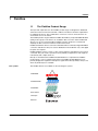
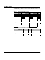


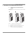
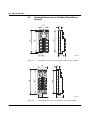
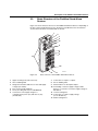
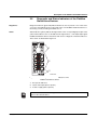

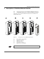
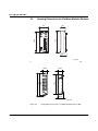
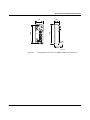
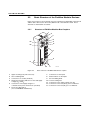
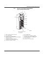
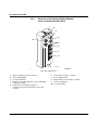
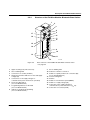
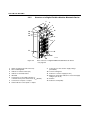
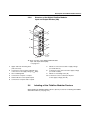
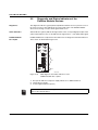
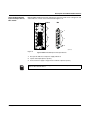
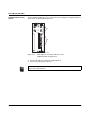
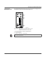
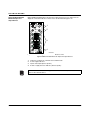
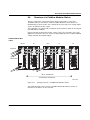
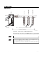
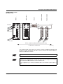
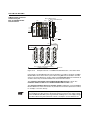
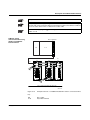
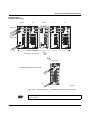
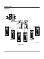


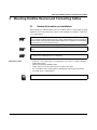
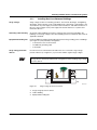
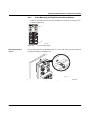
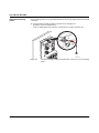
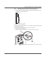
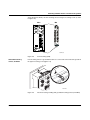
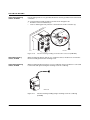
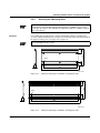
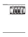
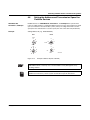
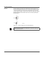
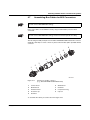
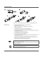
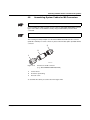
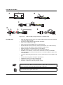
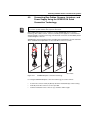
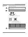
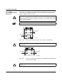
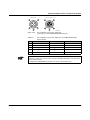
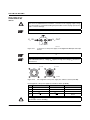
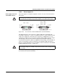
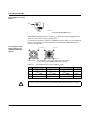
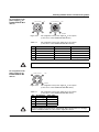
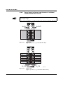
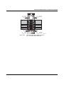
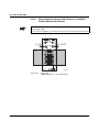
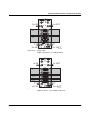
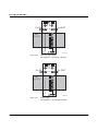
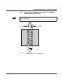
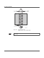
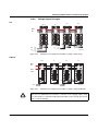
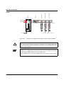
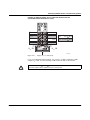
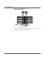
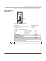
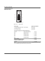
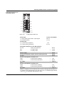
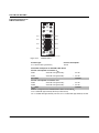
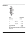
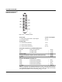
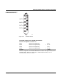
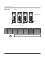
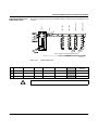
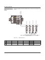
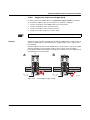


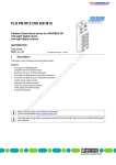
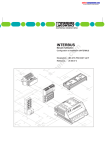
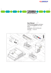


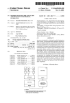
![FLM integration rod replacement + adjustment [v00]](http://vs1.manualzilla.com/store/data/005734078_1-ffddbeaec5f2fd08f6ea79cefb7ee063-150x150.png)
![FLM HD18 [v08]](http://vs1.manualzilla.com/store/data/005664321_1-9e0d84f2b9cac33a4ebfb5904f0dafa1-150x150.png)