1
Engineer Manual
Agility 3 Installer Manual
Important Notice
This guide is delivered subject to the following conditions and restrictions:
This guide contains proprietary information belonging to RISCO Group. Such
information is supplied solely for the purpose of assisting explicitly and properly
authorized users of the system.
No part of its contents may be used for any other purpose, disclosed to any person
or firm, or reproduced by any means, electronic or mechanical, without the express
prior written permission of RISCO Group.
The information contained herein is for the purpose of illustration and reference
only.
Information in this document is subject to change without notice.
Corporate and individual names and data used in examples herein belong to their
respective owners.
Compliance Statement
Hereby, RISCO Group declares that the Agility series of central units and accessories are
designed to comply with:
EN50131-1, EN50131-3 Grade 2
EN50130-5 Environmental class II
EN50131-6 Type A
EN50136-1-1 and EN50136-2-1:
ATS5 for IP/GPRS; ATS2 for PSTN
Signaling Security: - Substitution security S2
- Information security I3
For more information refer to App. E
UK: DD243:2004, PD 6662:2004, ACPO (Police)
USA: FCC: Part 15B, FCC part 68
CANADA: CS-03, DC-01
All rights reserved.
2013 RISCO Group
April 2013
Page ii
Agility 3 Installer Manual
Table of Contents
CHAPTER 1 INTRODUCTION .................................................................................. 1
ARCHITECTURE ............................................................................................................ 2
MAIN FEATURES .......................................................................................................... 3
AGILITY 3 COMMUNICATION METHODS ........................................................................ 4
TECHNICAL SPECIFICATIONS......................................................................................... 6
CHAPTER 2 INSTALLING THE AGILITY 3............................................................ 7
AGILITY MAIN COMPONENTS ....................................................................................... 7
COMMUNICATION MODULES ........................................................................................ 8
MOUNTING THE AGILITY ............................................................................................ 10
CHAPTER 3 ENGINEER PROGRAMMING ........................................................... 22
PROGRAMMING METHODS .......................................................................................... 22
WIRELESS DEVICE ALLOCATION ................................................................................. 25
DELETING WIRELESS ACCESSORIES ............................................................................ 28
ESTABLISH COMMUNICATION TO THE CLOUD SERVER ................................................. 29
PIR CAMERA ............................................................................................................. 31
CHAPTER 4 ENGINEER MENUS ............................................................................ 32
USING THE AGILITY KEYPAD KEYS .............................................................................. 32
ACCESSING THE ENGINEER MENUS ............................................................................. 32
PROGRAMMING MENU ................................................................................................ 33
TESTING MENU ......................................................................................................... 108
ACTIVITIES MENU .................................................................................................... 113
FOLLOW ME MENU .................................................................................................. 114
CLOCK MENU .......................................................................................................... 114
EVENT LOG MENU ................................................................................................... 115
MACRO MENU ......................................................................................................... 115
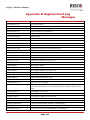
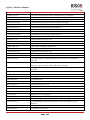
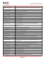
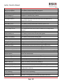
APPENDIX A REPORT CODES ............................................................................. 117
APPENDIX B ENGINEER EVENT LOG MESSAGES .......................................... 122
APPENDIX C LIBRARY VOICE MESSAGES ...................................................... 127
APPENDIX D REMOTE FIRMWARE UPGRADE ............................................... 129
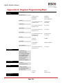
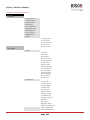
APPENDIX E ENGINEER PROGRAMMING MAPS ........................................... 134
APPENDIX F EN 50131 AND EN 50136 COMPLIANCE ...................................... 143
APPENDIX G SIA CP-01 COMPLIANCE .............................................................. 146
Page iii
Agility 3 Installer Manual
Chapter 1 Introduction
Agility 3 — RISCO Group's Picture Perfect Wireless Security Solution elegantly combines
state-of-the-art video verification and Smartphone apps with advanced wireless security
and safety features. Alarm Receiving Centres can now identify false alarms, as video
verification enables immediate confirmation of a crime-in-progress, prioritizing response,
increasing efficiency, and giving you on-the-go control and monitoring of your home
security.
Connecting the system to the RISCO Cloud server enables users to benefit from the
smartphone app and the self-monitoring feature as well as the capability to control their
alarm systems remotely. Additional advantages include the ability to set and unset the
system via the app, and usage of the visual verification feature with the additional
purchase of PIR camera detectors.
Featuring remote management, advanced communication, simple installation, and a
comprehensive range of peripherals, Agility 3 with video verification is the ideal wireless
solution for your residential and small commercial requirements.
Key Benefits:
Flexible Plug-in Communication
IP Module
GSM/GPRS Module
Fast PSTN Module
Use any single module, any combination or all three modules for backup, or no
communication for audible-only installations
2-Way Wireless Keypad with full programming capability
2-Way 8 button Wireless Remote Control with code protection, key-lock and
system status request and indication
2-way voice communication
Easy enrolling of Wireless Devices without a keypad
Remote enrolling according to Device ID
Combine one–way or two-way transmitters in the same system
Flash memory for easy firmware upgrade
Simple physical installation with wall brackets
Separate main panel, can be hidden for higher security
Program Transfer Module (PTM) for program backup
Simplified menu logic (only menus of installed devices are displayed, only
menus according to the authorization code are displayed)
Full voice-guided menu for remote system operation
Page 1
Agility 3 Installer Manual
Key Features:
32 wireless zones
3 partitions
Up to 3 bi-directional wireless keypads
Up to 8 rolling code keyfobs
Input/Output module:
2-way wireless communication to the Agility
Local transformer with rechargeable backup batteries
4 wired zones with selectable EOL resistance & 4 outputs (2x3A relay and 2x500mA)
Includes X-10 connection port
32 user codes + Grand Master Code
250 event log
Uses regular Sealed Lead Acid Battery 6V 3.2Ah
16 Follow Me destinations
2-way listen-in and talk with VOX
Dynamic language choice: Voice (minimum. 5), Text (minimum. 8)
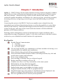
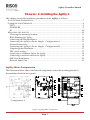
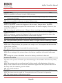
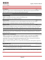
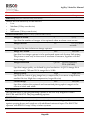
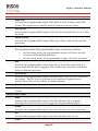
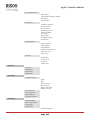
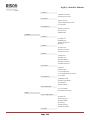
Architecture
The following diagram provides an overview of the Agility 3's architecture and
capabilities. Examine the figure before beginning with your Agility 3 installation to obtain
an overall picture of the full extent of the Agility 3 system capabilities.
Page 2
Agility 3 Installer Manual
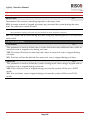
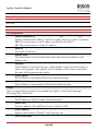
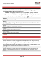
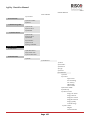
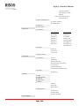
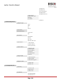
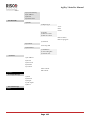
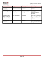
Main Features
The following table describes the main features of the Agility 3:
Detectors
32 Wireless zones:
4 Wired zones via
optional Wireless I/O
Expander
Total zones: 36
More than 25 zone
types
Full zone supervision
2-way and 1-way
detectors combined on
the same system
Image capture and
transmission via PIR
camera
Alarm Receiving Centre
Remote programming,
diagnostics and
communication test.
Report to 3 ARC.
Report through PSTN,
GSM, GPRS or IP.
ARC polling through IP
network.
Account number for
each ARC.
Flexible split reporting
for backup.
Call Save mode for nonurgent reports.
Remote device
enrollment.
Communication
Flexible communication
over GSM/GPRS, IP or
PSTN.
Backup capability
between the
communication methods.
Supports major reporting
formats.
Add on module for each
communication type.
Cloud Support
Engineer Programming
Local /Remote using
configuration software
Program transfer
module.
Full programming using
bi-directional wireless
keypad.
Flexible device
enrollment by serial ID
serial number or by RF
allocation.
Keypad programming
menu adjusted to
existing hardware.
Bi-directional Keypad
Fully Wireless
LCD display
S.O.S / Two way
communication
emergency key
Double tamper
protection (Box &
Wall)
2-Way Wireless Slim
Keypad Reader
User Operating Tools
Bi-directional 8 button
key fob
Bi-directional Keypad
4 button keyfob
Remote phone operation
SMS
Configuration software
Web browser
Smartphone App for
self-monitoring
Codes:
1 engineer code
1 sub engineer code
1 grand master code
32 user codes
4 authority levels
Optional 4 or 6 digits
code definition
Home Automation
4 outputs via wireless I/O
expander
16 X-10 outputs via
wireless I/O expander
Outputs can follow
system, partition, zone or
user events
Outputs can be
scheduled, or activated
automatically, or by user
command (SMS, web
browser, app or remote
phone)
Follow Me:
16 follow me
destinations
Follow me can be
defined as voice
message, SMS, Email
or to smartphones
User control over the
system
Security code
protection
Unlimited email
destinations from the
Cloud server
Visual Verification
Up to 8 eyeWave™
PIR cameras
Smartphone/Web
access
False alarm reduction
Sirens
Built-in sounder
Fully wireless external
and internal wireless
sirens
Up to 3 Wireless
Sounders
Voice capabilities
2-Way communication
Remote phone operation
Full voice menu guide
System event messaging
Local announcement
messages
Voice description for
zones, partitions, etc.
Wireless Features
Signal jamming
indication
Receiver calibration
868MHz radio frequency
Programmable
supervision time
Tamper detection in
transmitters
Low battery detection in
transmitters
Page 3
False Alarm Reduction
Swinger shutdown
Zone crossing
Report delay to ARC
Abort alarm feature
Soak test
Final exit zone
Agility 3 Installer Manual
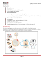
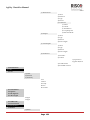
Agility 3 Communication Methods
Traditional
Agility can communicate information to Alarm Receiving Centres or to home owners
(Follow Me) through various communication channels, depending on the physical
communication module installed inside the panel. Communication can be established
through PSTN or GSM/GPRS.
All methods can be used for:
Reporting events to Alarm Receiving Centres
Sending automatic notifications to the owner
Remote system programming and maintenance
Owner remote control
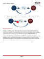
Cloud Communication
Agility 3 can be constantly connected to a dedicated application server using IP or GPRS.
The cloud server handles all communication between the Agility, Alarm Receiving Centres
and web users enabling monitoring and control to be performed via the web.
Cloud servers offer enhanced functionality:
Video verification for Alarm Receiving Centres and end-users
Use of smartphone applications
Use of web application to monitor and control the Agility from any location
Cloud communication can be defined as either of the following:
1. Parallel communication: Reports can be sent in parallel through the cloud or
straight from Agility to Alarm Receiving Centres/user. Parallel report is defined
by the type of installed communication module in the panel.
Page 4
Agility 3 Installer Manual
2.
Back up mode communication :Cloud as main route. If the cloud fails, Agility
moves to back up communication, depending on installed modules
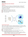
Video Verification
Agility™ 3 supports visual verification with a self-monitoring smartphone app (also
available via web browser) which enables homeowners to control their alarm systems
remotely as well as view real-time images taken inside their premises with the eyeWave™
wireless PIR camera detector which communicates with the RISCO Cloud server.
In the event of an alarm, the PIR camera is automatically activated and captures a
sequence of images which it sends to users via RISCO's smartphone/web application. This
capability enables users to view the images and confirm if there is a crime in progress.
Alarm Receiving Centres can also benefit from this feature as the capability to ascertain
whether there is a false alarm will save them valuable time and resources
Page 5
Agility 3 Installer Manual
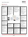
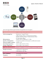
Technical Specifications
The following technical specifications are applicable for the Agility:
Electrical Characteristics
Power
230VAC (-15%+10%), 50Hz, 50mA
Units consumptions
Backup battery
Main board: Typical 130mA
GSM: Stand by 35mA, Communication 300mA
Modem: Stand by 20mA, Communication 60mA
IP Card: 90mA (Max)
Sealed Lead Acid Battery 6V 3.2Ah
Speaker Configuration
External in parallel with internal or additional external
Internal Sounder intensity
90 dBA @1m
Operating temperature
-10°C to 40°C (14°F to 131°F)
Storage temperature
-20°C to 60°C (-4°F to 140°F)
Physical Characteristics
Dimension
Weight (no battery)
268.5 mm x 219.5 mm x 64 mm (10.57 x 8.64 x 2.52 inch)
1.31Kg (Full configuration)
GSM module: 0.045 Kg
Wireless Characteristics
Radio Immunity
According to EN 50130-4
Frequency
868.65 MHz
Page 6
Agility 3 Installer Manual
Chapter 2 Installing the Agility 3
This chapter covers the installation procedures of the Agility, as follows:
AGILITY MAIN COMPONENTS ....................................................................................... 7
COMMUNICATION MODULES ........................................................................................ 8
PSTN ....................................................................................................................... 8
GSM/GPRS .............................................................................................................. 9
IP........................................................................................................................... 10
MOUNTING THE AGILITY ............................................................................................ 10
Choosing the mounting location ............................................................................. 11
Wall Mounting the Agility....................................................................................... 11
Connecting the Backup Battery............................................................................... 14
Connecting the Agility to Power Supply - Configuration A ...................................... 15
Ground Connection ................................................................................................ 15
Connecting the Agility to Power Supply - Configuration B ...................................... 16
Completing the Installation .................................................................................... 17
DIP switch setting .................................................................................................. 17
Connecting a telephone line to the Agility ............................................................... 18
Connecting a network cable to the Agility ............................................................... 19
SIM Card Installation............................................................................................. 20
External Audio Unit ............................................................................................... 21
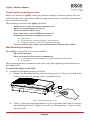
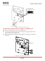
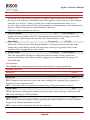
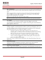
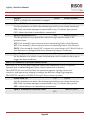
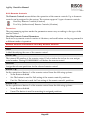
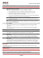
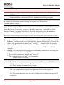
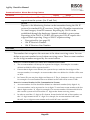
Agility Main Components
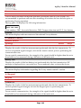
The illustration below shows the internal components (when the mounting bracket is
disassembled from the back panel).
8
OPEN
9
LOCK
22
10
18
33
11
1
ON
1
2
3
4
44
1
12
5
6
7
5
17
13
14
16
Configuration A
Configuration B
Figure 1: Agility Main Components
Page 7
15
Agility 3 Installer Manual
1. Installation Bracket
7.
PSU
13 RS 232 communication connector
2. Telephone terminal blocks
8.
Back Panel
14. Battery compartment
3. Audio Unit terminals
9.
SIM Card socket
15. Battery compartment cover
4. Ribbon flat cable jack
10. Ribbon flat cable
16. Battery fling leads
5. AC connection terminals/DC Socket
11. DIP Switches
17. Tamper switch
6.
12 PTM connector
18. IP Card network connector
Communication Modules
PSTN
The Agility PSTN modem is an easy-to-add plug-in modem that enables an inexpensive
PSTN connection, for use as either the primary communication channel or as a failure
back-up channel to the cloud connection, or GSM/GPRS or IP communication. The PSTN
modem enables the panel to communicate with a central station (ARC) using common
format protocols (SIA, Contact ID).
Page 8
Agility 3 Installer Manual
GSM/GPRS
The Agility™ GSM/GPRS module is an easy-to-add plug-in module that enables the
system to communicate over GPRS/GSM networks for reporting, control and
programming. It can be used as the primary communication channel or as a failure back up
for the IP or PSTN communications.
Reporting events to Alarm Receiving Centres can be done over voice, SMS or GPRS using
the RISCO IP Receiver. Events can be reported in SIA/IP, SIA and Contact ID monitoring
protocols.
Using GPRS connectivity, the Agility™ system can be constantly connected to the RISCO
Cloud enabling visual verification and control using the smartphone application, DTMF, or
SMS. In addition, users can enjoy peace of mind by receiving real time messages from the
RISCO Cloud as well as SMS, voice message and email alerts.
The GSM/GPRS module also supports two- way voice communication which has been
found to be beneficial for elderly care, allowing two way communication with users in
times of emergency
Page 9
Agility 3 Installer Manual
IP
The Agility IP module is an easy-to-add plug-in module that enables system
communication over a TCP/IP network. The plug-in IP Module can be used as the primary
communication channel or as the failure back-up channel to GSM/GPRS or PSTN
networks. Using the IP module, the Agility system can be connected to the RISCO Cloud
server, allowing both real time event reporting and end user RISCO advanced smart phone
applications. The IP module employs common format protocols (SIA, Contact ID) to send
alerts to Alarm Receiving Centres using the RISCO IP Receiver. In addition, the Agility can
send events in SIA IP protocol over TCP/IP to Alarm Receiving Centres that have standard
IP receivers. For end users, the IP module enables sending email alerts and system status
information. The IP module enables remote programming of the panel using the
configuration software over an IP/PSTN line.
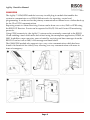
Mounting the Agility
IMPORTANT: As the Agility has no user-replaceable parts (for instance: power cord, fuse, battery,),
only certified engineers are allowed to replace faulty parts.
Page 10
Agility 3 Installer Manual
Choosing the mounting location
Before you mount the Agility, study the premises carefully in order to choose the exact
location of the unit for the best possible coverage and yet easily accessible to prospective
users of the alarm system.
The mounting location of the Agility should be:
CENTRALLY LOCATED AMONG THE TRANSMITTERS.
NEAR AN UNINTERRUPTED AC OUTLET.
NEAR A TELEPHONE (IP) OUTLET.
IN AN AREA WITH A GOOD GSM RECEPTION LEVEL
FAR FROM SOURCES OF INTERFERENCE, SUCH AS:
Direct heat
Electrical noise such as computers, televisions etc.
Large metal objects, which may shield the antenna.
IN A PLACE WHERE THE ALARM CAN BE HEARD DURING PART SETTING MODE.
Wall Mounting the Agility
The Agility is comprised of two sub-assemblies:
MOUNTING BRACKET
MAIN UNIT WHICH IN ITS TURN IS COMPRISED OF:
Front panel (not disassembled on a regular installation procedure)
Back panel
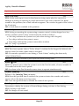
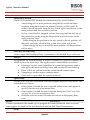
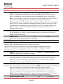
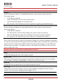
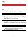
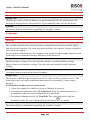
The mounting bracket is mounted on the wall, using the supplied proper hardware, as
described below:
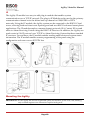
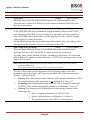
To mount the Agility on the Wall:
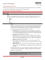
1.
Separate the Mounting bracket as follows:
a. Release the Mounting bracket captive locking screws (1, Figure 2) located at the
bottom of the unit, by turning screws counterclockwise.
1
Figure 2: Mounting Bracket screws
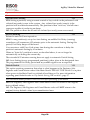
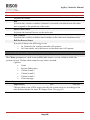
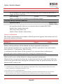
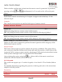
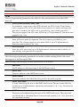
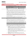
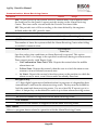
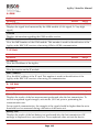
b. Gently, pull up the mounting bracket to a 45° angle and slide it down to release
the mounting bracket (2, Figure 3) from the two locking tabs (1, Figure 3) at the
top of the unit.
Page 11
Agility 3 Installer Manual
Note: Do not open the Mounting bracket to a larger angle in order not to break the two top tabs and not to
tear up the ribbon flat cable connecting the power supply unit to the front panel (PCB).
c.
Disconnect the ribbon flat cable (3) from the power supply unit while leaving it
connected to the Main panel.
1
3
2
Figure 3: Mounting Bracket removal
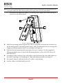
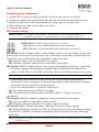
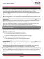
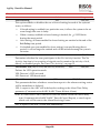
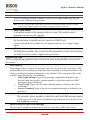
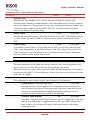
2.
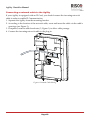
Hold the mounting bracket against the wall as a template and mark the locations for
the mounting holes (5 mounting holes item 1, and an additional hole for securing the
tamper protection bracket item 2, are available, see Figure 4).
3.
Drill the desired mounting holes and place the screw anchors. Use the supplied 5
Philips pan head screws to attach the Mounting bracket to the wall (ST4.2 mm x 32
mm DIN 7981).
4.
According to the location of the wall cables, route and insert the wires and cables via
the cable’s openings (3) (including AC cable and telephone cable), see figure 3.
5.
If required, remove cable knockouts (5) to allow wire passage.
6.
Anchor cables with dedicated hooks (4).
Page 12
Agility 3 Installer Manual
1
1
4
4
3
3
3
3
2
2
1
1
Configuration B
Configuration A
5
6
7
Figure 4: Wall Installation
7.
Adjust the Tamper switch (using a flat screwdriver) according to your preferred
configuration.
a. Box and Wall configuration (see Figure 4, detail 6) - Triggers the tamper when the
box or the wall mounting are tampered.
b. Box only configuration (see Figure 4, detail 7) – Triggers the tamper when the box
is tampered.
Page 13
Agility 3 Installer Manual
Connecting the Backup Battery
The Agility has a safety approved, sealed lead acid 6V, 3.2Ah rechargeable backup battery
for use in case of a main power failure:
Note: The battery is supplied with the Agility.
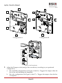
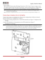
To insert the backup battery:
Remove the battery compartment cover screw (see Figure 5, 3) located at the top of the
cover by turning the screw counter clockwise and pulling the Agility battery cover
outward.
1
2
3
2
Figure 5: Battery Compartment
a. Insert the battery into its place and connect the flying leads to the battery
according to the correct polarity (Red +) (Black -).
b. Return the battery compartment cover (after placing the battery in) and secure
with locking screw.
Note: The Agility Rechargeable battery should be charged for at least 24 hours.
CAUTION: Risk of explosion if battery is replaced by an incorrect type. Dispose of used batteries according
to the instructions..
Page 14
Agility 3 Installer Manual
Connecting the Agility to Power Supply - Configuration A
Note: The Agility panel is permanently connected to the mains. The connection must be made according to
your country's local regulations. As a general guideline, connect the Live Neutral and Ground using a
safety approved 3-wire 18AWG power cable (14-mm minimum diameter flexible PVC cable which
complies with IEC60227). The cable should be brought to the Agility panel in a protective plastic
conduit (diameter - 16mm minimum).
A 2-pole 16A circuit breaker and earth leakage protector should be used to disconnect the live
conductor, and should be provided as part of the building installation.
The Agility is powered by a safety approved 230VAC.
1. Remove the power supply unit cover (Figure 6, 1).
2. Connect the power wire (Safety approved, SVT, 18AWG, 0.75mm2) to the
power terminal located on the power supply unit (TB1) (2, Figure 6).
Note: The power wire is not supplied with the Agility.
3. DO NOT connect the cable to the wall power supply at this point.
Ground Connection
Important: This equipment must be connected to a Protective earthling terminal in the building
installation. Use a min 18A WG yellow/green conductor for this connection.
Grounding provides a degree of protection against lightning and induced transients for
any piece of electronic equipment that may, due to lightning or static discharge,
experience permanent or general malfunctions. The ideal ground is considered to be a
unified earth ground in which an 8-foot copper-clad rod, located close to the existing
power and telephone ground rods, is sunk several feet into the earth. Appropriate
hardware and clamps are then used to electrically connect each of these rods together and
then to the ground terminal of the device to be protected.
It may be possible to use an existing electrical ground on the premises if one is close
enough to the Agility. When connecting the ground wire, use a solid 14-gauge wire [or
larger (numerically lower) size]. Keep this wire as short as possible and do not run it in
conduit, coil it, bend it sharply, or run it alongside other wiring. If you must bend it or
change its direction, it should have a radius of at least 8 inches at the point from which it is
bent. If in doubt, you may want to enlist the help of a licensed electrician in matters
concerning such grounding.
To connect to ground (Earth):
Connect between the Agility’s ground terminal and an acceptable electrical ground
connection for the lightning transient protective devices in this product to be effective.
Important: Connecting to ground must be performed according to the local National Electrical Code.
Page 15
Agility 3 Installer Manual
N ~
Figure 6: Connecting AC Power wires
Connecting the Agility to Power Supply - Configuration B
The Agility is powered by a 9VDC/1.0A Transformer.
8.
Connect the transformer power jack to the power supply located on the
power supply card (1, Figure 6A).
9.
DO NOT connect the transformer inlet cable to the wall power supply at
this point.
From 9VDC/1.0A
Transformer
1
2
Figure 6A: Connecting DC Power Cable
Page 16
Agility 3 Installer Manual
Completing the Installation
1. Set the DIP switches according to the DIP Switch Setting section (see below).
2. Connect the ribbon flat cable between the main panel and the mounting bracket (J1).
3. Mount the Main unit to the mounting bracket using captive locking screws.
4. Plug in the power cable to the wall power outlet.
5. Power up the Agility.
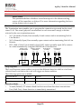
DIP switch setting
Important Notice: As of Agility 3, DIP switches 1–4 in previous versions have been shifted to 2–5,
respectively. DIP switch 1 is used for the new Z-wave capability (future use).
DIP Switch 1: Z-Wave: (Requires RISCO Z-wave module)
ON: Agility Z-wave communication protocol activated
OFF: (Default): Z-wave communication protocol is not active.
DIP Switch 2 (E-A): External Audio: Used to define if the voice of the Agility will go from
the main unit or from an External Audio Unit. When the external unit is connected to the
Agility the voice will be heard only through the Audio voice unit.
ON: External Audio Unit is connected to the Agility
OFF (Default): External Audio unit not connected to the Agility.
DIP Switch 3 (DFLT): Default jumper: Used when performing the following 3 operations:
1. To return engineer, sub-engineer and grand master codes to their default factory
values. Set this DIP switch to ON, disconnect all power and then reconnect the power.
Note: Code Length does not change.
2. To manually erase wireless devices. Set this DIP switch to ON while power is
connected. Execute a long press on the main unit button until a beep (indicating that
all wireless devices have been erased) is heard.
3. To save or transfer data to or from the PTM device.
ON: To transfer data from the PTM to the panel.
OFF: To transfer data from the panel to the PTM. (Refer to Chapter 3 for these
procedures.)
DIP Switch 4 (PRGM): Enables loading local software updates to the Agility
ON: software updates to the Agility can be loaded
OFF (Default): software updates to the Agility cannot be loaded
DIP Switch 5 (BAT): Defines the Battery Discharge Protection option settings
ON: Battery Discharge Protection is OFF: The battery may be totally discharged during
continuous AC failure, thus battery replacement may be required (no deep discharge
protection).
Note: In this position the Agility will start to operate from a battery power supply whether it is connected
to the Mains or not.
Page 17
Agility 3 Installer Manual
OFF (Default): Battery deep Discharge Protection is ON: If an AC power outage occurs,
the Agility automatically disconnects the battery when its backup battery voltage drops
below 5.8 VDC, in order to prevent "deep discharge” that may damage the battery.
Note: In this position the Agility will not start to operate from a battery power supply, unless
connected to the Mains first.
Note: If the battery voltage drops below 5.8 V or it is not connected, its keypad menu reading is “0.0”.
Connecting a telephone line to the Agility
Connect the system to a telephone line if the system configuration includes an internal
modem (identical for Configuration A and B).
Connect the incoming telephone line to the LINE terminals (see Figure 7: Telephone Line
Wiring).
Connect any telephone on the premises to the SET terminals (see Figure 7:
Telephone Line Wiring).
NOTE: To ensure line seizure capability, and comply with FCC part 68 regulations, the equipment must be
connected directly to the Phone company lines ('CO'). Whether connected via RJ11, RJ31, the line port
must be connected to the CO lines without any other phones or other telecom equipment between
them. Other telecom equipment can be connected only after (in series) the alarm panel.
Figure 7: Telephone Line Wiring
Page 18
Agility 3 Installer Manual
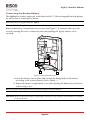
Connecting a network cable to the Agility
If your Agility is equipped with an IP Card, you should connect the incoming network
cable in order to enable IP Communication.
1. Separate the Agility from the mounting bracket.
2. According to the location of the network cable, route and insert the cable via the cable’s
openings (see Figure 3).
3. If required, remove cable knockouts (5, Figure 3) to allow cable passage.
4. Connect the incoming network cable to the plug-in.
Figure 8: Network Cable Wiring
Page 19
Agility 3 Installer Manual
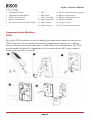
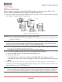
SIM Card Installation
If your Agility is equipped with a GSM/GPRS module, you should insert a SIM card in
order to enable communication through the GSM/GPRS network.
Insert the SIM into the dedicated SIM card slot located on the rear side of the back panel
(See Figure 1: Agility Main Components).
LOCK
LOCK
2. Open the SIM card
hatch. Insert SIM card
into dedicated slot.
OPEN
1. Slide down SIM
card hatch .
OPEN
OPEN
LOCK
SIM Card
3. Close the SIM card
hatch . Slide up to lock.
Figure 9: SIM Card Insertion
Important: Do not install SIM card while power is applied to the Agility.
Do not touch SIM Card connectors! If doing so, you may release an electrical discharge that could
damage the SIM card.
If a PIN code is required for the SIM card, the Agility will indicate a PIN code fault.
To fix the fault, and thus enable the SIM card to operate properly, enter the PIN code
number, located in the Communication > GSM parameters menu.
Note: Ensure that you have the PIN code. Be aware that after three wrong attempts (recognized by the SIM
card) to enter a PIN number, the SIM card will lock.
You will have to contact your local cellular provider to unlock the SIM card.
If you want to disable the SIM PIN code you should follow the steps:
a. Insert the SIM card into a standard GSM mobile phone.
b. Insert the PIN code.
c. Access the phone security menu and selecting PIN OFF. Once done, re-test by
switching the phone OFF, then switching ON. The PIN code should not be requested
again.
Once the SIM card is inserted it is recommended to test the operation of the SIM by
conducting a call and testing the GSM signal strength. For more information refer to the
programming menus of the GSM menu.
Note: In some countries an SMS center phone number might be required in order to enable SMS messaging.
This phone number is provided by the provider. Programming the SMS center phone into the SIM can
be done using a standard GSM mobile phone or from the Agility keypad or configuration software.
Page 20
Agility 3 Installer Manual
External Audio Unit
The Agility enables to connect a remote external Audio Unit instead of the main internal
unit in order to listen to the system's audio messages. In addition the unit enables you to
talk into your premises.
To connect the Audio unit:
1. Wire the Audio unit to the Agility as displayed in the Wiring Diagram described
in Figure 10. The terminals for wiring the Audio Unit to the Agility are located on
mounting bracket.
2. Set DIP Switch 2 (E- A) (External Audio) to On position.
Audio Unit Terminals on
the Mounting Bracket
AUX GND TMP
External Audio Unit
MIC SPKR
IN
OUT AUX COM TMP
LED
AUDIO
RED BLK
Figure 10: Wiring the External Audio Unit to Agility
Page 21
Agility 3 Installer Manual
Chapter 3 Engineer Programming
Programming Methods
There are 4 available options for programming the Agility:
Configuration Software
Wireless Keypad
Engineer Keypad
PTM
Configuration Software
A software application that enables you to program the Agility from a PC computer. It
offers the following alternatives:
Working locally, through a portable computer connected to the Agility via cable
Working at a remote site, communicating with the Agility via a phone line,
modem or IP address.
For further information on programming the Agility via the Configuration software, refer
to the Configuration Software manual.
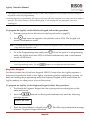
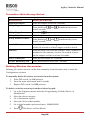
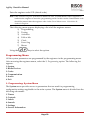
Wireless Keypad–Initial Default Language Specification
The Agility can be fully configured via the wireless keypad.
New systems require a default language specification before any further configuration.
System language specification through “enrollment” (see below) of new system initial
keypad is performed as follows:
To define the keypad and system language:
1. After the Agility is connected to the power supply press the button on the main
unit for 5 seconds. The unit beeps once and enters “Learn” mode. The LEDs light
up one after the other.
2. Send an RF signal “write message” from the 2-way LCD keypad by pressing both
3.
keys
and
simultaneously for at least 2 seconds until a generic device
allocation message is broadcast and also displayed on the keypad.
In the displayed language menu, select the system language (and customer
default) settings and then press
Notes:
1. If the keypad lapses into sleep-mode before you have chosen the language, restore the choosesystem-language display through simultaneously holding [*] and [9])
Page 22
Agility 3 Installer Manual
2. The Agility can be programmed via any of the 2 way keypads in your system, but only using one
keypad at a time for programming.
3. During engineer programming, the keypad will turn off after 4 minutes if no entry has been made to
the keys. Press any button to restore the keypad. It will display the last parameter you were
working on.
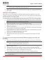
To program the Agility via the Wireless Keypad, follow this procedure:
1.
Perform system device allocation for the keypad (refer to page 25).
2.
Press
and enter the engineer code (default code is 0132). The keypad will
sound a confirmation sound.
Note: If a Grand Master code is required to confirm the engineer code, it should be entered at this
stage after the engineer code.
3.
Go to the Programming menu and press
. Once the panel is in programming
mode, the Agility main unit LEDs will flash simultaneously and a confirmation
sound will be heard.
Note: The engineer can also program user activities by selecting the Activities menu instead of
the Programming menu. Use the
buttons to navigate between the menus.
Engineer Keypad
For those systems that do not have keypads, RISCO Group offers the Agility engineer a
temporary keypad to be used as any Agility wireless keypad for configuring a system. An
hour after exiting the programming mode the Engineer Keypad will be erased from the
Agility memory or when power is lost to the system.
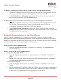
To program the Agility via the Engineer Keypad, follow this procedure:
1. To allocate the Engineer Keypad into the system perform a short press on the
main unit button.
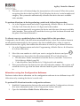
2.
Press the
message appears:
buttons on the keypad simultaneously until the following
Insert GM Code
3.
Enter the Grand Master code and press
is heard: “Engineer Keypad Allocated”.
Page 23
. The following confirmation message
Agility 3 Installer Manual
Note: When a wrong Grand Master code is entered, the keypad will be deleted. To continue
this procedure, perform reallocation of the keypad.
4.
Follow steps 2 and 3 of the wireless keypad (see page 22) to begin programming
the system.
PTM: Data Storing Device
The PTM is a tiny circuit board into which the Agility panel can transmit a copy of the
system's configuration. The PTM stores this copy and can also transmit the configuration
information back to the Agility panel.
To transfer the system configuration from the panel to the PTM, follow this procedure:
1. Disconnect the flat cable and remove the Agility main unit from its wall bracket.
Note: Make sure the battery is inserted into the main unit.
2.
3.
4.
5.
6.
7.
Make sure that DIP switch 3 is set to OFF (default setting).
Place the PTM onto the 5-pin PTM located on the rear of the main unit PCB. The
PTM LED will turn on.
Press the main unit button for 5 seconds. The PTM LED will flash quickly during
the transmission of information to the PTM.
Once transmission is complete, the panel will sound a confirmation beep and the
PTM LED will stop flashing and turn on steady.
Disconnect the PTM from the main unit.
Reconnect the flat cable to the main unit and replace the main unit in its wall
bracket.
To transfer the system configuration from the PTM to the Agility panel, follow this
procedure:
1. Disconnect the flat cable and remove the Agility main unit from its wall bracket.
Note: Make sure the battery is inserted into the main unit
Make sure that the Default Enable system flag is on
2.
3.
4.
5.
Set DIP switch 3 to ON.
Place the PTM onto the 5-pin PTM connector located on the main unit PCB.
All LEDS on the main unit will begin to flash simultaneously. The PTM LED will
flash during the transmission of information to the panel.
Once transmission is complete, the panel will sound a confirmation beep.
Note: If the procedure fails the panel will make 3 short error beeps, and you will need to do the
procedure again
Page 24
Agility 3 Installer Manual
6.
7.
8.
Disconnect the PTM from the main unit.
Reset DIP switch 3 to OFF.
Reconnect the flat cable to the main unit and replace the main unit in its wall
bracket.
Wireless Device Allocation
Each wireless device must identify itself to the system receiver. The following section
describes the different ways to allocate all of your devices to the system in order to later
configure each device's parameters.
The learning procedure between the wireless devices and the main unit can be performed
either from the main unit, a wireless keypad or via the Configuration Software.
Quick Allocation using the main unit button
To perform quick allocation using the main unit button, follow this procedure:
Note: To enable Quick Allocation mode the System bit "Quick Learn" should be enabled.
1.
Set the main unit to Learn mode with a long press on the main unit button. Each
LED will light up one after another.
Note: The unit will sound each time you enter or exit the Learn mode.
2.
3.
Send a transmission from each device (refer to the Transmitters write message
method table in section). The system will automatically identify each device
according to different categories (for example: detectors, sounders, keypads,
remote controls etc.) and enter each device and its default value into the unit's
memory. Each device receives an index number from the system.
Exit the Learn mode with a short press on the main unit button.
Allocation using the keypad
It is possible to perform allocation via the keypad in two different ways: RF Allocation or
by entering the device’s serial code.
To perform RF Allocation via the keypad, follow this procedure:
1. Go to the Engineer menu and select Programming Radio Device Allocation
1) RF Allocation. The system immediately goes into Learn mode.
2. Send a transmission from the device. (See table: Transmitters Write Message
Method, page 28)
Page 25
Agility 3 Installer Manual
3.
The main unit will acknowledge the transmission with a sound. When the system
recognizes the device the keypad LCD will display the device's serial number and
category. The system also automatically allocates the device the next available
index number.
To perform allocation via the keypad using a serial code, follow this procedure:
1. Go to the Engineer menu and select Programming Radio Device Allocation
2) By Code. Enter the device’s 11 digit serial code number.
2. The system automatically recognizes the device and allocates it the next available
index number. The system will sound the device type that has been allocated and
the place it has been allocated to.
To allocate zones to a predefined place via the keypad follow this procedure:
Compared to the RF and Code allocations mentioned before, where the wireless elements
are allocated automatically by the system to the first available place, when it comes to
zones allocation the Agility also enables the allocation of zones to a pre-defined location.
1. Go to the Engineer menu and select Programming Radio Device Allocation
3) Zone Allocation.
2.
3.
4.
Select the zone number to which you want to assign the detector and press
.
Using the arrow keys select the allocation method: RF or Code allocation.
RF allocation: Send a transmission from the device. (See table: Transmitters
Write Message Method, page 28)
Code allocation: Enter the device’s 11 digit serial code number.
The system allocates the detector into the selected index number. The system will
sound the device type that has been allocated and the place it has been allocated
to.
Allocation using the Configuration Software
Perform wireless device allocation via the configuration software in two different ways: RF
Allocation or by entering the device’s serial code.
To perform RF allocation from the configuration software
1. Establish Communication between the main unit and the Configuration software.
(For more information refer to the Configuration Software Manual)
2. Open the Activities > Radio Device Allocation screen.
Page 26
Agility 3 Installer Manual
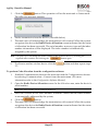
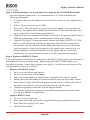
3.
Click the
button. This operation will set the main unit to Learn mode.
The following message appears:
4.
5.
Send a transmission from the device. (See table below)
The main unit will acknowledge the transmission with a sound. When the system
recognizes the device the Radio Device Allocation screen indicates that the status
of allocation has been successful. The serial number, accessory type and the index
number information will be displayed. The index number is automatically
assigned by the system.
Note: If required you can change the index number of the wireless device by selecting the
required index number and clicking the
6.
To allocate another wireless device click the
3-5.
button again.
button and then repeat steps
To perform Code allocation from the configuration software
1. Establish Communication between the main unit and the Configuration software
by selecting Communication > Connect from the main menu. (For more
information refer to the Configuration Software Manual)
2. Open the Radio Device Allocation screen. In the Allocation area, enter the device's
serial number.
Note: The serial number can be found on the device.
3.
Select the wireless device index number. Automatic means that the index number
is automatically addressed by the system,
4.
Click the
button.
The main unit will acknowledge the transmission with a sound. When the system
recognizes the device the Radio Device Allocation screen indicates that the status
of allocation has been successful.
5.
Page 27
Agility 3 Installer Manual
Transmitters Write Message Method
How to send a write message (transmission):
Wireless Device
Sending Write Message
Detector/Contacts
Press the tamper switch for 3 seconds
2-Way Keypad
Press both keys
least 2 seconds
and
simultaneously for at
1-Way Keypad
Press the
1-Way Key fob
Click the button for at least 2 seconds
2-Way Remote Control
Press both keys
least 2 seconds
Smoke Detector
Insert battery. Write message is send automatically
within 10 seconds or when Tamper switch is closed.
Sounder
Press the reset switch on the sounder. After a squawk is
sounded at the sounder you have 10 seconds to press
on the tamper switch for at least 3 seconds.
Gas, CO detectors
Press the test button for 3 seconds
2 Panic Button Key fob
Press both buttons for at least 7 seconds
key twice
and
simultaneously for at
Deleting Wireless Accessories
Deleting all wireless devices can be done manually (from the main unit) or from the
Configuration software.
To manually delete all wireless accessories from the system:
1. Place DIP switch 3 to ON position.
2. Press the main unit button until it sounds.
3. Replace DIP switch 3 to OFF position.
To delete a wireless accessory from the wireless keypad:
1. Go to the Engineer menus and select Programming Radio Device
Modification
2. Select the device category
3. Go to Parameters option.
4. Select the device index number
5. Go to Serial number option and enter: 000000000000.
6.
Press
. The device will be deleted
Page 28
Agility 3 Installer Manual
To delete a wireless accessory from the system via the Configuration software:
1. Establish Communication between the main unit and the Configuration software
(For more information refer to the Configuration Software Manual)
2. In the Radio Device Allocation screen in the Delete Accessories area enter the
device's serial code and click the Delete button.
To delete all wireless accessories from the system via the Configuration software:
1. Establish Communication between the main unit and the Configuration software
by selecting Communication>Connect from the main menu. (For more
information refer to the Configuration Software Manual)
2. In the Radio Device Allocation screen in the Delete Accessories area, click the
Delete All button. When all accessories have been deleted the screen will indicate
that deletion has been successful.
Establish Communication to the Cloud Server
Agility 3 can be configured to be continually connected to a server, enabling image
transmission and user smartphone applications. When connected to the server, the server
handles all communication between the system, service providers and web users, enabling
monitoring and control to be performed over the internet.
Step 1: Enable cloud communication:
1. From the Engineer menu select: 1) System > 2) Controls > 3) Communication >
Cloud Enable [Y]
Step 2: Set up GPRS or IP Communication
Connection Through GPRS
1. From the Engineer menu select : 4) Communication > 1) Method > 2) GSM > 2 >
GPRS
2. Define APN code, user name and password. This information must correspond
with that of the SIM card service provider.
Connection through IP
1. From the Engineer menu select : 4) Communication > 1) Method > 3) IP > 1) IP
Config
2. Defines whether the IP address, which the Agility refers to, is static or dynamic. If
Dynamic select [Y] and the system refers to an IP address provided by the DHCP.
If static select [N] and define all other parameters in the menu.
Page 29
Agility 3 Installer Manual
Step 3: Define parameters for cloud connection using the IP or GSM/GPRS module:
From the Engineer menu select : 4) Communication > 5) Cloud and define the
following parameters:
1. IP Address: The server IP address (riscocloud.com or that of your organization's
server)
2. IP Port: The server port is set to 33000.
3. Password — The password for server access as provided by your provider (if
required). This password should be identical to the CP Password defined in the
server under the Control Panel page definition.
4. Channel: Select the communication path for the cloud. The path can be IP Only or
GSM Only depending on the communication module in the Agility.
5. Controls: The Agility 3 supports parallel channel reporting (via PSTN, IP, GPRS
SMS, or voice) to both the alarm receiving centre and FM when connected in
cloud mode. Use this setting to decide if the panel reports events to the alarm
receiving centre or follow-me in parallel to the report to the cloud or only as a
backup when the communication between the Agility and the cloud is not
functioning. For more information refer to Cloud Communication, page 4.
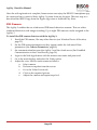
Step 4: Register with RISCO Cloud
If the Agility panel is defined to be connected to the RISCO Cloud, guide your customer to
self-register his system with the cloud. Registering with RISCO Cloud enables your
customer to monitor, control and configure your Agility 3 system from any location. The
self registration process is as follows:
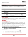
Register with RISCO Cloud
1. Go to www.riscocloud.com/register
2. Fill in your first name and last name
3. Enter your email address as Login Name (required for 1st time activation).
4. Define password (minimum of 6 characters and at least one digit) and confirm.
5. Enter in the 15 digits Panel ID as it appears on the sticker located on the side of
the panel or as printed on the postcard that arrived with the panel.
6. Complete registration form and click the Register button.
7. To complete registration, respond to the email message received on the email
account you defined as Login Name
Login to RISCO Cloud
1. Go to www.riscocloud.com.
2. Enter User Name and Password (as supplied during the registration process).
3. Enter Passcode (Agility User Code).
4. Click the Enter button.
Page 30
Agility 3 Installer Manual
Once the self registration is complete, homeowners can enjoy the iRISCO Smartphone app
for smart and easy control of their Agility 3 system from any location. The next step is to
download the iRISCO app from the Apple App store or Android Play Store.
PIR Camera
The Agility 3 enables the use of advanced PIR-based detection cameras. This use offers
combined detection with image recording. Up to eight PIR cameras can be assigned to the
Agility 3.
To install the PIR camera detectors with the Agility 3:
1. Enroll the PIR camera, like any other detector (see Wireless Device Allocation,
page 25)
2. Set the PIR camera parameters as they appear under the Advanced Zone
parameters (See Camera Parameters, page 60)
3. Set communication between the Agility 3 and the cloud server (See Establish
Communication to the Cloud Server, page 29)
4. Login to the Web Application with the master user name and password.
5. Go to the main display and select the Video option
6. Adjust the view field for each camera as follows:
a. Select camera
b. Perform a snapshot from the server.
c. Go to the Video Events tab.
d. Click on the required picture.
e. Adjust the camera and repeat steps b-d.
Page 31
Agility 3 Installer Manual
Chapter 4 Engineer Menus
The following chapter describes the parameters and programming options of the system
and radio devices. These parameters can be programmed via the Agility keypad or the
configuration software by the engineer.
Note: A note appears next to the parameters that can only be programmed via the configuration software.
For more information regarding the installation and use of the configuration software refer to the
Configuration Software manual.
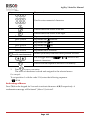
Using the Agility keypad keys
The Agility two-way keypad contains three LED indicators, an LCD display and a variety
of keys. The following table describes the typical uses of the keys when in programming
mode.
Keys
Description
The numerical keys on the keypad are used as quick keys, a
numerical sequence used as a shortcut to program an option.
To program the system using Quick keys:
1. Access the engineer menus (see below) and select the relevant main menu
option.
2. Click the quick keys in sequence to locate the parameter and press
.
Numerical keys are also used to input the numeric codes that may
be required for setting, unsetting, or used to activate specific
functions.
Exits from the current menu and returns to Normal Operation
mode
Terminates commands and confirms data to be stored
Used to browse through the menu: Scrolls up a list or moves the
cursor
Changes data
Accessing the Engineer Menus
To access the engineer menus via the Agility keypad, follow this procedure:
Press the
key to activate the keypad.
Page 32
Agility 3 Installer Manual
Enter the engineer code 0132 (default code).
Note: If the Authorize Engineer system bit is defined as YES, a Grand Master code is required to
authorize the engineer to enter the programming mode. In this case the Grand Master code
should be entered after the engineer code via the Grand Master menu Activities
Authorize Engineer.
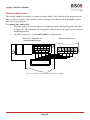
The following menu appears displaying a list of all the engineer menus:
1) Programming
2) Testing
3) Activities
4) Follow Me
5) Clock
6) Event Log
7) Macro
Using the
keys to select the options.
Programming Menu
All the system parameters are programmed by the engineer via the programming menu.
After accessing the engineer menus, select the 1) Programming option. The following list
appears:
1. System
2. Radio Devices
3. Codes
4. Communication
5. Audio
6. Exit
1. Programming: System Menu
The System menu provides access to parameters that are used for programming
configuration settings applicable to the entire system. The System menu is divided into the
following sub-menus:
1. Timers
2. Controls
3. Labels
4. Sounds
5. Settings
6. Service Information
Page 33
Agility 3 Installer Manual
7. Firmware Update
1.1 Timers
The Timers menu contains parameters that specify the duration of an action.
System: Timers
Parameter
Default
Range
Exit/Entry Delay 1
The amount of time before the system is set/unset. Usually used on front entrance door.
Entry Delay 1
30 sec
0-255 sec
45 sec
0-255 sec
Duration of entry delay 1 before the system is unset
Exit Delay 1
Duration of exit delay 1 before the system is set
Exit/Entry Delay 2
The amount of time before the system is set/unset. Usually used to back door.
Entry Delay 2
45 sec
0-255 sec
60 sec
0-255 sec
Duration of entry delay 2 before the system is unset
Exit Delay 2
Duration of exit delay 2 before the system is set
Bell Timeout
04 min 01-90 min
Duration of the sounder during alarm.
Bell Delay
00 min 00-90 min
The time delay before a sounder sound is produced after triggering an alarm.
AC Off Delay
30 min 0-255 min
In the case of a loss of AC power, this parameter specifies the delay period before
reporting the event or operating the Programmable Output. If the delay time is set to
zero, there will be no delay period.
Jamming Time
None
None, 10, 20 or 30 sec
Specifies the period of time that the system's receiver tolerates unwanted radio
frequencies capable of blocking (jamming) signals produced by the system's transmitters.
Once the specified time is reached, the system sends a report code to the alarm receiving
centre or activates a local sounder, depending on the Audible Jamming system control.
NONE: No jamming will be detected or reported.
Page 34
Agility 3 Installer Manual
System: Timers
Parameter
Default
RX Supervision
0 hours 0-7 hours
Range
Specifies how often the system expects to get a signal from the system's transmitters. If a
signal from a zone is not received during the specified time the zone will be regarded as
lost, the system will send a report code to the alarm receiving centre, and the system
status will be "Not Ready".
Notes: 0 hours disables supervision
It is recommended to set the supervision time to a minimum of 3 hours
TX Supervision
058
0-255 min
Specifies how often a bi-directional wireless device generates a supervision request to the
system.
If any of the accessories fail to transmit a supervision signal at least once, during the RX
Supervision time, the system will regard the accessory as Lost.
Note: The device will generate the supervision message according to the time defined.
Important: The RX Supervision time should be higher than the Tx Supervision time in order to eliminate
false lost event.
Redial Wait
30 sec
0-255 sec
The number of seconds between attempts at redialing the same phone number.
Applies to both the ARC Retries and FM Retries parameters.
Note: Used for both PSTN and GSM.
More
Swinger Limit Shutdown
00
0-15 times
A swinger is a repeated violation of the same zone, often resulting in a nuisance alarm
and usually due to a malfunction, an environmental problem, or the incorrect
installation of a detector or sensor.
This parameter specifies the number of violations of the same zone reported during a
single set period, before the zone is automatically omitted.
Note: 00 to disables the swinger shutdown
No activity
00
Page 35
0-99 hours
Agility 3 Installer Manual
System: Timers
Parameter
Default
Range
Determines the time limit for reception of signals from sensors used to monitor the
activity of sick, elderly or disabled people. If no signal is received from a zone defined
with the "No Activity" feature at least once within the defined time limit, a “noactivity” alert can be send to Follow Me destination, a local message can be heard and a
report to Monitoring Station can be defined to be send.
Options: 0 =this parameter is inactive.
Last Exit Sound
00
0-255 seconds
Defines the last seconds of the Exit Time that the beep sound will change (main unit
and keypads), indicating to the user that Exit Time is about to end.
Entry Omit
30 seconds
(15–240)
When the 2-Way Wireless Slim Keypad Reader is defined as Omit mode, this timer
defines the period during which an Open Delay zone type (typically door) can be
opened without triggering an alarm event.
Service Time
20 minutes
0-240 minutes
The time period that all tampers (main unit and accessories) can be opened for
purposes of battery replacement without triggering a tamper alarm. (See page 113,
Service Mode).
1.2 Controls
The Control menu contains parameters that control specific system operations.
System: Controls
Parameter
Default
Basic programming
Quick Set
YES
YES: Eliminates the need for a user code when setting (Full or partial) the system by a
keypad or 2-way remote control.
NO: A valid user code is required for setting using a keypad or remote control.
Allow Omit
YES
YES: Permits zone omitting by authorized system users after entering a valid user code.
NO: Zone omitting is NOT permitted.
Quick Status
YES
YES: A user code is not required before pressing the status key/button on your wireless
keypad or bi-directional remote control.
NO: A user code is required to activate the status key.
Page 36
Agility 3 Installer Manual
System: Controls
Parameter
Default
False Code Fault
YES
YES: A false code report is sent to the alarm receiving centre after five successive
attempts at setting or unsetting in which an incorrect user code is entered. No alarm
sounds at the premises, but a fault indication appears. The wireless keypad will be locked
for 30 minutes.
NO: A local alarm is sounded at the premises.
Sounder Squawk
YES
YES: Setting or unsetting the system using a remote control, wireless keypad or a keyswitch produces a brief "chirp" and activates the strobe as follows:
One chirp indicates the system is set (also when setting with a keypad).
Two chirps indicate the system is unset.
Four chirps indicate the system is unset after an alarm.
NO: No "chirp" is produced.
Audible Panic
NO
YES: The sirens operate when a "Police Alarm" is initiated at the keypad (if defined), the
remote control or when a panic zone is activated.
NO: No sounder operation occurs during a "Panic Alarm," making the alarm truly
"silent" (Silent Panic).
Note: The system always transmits a panic report to the alarm receiving centre.
Buzzer Bell
NO
YES: If an alarm occurs when the system is set in the Part Set mode, a buzzer sounds for
15 seconds before the sirens operate.
NO: An alarm in the Part Set mode causes sirens to operate simultaneously.
Audible Jamming
NO
Relates to the Jamming Time parameter.
YES: Once the specified time is reached, the system activates the sounder and sends a
report code to the alarm receiving centre.
NO: Once the specified time is reached the sirens do not operate.
Exit Beeps at Part
YES
Determines whether the system will sound beeps during exit time in Part Setting.
YES: Exit beeps will sound
NO: Exit beeps will not sound
Page 37
Agility 3 Installer Manual
System: Controls
Parameter
Default
Forced Device Setting
YES
YES: Setting a partition, using a remote control or key-switch can be performed with
violated (not ready) zones in the system. Any violated (not ready) zone(s) in the
partition will be omitted automatically. The partition is then "force set," and all intact
zones are capable of producing an alarm.
NO: The partition cannot be set until all violated (not ready) zones are secured.
Set Pre-warning
YES
Related to auto Set/Unset operation.
YES: For any partition(s) set up for Auto Setting, an audible Exit Delay (warning)
countdown will commence 4.25 minutes prior to the automatic Setting. During this
period, Exit Delay beeps will be heard.
You can enter a valid User Code at any time during the countdown to delay the
partition's automatic Setting by 45 minutes.
When an "Auto-Set" partition is unset, as described above, it can no longer be
automatically set during the current day.
The extended 4.25 minutes warning does not apply to automatic Partial Setting.
NO: Auto Setting for any programmed partition(s) takes place at the designated time.
The programmed Exit Delay period and any audible signal occur as expected.
Default Enable
YES
This option contains parameters that relate to what happens to the Engineer, SubEngineer and Grand Master codes if the Main Panel's DEFAULT DIP switch 3 is in place
when power to the Main Panel is switched off and then on. For more information
regarding panel defaults refer to: Dip Switch Setting, DIP switch 3, page 17.
Note: The Default Enable parameter’s state is not reset upon performing system default.
YES: The Engineer, Sub-Engineer and Grand Master codes will return to the original,
factory default values.
NO: The Engineer, Sub-Engineer and Grand Master codes will NOT return to the
original, factory default values by an unauthorized user.
Page 38
Agility 3 Installer Manual
System: Controls
Parameter
Default
Main Button: Status-Y/Talk-N
YES
The Agility enables the ARC to perform Listen-In and Talk functions in order to verify a
cause of event or to guide someone in distress. The Main Button: Status-Y/Talk-N
parameter determines the function of the button on the surface of the main unit to enable
Listen-In and Talk.
YES: Status button – The system will relay the system status.
NO: Service call button – The system dials the Alarm Receiving Centre to establish 2-way
communication.
Quick Learn
YES
Enables the button on the surface of the main unit to perform quick allocation of wireless
devices. (See Chapter 3 System Device Allocation: Manual Setup)
YES: Quick learn mode is enabled. Long press on the main unit button will start Learn
mode. The LEDs on the main unit will start flashing one after the other
NO: Quick learning mode is disabled. The main unit button is not in Learn mode.
Advanced programming
Area
NO
Changes the system operation to Area instead of Partition, which then changes only the
operation of a common zone.
YES: When selected, the following points are relevant:
A common zone will be set after any partition is set.
A common zone will be unset only when all partitions are unset.
NO: When selected, the following points are relevant:
A common zone will be set only when all partitions are set.
A common zone will be unset when any partition is unset.
Global Follower
NO
YES: Specifies that all zones (that are programmed to follow an Exit/Entry Delay time)
will follow the Exit/Entry Delay time of any set partition.
NO: Specifies that all zones (that are programmed to follow an Entry Delay time) will
follow the Entry Delay time of only the partitions to which they are assigned.
Summer/Winter
NO
YES: The system automatically sets its time of day clock one hour ahead in the spring (on
the last Sunday in March) and one hour back in the Autumn (on the last Sunday in
October).
NO: No automatic time accommodation is made.
Page 39
Agility 3 Installer Manual
System: Controls
Parameter
Default
24 Hour Omit
NO
YES: It is possible for the user to omit a 24-hour zone.
Note: When set, this parameter also applies to the zone’s associated tamper settings. Thus, omitting a zone,
also bypasses its tamper.
NO: It is not possible for the user to omit a 24-hour zone.
Technician Tamper
NO
YES: It is necessary to enter the Engineer Code to reset a Tamper alarm. Therefore,
resetting a Tamper alarm requires the intervention of the alarm company. However, the
system can still be set.
NO: Correcting the problem resets a Tamper alarm, requiring no alarm company help.
Technician Reset
NO
YES: It is necessary to enter the Engineer Code to reset an alarmed partition after it has
been unset. This requires the intervention of the alarm company.
Note: Before the Ready LED can light all zones within the partition must be secured.
NO: Once an alarmed partition is reset the Ready LED lights when all zones are secured.
Engineer Tamper
NO
YES: After a Tamper alarm, the system is not ready to set. This requires the intervention
of the alarm company.
NO: After a Tamper alarm is restored the system is ready.
Low Battery Set
YES
YES: Allows setting of the system when a low battery condition is detected in the main
unit.
NO: Setting the system is disabled when a low battery condition is detected.
Sounder Pre-Alarm
NO
Specifies if the system will send a pre-alarm message to the sounder while an entry delay
starts.
YES: The system sends a pre-alarm signal to the sounder at the beginning of the entry
delay. If the sounder does not receive a cancellation signal from the system at the end of
the entry time, the sounder goes into alarm.
NO: Pre-Alarm disabled
Bell 30/10
NO
YES: The sirens cease to sound for 10 seconds after each 30 seconds of operation.
NO: The sirens operate without interruption.
Page 40
Agility 3 Installer Manual
System: Controls
Parameter
Default
Fire Alarm Pattern
NO
YES: During a fire alarm, the sirens produce a pattern of 3 short bursts followed by a
brief pause.
NO: During a fire alarm, the flow of sounds produced by the sounder is a pattern of 2
seconds ON, then 2 seconds OFF.
IMQ
NO
YES: Causes the following parameters to function as follows:
o
Auto Set Omit: If there is an open zone during the Auto Set process, the system will
be set, and a silent alarm will be activated (unless the open zone is closed).
o
A programmable output defined as “Auto Set Alarm” is activated.
o
A programmable output defined as “Zone Loss Alarm” is activated
NO: Causes the following parameters to function as follows:
o
Auto Set Omit: If the Auto Set programming arms the system and there is an open
zone during the auto set, the system will omit the open zones and set the system.
o
A programmable output defined as “Auto Set Alarm” is deactivated.
o
A programmable output defined as “Zone Loss Alarm” is deactivated.
Disable Incoming Call
NO
This parameter is used to disable all incoming calls trying to come in via the voice
channel (PSTN or GSM).
YES: Incoming calls from voice channel are disabled.
NO: Incoming calls from voice channel are enabled.
Note: Incoming data call via the GSM data channel is still enabled.
Omit Unique Code
YES
YES/NO
YES: Unique code for the purpose of the Door omit feature. The codes used for the door
omit feature are defined with Door Omit authority level
NO: The regular user code can be used as a omit code (Not including Set only authority
level). The same user codes will be used from a omit keypad and from a regular keypad
Silent Remote Install
YES: During Configuration Software programming, all panel sounds are suppressed.
NO: The panel generates sounds during programming by Configuration Software.
Page 41
Agility 3 Installer Manual
System: Controls
Parameter
Default
ARC Enable
YES
YES: Enables communication with the Alarm Receiving Centre to report alarms, fault,
and supervisory events.
NO: No communication with the Alarm Receiving Centre is possible. Choose NO for
installations that are NOT monitored by an Alarm Receiving Centre.
Configuration Software Enable
YES
YES: Enables communication between the alarm company and the system using the
Configuration software. This enables modifying an installation's configuration, obtaining
status information, and issuing Main Panel commands, all from a remote location.
NO: Disables communication, as detailed above.
FM Enable
YES
YES: Enables Follow-Me communication.
If both the ARC phones and the FM phones are defined, the system will first call the ARC
phones and then the FM phones.
NO: Disables Follow-Me communication.
Cloud Enable
NO
Yes: Enables communication between the Agility system and the RISCO Cloud server.
NO: Does not enable communication, as detailed above.
EN 50131 programming
Authorize Engineer
NO
This option limits the Engineer and Sub-engineer authorization to access the
programming menu.
YES: A Grand Master code is required to authorize the engineer to enter the
programming mode for 1 hour.
NO: The Engineer does not need an authorization code.
Override Fault
YES
Specifies if the system/partition can be set when there is a fault in the system.
YES: The system will set even if there is a fault in the system.
NO: When the user starts the setting process and there is a system-fault, the user must
confirm that he is aware of all faults before continuing with the Setting process.
This is done via the User menuActivitiesOmit Fault.
The system will not set during forced setting if a fault occurred in the system
Page 42
Agility 3 Installer Manual
System: Controls
Parameter
Default
Restore Alarm
NO
YES: The user must confirm that he/she is aware that alarm occurred in the system
before rearming the system. The system will be in "Not Ready" status until he confirms
the alarm. This is done via the User menuActivitiesAdvancedRestore Alarm.
NO: The user does not need to confirm the alarm before rearming the system.
NO
Mandatory Event Log
YES: Only mandatory events (specified in the EN standard) will be displayed in the
Event Log.
NO: All the events will be displayed in the Event Log.
NO
Restore Troubles
YES: The user must manually confirm the restoral of each fault to a normal condition.
This is done via the User menu Activities Advanced Restore Faults.
NO: The restoral report of each fault is automatic .
YES
Exit Alarm
YES: A violated zone outside the exit route will generate an alarm during the exit time. A
report to the alarm receiving centre for setting the system is sent at the beginning of the
setting procedure.
NO: A violated zone outside the exit route will cancel the setting process. A report to the
alarm receiving centre is send at the end of a successful setting procedure.
Entry Delayed Alarm
NO
This feature is used to reduce false alarm reports to the ARC.
YES: The report to the ARC and the sounder alarm will be delayed for 30 seconds or until
the end of the predefined entry delay (the shorter time of the two) following a violation of
a zone outside the entry route.
NO: A violated zone outside the entry route will generate an alarm during the
entry time and a report will be sent to the ARC.
NO
20 Minutes Signal
YES: Prior to setting the system, the system will check for zones that did not send a signal
for more than 20 minutes. These zones will be regarded as not ready. A partition assigned
with a not ready zone cannot be set.
NO: Prior to setting, the system will not check whether a zone did not send a signal for
more than 20 minutes.
Page 43
Agility 3 Installer Manual
System: Controls
Parameter
Default
Attenuation
NO
YES: The Agility receiver will be attenuated by 6 dB during the communication test.
NO: The Agility receiver works in normal operation mode.
DD243 programming
YES
Omit Exit/Entry
YES: It is possible for the user to omit an Exit/Entry zone.
NO: An Exit/Entry zone cannot be omitted.
NO
Entry Disable
YES: The alarm confirmation process will be disabled when the entry time starts.
NO: The alarm confirmation process will start when the entry time starts.
NO
Route Disable
YES: The panel disables the entry route zones (EX/EN, EX (OP)/EN, followers and Final
Exit) from participating in the alarm confirmation process when the entry time starts.
Note: Sequential confirmation can still be established from two confirmed zones, located off the entry route.
NO: The entry route zones will participate in the alarm confirmation process when the
entry time starts.
NO
Engineer Reset Confirmation
YES: An engineer reset confirmation is required in order to reset the system after a
confirmed alarm. The system cannot be set until an Engineer Reset Confirmation is
performed. The reset can be done by entering the Anti code or entering the installation
mode or by performing a “Engineer reset” from the keypad.
NO: Any means can be used to set or unset the system (keypad, remote phone operation
etc.).
NO
Key Switch Lock
YES: Only a Latched Key Switch zone can set or unset the system.
Note: When the system has more than 1 zone defined as Latch Key Switch, the set/unset operation will
occur only after all these zones are set or unset.
NO: Any means can be used to set or unset the system (keypad, remote phone operation
etc.).
Page 44
Agility 3 Installer Manual
System: Controls
Parameter
Default
Entry Unset
NO
Determines if the system’s unsetting depends on the entry time.
YES: A remote control or keypad proximity tag can unset the system during the entry
time. Pin code entry cannot be used.
Note: The system cannot be unsetted with a remote control while the system is set.
This parameter setting is relevant only for the Full Set state and not for Part Set.
NO: The system can be unset during any time using any unsetting device. Pin code entry
can be used.
CP-01 programming
Exit Restart
NO
This parameter is used to define if an exit time shall restart one additional time while an
entry/exit zone is tripped twice during exit time.
YES: Exit time will restart for one time only when an entry/exit zone is tripped during
exit time.
NO: Exit time will not be affected if an entry/exit zone is tripped during exit time.
Auto Part
NO
This parameter is used to define the system's setting mode when using a keypad and no
exit/entry zone is tripped during exit mode.
YES: If no exit/entry zone is tripped during exit time the system will be set in PART
mode.
NO: If no exit/entry zone is tripped during exit time the system will be set in FULL
mode.
Page 45
Agility 3 Installer Manual
System: Controls
Parameter
Default
Exit Error
NO
This parameter is used to define what will happen if an Exit/Entry zone is left open at
the end of the exit time.
YES:
o
Local alarm will be activated at the end of the exit time.
o
Exit error report will be sent to the alarm receiving centre together with an alarm
report if the system has not been unset during the entry time that immediately
started after the exit time expiration.
NO:
o
o
No local alarm will be activated at the end of the exit time.
Only an alarm report will be sent to the alarm receiving centre if the system has not
been unset during the entry time that immediately started after the exit time
expiration
3 Minute Omit
NO
YES: Omits all zones automatically for 3 minutes when power is restored to an
"unpowered" system.
NO: No omitting occurs.
1.3 Labels
You can rename the labels that identify the system and partitions by changing the default
labels (Partition 1, Partition 2 and so on) to, for example, The Jones's, Sales Dept, or
Mastr Bedr as appropriate.
Labels that can be renamed:
System: Labels
Parameter
Default
System
Security System
Range
Any 16 characters
Partitions 1 through 3
Any 16 characters
Edits the global (system) label
Partition 1/2/3
Edits partition labels
To rename labels using the keypad keys to produce characters see the table below:
Key
1
2
Data Sequence
1
2
. , ' ? ! "
a b c A B
–
C
(
)
@
Page 46
/
:
_
+
&
*
#
Agility 3 Installer Manual
3
4
5
6
7
8
9
0
3 d e f D E F
4 g h i G H I
5 j k l J K L
6 m n o M N O
7 p q r s P Q R S
8 t u v T U V
9 w x y z W X Y Z
0
Use these keys to toggle forwards and backwards through all the available
characters.
Page 47
Agility 3 Installer Manual
1.4 Sounds
The Sounds menu contains parameters that enable you to set the sound(s) that will be
produced by the system after the following system events:
System: Sounds
Parameter
Default
Tamper Sound
BELL/A Sil/D
Range
1 to 6
Sets the sound(s) produced by a Tamper violation according to the following options:
o Silent
o Bell (External/Internal sounder)
o Buzzer (main unit)
o Bell + Buzzer
o Bell/A Buzzer/D: Bell when system set, Buzzer when system unset
o Bell/A S/Unset: Bell when system set, Silence when system unset
Local Speaker Alarm Volume
Level 5
0-5
Sets the main unit's internal speaker Alarm volume. The volume ranges between 0 (silent)
to 5 (Max volume). After setting/changing the volume, sound will be emitted by the
internal speaker to enable evaluation of the selected volume level.
Local Speaker Squawk Volume
Level 3
0-5
Sets the main unit's internal speaker Squawk volume. The volume ranges between 0
(silent) to 5 (Max volume). After setting/changing the volume, sound will be emitted by
the internal speaker to enable evaluation of the selected volume level.
Exit/Entry Beeps Volume
Level 3
0-5
Determines the volume of the beeps sounded from the main unit during the Exit/Entry
times.
Speaker Messages Volume
Level 2
0-4
Determines the volume of the spoken messages from the main unit.
1.5 System Settings
This option allows to set the system settings as language, specific standardization and
more.
System: Settings
Parameter
Default
Range
Default Panel
Restores programming options to factory defaults.
The Panel Default option will be followed by questions regarding the defaults of the labels
and erasing wireless devices. Use
to toggle your Y/N option.
Page 48
Agility 3 Installer Manual
System: Settings
Parameter
Default
Range
Erase Wireless Device
Erase wireless devices without changing the system current programmed parameters .
Language
Sets the system language (Email, SMS and keypad language)
Standards
EN 50131
NO
Sets the panel programming options in compliance with EN standards.
(See Appendix F )
PD6662:2010
NO
Sets the panel programming options in compliance with PD6662 standards.
CP-01
NO
Sets the panel programming options in compliance with CP-01 standards.
Customer
Modify here the 3-character system Customer ID as per label format (See Label, page 46).
Changing the Customer ID results in changing the system language and default settings
according to the predefined factory Customer ID settings. Use this setting to alter the
Customer ID specified upon first-time Agility start-up. Consult with your RISCO
representative to acquire the appropriate Customer ID.
1.6 Service Information
The Service Information menu enables you to insert information accessible to the system's
users of the alarm company from whom the service is obtained.
System: Service Information
Parameter
Default
Name
Range
Any 16 characters
Enables you to insert and/or edit the name of the alarm company from whom service
may be obtained. The information can be viewed by the user using the wireless keypad.
Phone
Any 16 characters
Enables you to insert and/or edit the service phone number. The information can be
viewed by the user using the wireless keypad
Page 49
Agility 3 Installer Manual
1.7 Firmware Update
The Agility enables you to remotely upgrade the main unit firmware versions via IP or
GPRS channels. Under the Firmware Update menu you need to define the location of the
upgrade file. The request to start the remote upgrade can be done from the Agility keypad
or from the Agility Configuration Software. For detailed information refer to the Remote
Software Upgrade instruction guide.
System: Firmware Update
Parameter
Default
Server IP
firmware.riscogroup.com
Range
Enter the IP address/URL of the router/gateway where the upgrade file is located.
Server port
00080
Enter the port on the router/gateway where the upgrade file is located.
File Path
/AgilityV3/OUK/cpcp.bin
Enter the upgrade file name. For example: /AgilityV3/0UK/cpcp.bin
Please contact Customer Support services for the file name parameters.
1.8 Picture Server
The Agility enables you to define a server on which to store and access images captured by
system-related cameras. Use this feature for the http solution
System: Picture Server
Parameter
Default
Server IP
212.235.33.205
Range
Enter the IP address of the router/gateway of the server where the pictures are to be
located.
Server port
01041
Enter the port on the router/gateway of the server where the pictures are to be located.
File Path
Agility
Enter the file path name.
Please contact Customer Support services for the file name parameters.
Username
Enter user name (if required). The User name is provided the server administrator. The
system supports a user name field of up to 32 alphanumeric characters and symbols (!, &, ?
etc).
Page 50
Agility 3 Installer Manual
System: Picture Server
Parameter
Default
Range
Password
Enter the password (up to 24 alphanumeric characters and symbols.) as provided the
server administrator (if required).
Image Channel
Choose here the image transmitting channel for the HTTP server, subject to the system’s
installed networks.
Note: This
feature requires that the alarm receiving centre receiver supports the SIA IP
protocol.
The four options are:
o
o
o
o
IP/GPRS: The panel checks for the availability of the IP network. During regular
operation mode images are transmitted using the IP network line. In the case of fault
in the IP network, the images are routed through the GPRS network.
GPRS/IP: The panel checks for the availability of the GPRS network. During regular
operation mode all image transmission are carried out using the GPRS. In the case of
fault the images are routed through the IP network.
IP Only: The images are transmitted through the IP network only.
GPRS Only: The images are transmitted through the GPRS network only.
2. Programming: Radio Devices Menu
The Radio Devices menu provides access to sub-menus that are used for programming,
defining and editing each of the system's wireless devices. The Radio Devices menu is
divided into the following sub-menus:
1. Allocation
2. Modification
3. Identification
2.1 Allocation
Each wireless device must be identified to the system receiver before its parameters can be
configured. See Chapter 3 for further information on the allocation procedures.
2.2 Modification
The modification menu is used to change the values of the parameters configured by the
system for each wireless device. The modification menu is divided into the following
submenus:
1. Zones
Page 51
Agility 3 Installer Manual
2. Remote Controls (Keyfobs)
3. Keypads
4. Sounders
5. I/O Expanders
Note: This list varies according to the devices that have been allocated to the system. Only devices that have
been allocated can be configured or modified by the engineer.
2.2.1 Zones
The Zones menu is divided into the following sub-menus:
Parameters
Alarm (Sequential) Confirmation
Soak Test
Zone Crossing
Parameters
Note: The parameters displayed, vary according to the type of zones connected to the system.
Zones: Parameters
Parameter
Default
Label
Zone 01/02/03/ …
Range
Any
characters
A label identifies the zone in the system. Up to 16 characters).
Serial Number
The internal ID number of the zone. Each wireless device has its own unique ID number.
Placing ID 00000000000 will delete the zone.
Partition
The partition (1 to 3) assignment for each zone.
Type
Each zone can be defined as one of the following types:
Not Used
Disables a zone. All unused zones should be given this designation.
Exit/Entry 1
Used for Exit/Entry doors. Violated Exit/Entry zones do not cause an intrusion
alarm during the Exit/Entry Delay. If the zone is not secured by the end the
delay expires it will trigger an intrusion alarm.
To start a setting process, this zone should be secured. When system is set, this
zone starts the entry delay time.
Exit/Entry 2
Page 52
Agility 3 Installer Manual
Zones: Parameters
Parameter
Default
Range
Same as above, except that the Exit/Entry 2 time period applies.
Exit(Op)/Entry 1
Used for an Exit/Entry door. This zone behaves as described in the Exit/Entry 1
parameter, shown above, except that, if faulted, the setting process is not
prevented. To avoid an intrusion alarm, it must be secured before the expiration
of the Exit Delay period.
Exit(Op)/Entry 2
Same as above, except that the Exit (Op)/Entry 2 time period applies.
Entry Follower
Usually assigned to motion detectors and to interior doors protecting the area
between the entry door and the system.
This zone(s) causes an immediate intrusion alarm when violated unless an
Exit/Entry zone was violated first. In this case, Entry Follower zone(s) will
remain omitted until the end of the Entry Delay period.
Intruder (Instant)
Usually intended for non-exit/entry doors, window protection, shock detection,
and motion detectors.
Causes an immediate intrusion alarm if violated after the system is set or during
the Exit Delay time period.
When Auto Set and Pre-Warning are defined, the instant zone will be set at the
end of the Pre-Warning time period.
Interior + Exit/Entry 1
Used for Exit/Entry doors, as follows:
If the system is set in the Away (Full Set) mode, the zone(s) provide a
delay (specified by Exit/Entry 1) allowing entry into and exit from an
set premises.
If the system is set in the Stay mode, the zone is omitted.
Interior + Exit/Entry 2
Same as the I + Exit/Entry 1 parameter, described above, but the Exit/Entry 2
time period is applicable.
Interior + Exit(Op)/Entry 1
Used for an exit/entry door that, for convenience, may be kept open when the
system is being set, as follows:
In Away (Full Set) mode behaves as an Exit (Op)/Entry 1 zone.
In Stay mode, the zone will be omitted.
Page 53
Agility 3 Installer Manual
Zones: Parameters
Parameter
Default
Range
Interior + Exit(Op)/Entry 2
Same as the I + Exit (Op)/Entry 1 parameter, described above, but the Exit/Entry
2 time period is applicable.
Interior + Entry Follower
Generally used for motion detectors and/or interior doors (for example, foyer),
which would have to be violated after entry in order to unset the system, as
follows:
In Away (Full Set) mode behaves as an Entry Follower zone.
In Stay mode, the zone will be omitted.
Interior + Intruder (Instant)
Usually intended for non-exit/entry doors, window protection, shock detection
and motion detectors.
In Away (Full Set) mode behaves as an Intruder (instant) zone.
In Stay mode, the zone is omitted.
Entry Follower + Stay
Assigned to motion detectors and to interior doors protecting the area between
the entry door and the keypad, as follows:
In Away (Full Set) mode behaves like an Entry Follower Zone.
In Stay mode behaves like an Exit/Entry 1 zone.
24 Hours
Usually assigned to protect non-movable glass, fixed skylights, and cabinets
(possibly) for shock detection systems.
A violation of such a zone causes an instant intrusion alarm, regardless of the
system's state.
Fire
For smoke or other types of fire detectors. This option can also be used for
manually triggered panic buttons or pull stations (if permitted), as follows:
If violated, it causes an immediate fire alarm, fire report to the alarm receiving
centre.
Panic
Used for external panic buttons and wireless panic transmitters.
If violated, an immediate panic alarm is sounded (if the zone sound is not
defined as silent or Audible Panic system control is enabled), regardless of the
system's state and panic report is send to the alarm receiving centre. An alarm
display will not appear on the keypads.
Page 54
Agility 3 Installer Manual
Zones: Parameters
Parameter
Default
Range
Special
For external auxiliary emergency alert buttons and wireless auxiliary
emergency transmitters.
If violated, an immediate auxiliary emergency alarm is sounded, regardless of
the system's state and report is sent to the alarm receiving centre.
Tamper
For tamper detection. This zone operates the same as 24 hours zone, but it has a
special reporting code.
Note: For this zone type the zone sound is determined according to the Tamper Sound defined
under System Sound Tamper
Water (Flood)
For flood or other types of water detectors. This zone operates the same as 24
hours zone, but it has a special flood report code. (See Appendix A Report Codes)
Gas
For Gas (natural gas) leak detector. This zone operates the same as 24 hours
zone, but it has a special gas report code. (See Appendix A: Report Codes)
CO
For CO (Carbon Monoxide) gas detectors. This zone operates the same as 24
hours zone, but it has a special CO report code. (See Appendix A: Report Codes)
High Temperature
For detector temperature (hot or cold). This zone operates the same as 24 hours
zone, but it has a special report code. (See Appendix A: Report Codes)
Low Temperature
For detector temperature (hot or cold). This zone operates the same as 24 hours
zone, but it has a special report code. (See Appendix A: Report Codes)
Technical
This zone operates the same as 24 hours zone, its report code should be
manually set according to the relevant detector connected to the zone.
Final Exit
Zones of this type must be the last detector to be activated on exit or the first
detector to be activated on entry.
When setting the system, the related partition will set 10 seconds after this zone
is closed, or opened and then closed. After it is triggered once, the zone acts as
an exit (open)/entry 1 zone.
Page 55
Agility 3 Installer Manual
Zones: Parameters
Parameter
Default
Range
Exit Termination
This type of zone is used to avoid a false alarm by acting like an Exit (OP)/Entry
zone.
When triggered (after setting the system and closing the door or opening the
door, setting the system, and closing the door), the system's Exit Delay time
period will be shortened to 10 seconds.
When you re-open the door, the entry time restarts.
Note: Exit Termination requires allocation of at least one Exit/Entry zone type in the partition.
PO Trigger
For a device or zone, which if violated at any time triggers a previously
programmed Programmable Output, capable of activating an external indicator,
relay, appliance, and so on.
Day
Usually assigned to an infrequently used door, such as an emergency door or a
movable skylight. Used to alert the system user if a violation occurs during the
unset period (fault by day; intruders at night), as follows:
With the system set (either Full or Part Set), the zone acts as an
intruder zone. A violation of this zone after the system is set or during
the Exit Delay time period causes an immediate intrusion alarm.
With the system unset, a violation of this zone attempts to alert the
user by causing the
(Fault) LED to flash rapidly. This directs the
user to view the system's status.
Optionally, such a violation can be reported to the Alarm Receiving Centre as a
Zone Fault.
Pulsed Key Switch
Connect an external momentary action key switch to any zone given this
designation. This zone will set/unset the partitions assigned to it.
Pulsed Key Switch Delayed
Used to apply the Exit/Entry Delay 1 parameter to the Pulsed Key Switch zone.
Page 56
Agility 3 Installer Manual
Zones: Parameters
Parameter
Default
Range
Latched Key Switch
Connect an external SPST latched (non-momentary) key switch follows:
After setting one or more partitions using the key switch and then
unsetting using the keypad, the related partitions will be unset. In
order to set the partition using the key switch again, turn the key to the
unset position and then to the set position.
If a key switch latch is assigned to more than one partition and one of
the partitions is set by using the keypad (the key switch stays in the
unset position), then:
- When changing the position of the key switch to the set position, all
the unset partitions, which belong to this key switch, will be set.
- When turning the key switch to the unset position, all the partitions
will be unset.
Latch Key Switch Delay
Used to apply the Exit/Entry Delay 1 parameter to the latched key switch zone.
Keybox
(Designed for the Danish market) A keybox is defined as a physical container in
which to place the house keys. The Agility keybox zone behaves as follows:
Opening a key box zone (regardless of system setting status) sends a
message to the alarm receiving centre and recorded in the event log.
There will be no indication on the screen that this zone is open.
Tampering a keybox causes a tamper alarm.
If this zone is open, then the system can be set.
Open Delay
Use this zone for a door when used with slim keypads defined as omit mode. This
zone behaves as follows:
If the system is set and the zone is opened without omit code approval
(see 41), the zone acts as an instant zone.
If the system is set and the zone is opened during the Omit Entry Timer
(see page 36), it acts as an exit/entry zone.
When the system is unset, this zone activates as an Exit(open) /Entry
zone.
Sound
Bell+Buzzer
Contains parameters that enable you to program the sound produced when a system
zone triggers an alarm for the time defined under the Bell Time Out parameter.
Silent
Page 57
Agility 3 Installer Manual
Zones: Parameters
Parameter
Default
Range
Produces no sound
Bell
Activates the wireless sounders (internal or external) and alarm from the main
unit assigned to the partitions of the zone.
Buzzer (main unit)
Activates the internal buzzer on the main unit.
Bell + Buzzer
Activates the wireless sounders and sounder on the main unit simultaneously.
Bell/Set Buzzer/Unset
In a case of alarm, the following occurs:
In Setmode, the wireless sounder will operate.
In Unset mode, only the buzzer on the main unit will operate.
Advanced programming
Chime
None
The Chime parameter is used as an audible indication to a zone violation while the
system is Unset. Define which sound occurs when violated:
Options:
None
Buzzer (Main unit)
Chime Sound 1
Chime Sound 2
Chime Sound 3
Zone message
Controls
Supervision
YES
YES/NO
Choose which zone will be supervised by the system receiver according to the
time defined under the timer RX Supervision. (See page 35)
Page 58
Agility 3 Installer Manual
Zones: Parameters
Parameter
Forced Setting
Default
Range
NO
YES/NO
This option enables or disables the use of forced setting for each of the system's
zones, as follows:
If forced setting is enabled for a particular zone, it allows the system to be set
even though this zone is faulty.
When a zone(s) enabled for forced setting is faulted, the
LED blinks
during the unset period.
After setting, all zones enabled for forced setting are omitted at the end of the
Exit Delay time period.
If a faulted zone (one enabled for force setting) is secured during the set
period, it will no longer be omitted and will be included among the system's
set zones.
No Activity
NO
YES/NO
Determines whether the zone participates in the No Activity function. The No
Activity function is for reception of signals used to monitor the activity of sick,
elderly or disabled people. See Timer "No Activity" on page 35.
LED Enable Y/N (Only for 2 Way PIR and 2 Way WatchOUT)
YES
YES/NO
Defines the LED operation mode.
YES: Detector's LED activated
NO: Detector's LED deactivated
Abort Alarm
YES
YES/NO
This parameter defines whether a zone alarm report to the alarm receiving centre
will be immediate or delayed:
YES: A report to the ARC will be delayed according to the Abort Time Delay
parameter (CommunicationARCARC TimesAbort Alarm).
Note: If a valid User Code is entered to reset the alarm within the cancel delay
time (CommunicationARCARC TimesCancel Report), a cancel report
alarm code will be sent to the Alarm Receiving Centre.
NO: A report to the ARC will be sent immediately.
Page 59
Agility 3 Installer Manual
Zones: Parameters
Parameter
Default
Range
Sensitivity (Only for a relevant 2 Way zone device)
Defines the PIR Sensitivity of the detector.
o
Low
o
Medium (2 Way zone device)
o
High
o
Maximum (2 Way zone device)
Camera Parameters (Only for 2 Way eyeWAVE PIR Cameras)
Images at Alarm
3
(1–7)
Specifies the number of images to be captured when an alarm event occurs.
Image Interval
1.0
0.5, 1.0, and 2
seconds
Specifies the time in between image captures.
Image Pre- Alarm
YES
YES/NO
Specifies if an image capture is to be performed upon each System Full setting.
The picture is sent only in the event of an alarm occurrence, together with the
alarm images.
Image Resolution
QVGA
QVGA (320X240)
VGA (640X480)
Specifies image quality, as defined by pixel resolution. A QVGA image file is
approximately 7 Kb and VGA image file is 18 Kb
Image Quality
High
High/Low
Specifies the extent of jpeg image lossy compression (Low=more compression,
smaller file size; High=less compression, larger file size)
Colour Image
YES
YES/NO
Specifies whether the captured and transmitted photographic image is to be
colour or black and white.
X73 Parameters
This section refers to the programming options of the two-way magnetic contact
RWX73M and RWX73F. The programming options
RWX73 M Parameters
The RWX73M is a 2-way supervised transmitter that combines Magnetic/Door contact
against opening doors and windows with additional universal input. The RWX73M
operates with RISCO Group 2-Way wireless systems
Page 60
Agility 3 Installer Manual
Zones: Parameters
Parameter
Default
Magnet
Range
Enable
Enable/Disable
On
On/Off
Enable or disable the transmitter’s magnet.
Alarm Hold On
Use this parameter to define the minimum period between alarm broadcasts.
ON: Only one alarm message is transmitted in any 2.5 minute time-period
OFF: Alarm detection is immediately transmitted
Input Termination (IN 1):
NO
NO/NC/DEOL
Use this parameter to program the connection type used for each of the
system's zones.
N/O: Uses normally-open contacts and no terminating End-of-Line Resistor.
N/C: Uses normally-closed contacts and no terminating End-of-Line Resistor.
DEOL: Uses normally-closed (NC) contacts in a zone using two 10 KΩ of End-ofLine Resistors to distinguish between alarms and tamper conditions.
Input Response Time
500
10–500 ms
Set the duration for which a zone violation must exist in order for the zone to
trigger an alarm condition.
RWX73 F Parameters (Universal/Shutter mode)
The RWX73F is a 2-way multi-function supervised transmitter with two separate
channels that combines Magnetic/Door contact (universal or shutter).
The RWX73F has two reed switches for protection against opening doors and
windows, and against any attempt to tamper the detector using large magnets.
The RWX73F operates with RISCO Group 2-Way wireless systems
Alarm Hold On
On
On/Off
Use this parameter to define the minimum period between alarm broadcasts.
ON: Only one alarm message is transmitted in any 2.5 minute time-period
OFF: Alarm detection is immediately transmitted
Input 2 Termination (External Zone):
NO/NC/DEOL
N
NO
Page 61
Agility 3 Installer Manual
Zones: Parameters
Parameter
Default
Range
Use this parameter to program the connection type used for Input 2.
N/O: Uses normally-open contacts and no terminating End-of-Line Resistor.
N/C: Uses normally-closed contacts and no terminating End-of-Line Resistor.
DEOL: Uses normally-closed (NC) contacts in a zone using two 10 KΩ of End-ofLine Resistors to distinguish between alarms and tamper conditions.
Shutter: Specifies that the Input 2 will count the number of open and close pulses
received. If the zone exceeds the predefined number of pulses, the zone will be
tripped and act according to its type definition. After a 25-second timeout, the
pulse counter is restarted. The pulse length is the currently defined Loop
Response time period.
Input 2 Response Time
500
10–500 ms
Set the duration for which a zone violation must exist in order for the zone to
trigger an alarm condition.
Shutter Pulse
02
01-16
Define here the number of pulses for the input.
RWX73 F Parameters (Universal mode)
The RWX73F is a 2-way multi-function supervised transmitter with two separate
channels that combines Magnetic/Door contact (universal).
The RWX73F has two reed switches for protection against opening doors and
windows, and against any attempt to tamper the detector using large magnets.
The RWX73F operates with RISCO Group 2-Way wireless systems
Magnet
Enable
Enable/Disable
Enable or disable the transmitter’s magnet.
Alarm Hold On
On
On/Off
Use this parameter to define the minimum period between alarm broadcasts.
ON: Only one alarm message is transmitted in any 2.5 minute time-period
OFF: Alarm detection is immediately transmitted
Input 1 Termination (External Zone):
NO/NC/DEOL
N
NO
Use this parameter to program the connection type used for Input 2.
N/O: Uses normally-open contacts and no terminating End-of-Line Resistor.
N/C: Uses normally-closed contacts and no terminating End-of-Line Resistor.
DEOL: Uses normally-closed (NC) contacts in a zone using two 10 KΩ of End-ofLine Resistors to distinguish between alarms and tamper conditions.
Input 1 Response Time
500
Page 62
10–500 ms
Agility 3 Installer Manual
Zones: Parameters
Parameter
Default
Range
Set the duration for which a zone violation must exist in order for the zone to
trigger an alarm condition.
Anti-Sabotage
Disable
Enable/Disable
Enable or disable the transmitter’s anti-sabotage magnet.
Two-way Smoke Detector Parameters
Operation Mode
Smoke/Heat/
Smoke + Heat
Set operation mode of the two-way smoke detector (model RWX34S):
Smoke Only: Smoke alarm only
Heat Only: Heat alarm only
Smoke + Heat: Smoke or heat alarm
Alarm Confirmation
The Alarm Confirmation menu enables to define protection against false alarms and will
be used for alarm verification.
Zones: Alarm Confirmation
Parameter
Default
Range
Confirm Partition
Defines which partitions will be defined for alarm sequential confirmation.
Each confirmed partition has a separate timer, which is equivalent to the confirmation
time defined in “Confirmation Time Window”.
A confirmed intruder alarm will be reported if two separate alarm conditions are
detected in the same confirmed partition, during the confirmation time.
Confirm Zones
Define which zones will be defined for alarm sequential confirmation.
When the first zone goes into alarm the system transmits the first zone alarm. When the
second zone goes into alarm, during the confirmation time, the panel transmits the zone
alarm and the confirm code.
Notes:
1. A confirmed zone will be part of the sequential confirmation only if the partition in which the alarm
occurs is defined as confirmed partition as well.
2. Any Code can reset a confirmed alarm.
3. If the first zone is violated and not restored until the end of the confirmation time (no second zone
alarm), than this zone will be excluded from the confirmation process until the next setting.
Page 63
Agility 3 Installer Manual
Soak Test
The Soak Test feature is designed to allow false alarming for predefined detectors to be
omitted from the system, while any alarms generated are displayed to the user for
reporting to the ARC. This is especially useful if Police response withdrawal is being
threatened and a particular zone is causing unidentified problems.
Each zone can be placed on Soak Test. Any zone placed in the Soak Test list is omitted
from the system for 14 days and is automatically reinstated after that time if NO alarms
have been generated by it.
If a zone in the Soak Test list has an alarm during the 14-day period, the keypad indicates
to the user that the test has failed. After the user looks at the View Fault option, the fault
message will be erased. This will be indicated in the event log, but no alarm will be
generated. The alarmed zone's 14-day Soak Test period is then reset and restarted.
Cross Zones
The Zone Crossing menu is used for additional protection from false alarms and contains
parameters that enable you to link together two related zones. Both must be violated
within a designated time period (between 1 and 9 minutes) before an alarm occurs.
This type of linking is used with motion detectors in hostile or false-alarm prone
environments. Default: No cross zoning
Zones: Zone Crossing
Parameter
1st Zone
The 1st zone of a pair of zone defined for zone crossings.
2nd Zone
The 2nd zone of a pair of zone defined for zone crossings.
Time
The amount of time allowed between the triggering events for both zones to be
considered a valid violation
Correlation Type
Determine how the Agility will process violations of the paired zones.
Not correlate: Temporarily disables any associated zone pairings
Ordered correlate: Effects an alarm so the first listed zone is tripped before
the second
Not ordered correlate: Affects an alarm in which either zone in the pair may
be tripped first. If this case, the specified zone order (1st, 2nd) has no
bearing on the alarm activation.
Note: Zones crossed within themselves are valid pairs. They need to register a violation twice to trigger the
alarm. This process is known as Double Knock.
Page 64
Agility 3 Installer Manual
2.2.2 Remote Controls
The Remote Controls menu defines the operation of the remote controls. Up to 8 remote
controls can be assigned to the system. The system supports 2 types of remote controls:
One Way Remote Controls (4 button)
Two Way (bidirectional) Remote Controls (8 button)
Parameters
The programming options under the parameters menu vary according to the type of the
remote control.
One Way Remote Control Parameters
Each one way remote control consists of 4 buttons, and each button can be programmed to
a different mode of operation.
Remote Controls Parameters: One Way Remote Controls
Parameter
Label
A label identifying the user of the remote control.
Serial Code
The internal ID number of the remote control. Each wireless device has its own unique
serial number. Placing ID 00000000000 will delete the remote control.
Partition
Assign the relevant partitions for the selected remote control.
Button 1 ()
Set the operation of button 1 of the remote control from the following options:
o
None: Button disabled.
o
Set: The button is used for Full setting of the remote control's partitions.
o
Part Set: The button is used for Part setting of the remote control's partitions.
Button 2 ()
Set the operation of button 2 of the remote control from the following options:
o
None: Button disabled.
o
Unset: The button is used for unsetting its assigned partitions.
Page 65
Agility 3 Installer Manual
Remote Controls Parameters: One Way Remote Controls
Parameter
Button 3
Set the operation of button 3 (Small blank button) of the remote control from the
following options:
o
None: Button disabled.
o
Panic: The button is used to send a panic alarm.
o
Status: Main unit broadcast of system status
o
PO Control (1-20): The button is used to operate a single Programmable Output.
Button 4
Set the operation of button 4 (Large blank button) of the remote control from the
following options:
o
None: Button disabled.
o
Set: The button is used for Full setting of the remote control's partitions.
o
Part Set: The button is used for Part setting of the remote control's partitions.
o
PO Control (1-20): The button is used to operate a Programmable Output.
Two Way Bi-directional Remote Controls
The bi directional remote control is an 8 button rolling code wireless transmitter designed
for remote system operation. Being bi-directional enables each command that is sent to the
panel to receive a reply status indication back from the panel using its 3 color LEDs and
internal buzzer sounder. For higher security, commands can be defined to be activated
with a 4 digit PIN code.
Remote Controls Parameters: 2 Way Remote Control
Parameter
Label
A label identifying the user of the remote control.
Serial Code
The internal ID number of the remote control. Each wireless device has its own unique
serial number. Placing ID 00000000000 will delete the remote control.
Partition
Assign the relevant partitions for the selected remote control.
PIN Code
4 digit PIN code used for higher security when sending commands from the remote
control. The code can be comprised from digits 1,2,3,4.
Note: The use of the PIN code depends on the control Quick PO or system control Quick Set
Panic Function
Page 66
Agility 3 Installer Manual
Define whether sending panic alarm from the remote control is permitted. If permitted,
pressing on keys
alarm.
and
simultaneously for 2 seconds on the will send a panic
PO Key 1/2/3
Each remote control can activate up to 3 outputs. Assign to each of the keys 1-3 the
relevant output.
Controls
The Controls menu options are used for both types of remote controls.
Remote Controls: Controls
Control
Instant Set
NO
YES: Full setting from any remote control will be instant.
NO: Full setting from any remote control will be delayed, following exit delay 1.
Instant Stay
NO
YES: Part setting from any remote control will be instant.
NO: Part setting from any remote control will be delayed, following exit delay 1.
Unset + Code (For 2 Way Remote Controls)
NO
Defines if a PIN code is required to perform the unset operation while using any of the
bidirectional remote controls.
Parent Control
The Parent Control option is used to monitor the activity of children. This option allows
you to monitor when the children arrive home and unset the system or when they set the
system in Full Set, using a remote control or the keypad. With each activation/deactivation
of the system a message is sent to a specified Follow Me number.
After selecting this option, using the
key, define which of the remote controls are
authorized with this feature and which are not.
2.2.3 Keypads
The system can support up to 3 wireless keypads, of two kinds: LCD or Outdoor/Indoor
Slim.
For detailed information regarding the operation of the keypads refer to the instructions
supplied with the product.
Parameters
Keypads: Parameters
Parameter
Default
Page 67
Range
Agility 3 Installer Manual
Keypads: Parameters
Parameter
Default
Range
Label
A label identifying the keypad
Serial Code
The internal ID number of the keypad. Each wireless device has its own unique serial
number. Placing ID 00000000000 will delete the remote keypad.
Emergency Keys
YES
YES/NO
Defines whether the following keys will operate as emergency keys
LCD:
o
Press Keys
and
simultaneously to send a fire alarm.
o
Press Keys
Slim:
and
simultaneously to send an emergency alarm.
o
Press buttons
+
simultaneously for two seconds to send a panic alarm
o
Press buttons
+
simultaneously for 2 seconds to send a fire alarm
o
Press buttons
alarm
+
simultaneously for 2 seconds to send an emergency / medical
Function Key (Only LCD keypad)
Defines the operation of the
o
o
o
Panic
keys for each keypad.
Disable: Keys disabled.
Panic: Send a panic alarm to the alarm receiving centre.
ARC Listen-In & Talk: The system dials the Alarm Receiving Centre to establish 2way communication.
PO Control
Assign outputs that will be activated by a long press on keys
bidirectional keypad.
Notes:
Outputs can be assigned only if I/O is assigned to the system.
Each keypad can activate different outputs.
Only outputs defined as Follow Code can be activated by the keypad keys
Page 68
on the
Agility 3 Installer Manual
Mode (only for slim keypad)
Use this parameter to define the slim keypad operation mode.
1.
Set/Unset: the slim keypad is to have full user control of the system.
2.
Omit: designed for the Danish market; the slim keypad is to operate in omit
mode.
Note: For further information, see the keypad documentation.
Door Bell Sound (only for slim keypad)
Use this parameter to define the chime sound (broadcast by the main unit) when the slim
keypad door chime button (
) is pressed as follows:
None
Chime sound 1/2/3
Controls
The Controls menu defines programming options that are used for all keypads.
Keypads: Controls
Parameter
Default
Range
RF Wake-up
NO
YES/NO
Determines whether the system can wake the keypad up during exit/entry times or
when failing to set the system.
YES: The system wakes up the keypad.
NO: The system cannot wake up a keypad. Use this option to save battery life. (Default)
2.2.4 Sounders
The Sounders menu enables to define all parameters of external and internal wireless
sounders that can be connected to the system. Up to 3 sounders can be added to the
system.
For detailed information regarding the operation of the sounders refer to the instructions
supplied with the product.
Wireless Device: Sounders
Parameter
Default
Range
Label
A label identifying the sounder.
Serial Code
The internal ID number of the sirens. Each wireless device has its own unique serial
number. Placing ID 00000000000 will delete the sounder.
Partition
Assign the partitions that will affect the sounder operation.
Page 69
Agility 3 Installer Manual
Wireless Device: Sounders
Parameter
Default
Supervision
Range
YES
Choose if the sounder will be supervised or not.
Volume
9
0-9
Define the volume of the sounder for the following scenarios in the system.
Alarm Volume
9
0-9
The sound volume produced during an alarm (0 indicates silence).
Squawk Volume
9
0-9
The sound volume produced during squawk sounds (0 indicates silence).
Exit/Entry Volume
9
0-9
The sound volume produced during exit/entry time. (0 indicates silence).
Strobe (External sounder only)
Defines the parameters for the strobe of the external sounder.
Strobe Control
Defines the Strobe operation mode:
o Always off: The strobe is deactivated
o Follow Bell: The strobe is activated once when the sounder bell is triggered
o Follow Alarm: The strobe is activated when an alarm event occurs in the
system
Strobe Blink
40
Defines the number of times that the strobe will blink in a minute:
o 20 times per minute
o 30 times per minute
o 40 times per minute
o 50 times per minute
o 60 times per minute
Strobe Set Blink
05
Defines the time that the strobe will blink when the system is set.
Page 70
00-20
Agility 3 Installer Manual
2.2.5 I/O Wireless Expander
The Wireless Input/Output Expander is a self powered device enabling system control of
additional 4 wired zones and has home automation capabilities. With the I/O Expander the
system can control 4 outputs and 16 home automation units employing the X10 protocol.
Wired Zones
The 4 inputs on the I/O Expander are regarded as zones 33-36 in the system.
I/O Expander: Wired Zones
Parameter
Default
Range
Label
A label identifies the zone in the system. (up to 16 characters).
Partition
1
The partitions assignment for each zone.
Type
Intruder
Contains parameters that enable you to program the zone type for any zone. Refer to the
list of options for the Zone Type on page 52.
Sound
Bell
Contains parameters that enable you to program the sound produced when a system
zone triggers an alarm for the time defined under the Bell Time Out parameter. Refer to
the list of options for the Zone Sound on page 57.
Advanced programming
Chime
None
The Chime parameter is used as an audible indication to a zone violation while the
system is Unset. When violated, the main unit can sound one of the 5 available chime
options.
Control
Forced Setting
Define whether the zone can be force set or not. For more information
regarding the force setting feature refer to page 59.
No Activity
Determines whether the zone participates in the No Activity function. The No
Activity function is for reception of signals used to monitor the activity of sick,
elderly or disabled people. For more information regarding the force setting
feature refer to page 59.
Page 71
Agility 3 Installer Manual
I/O Expander: Wired Zones
Parameter
Default
Range
Abort Alarm
This parameter defines whether a zone alarm report to the alarm receiving
centre will be immediate or delayed. For more information regarding the force
setting feature refer to page 59.
Termination
The Termination menu enables you to program the connection type used for the wired
zones 33-36. The actual (physical) termination for each zone must comply with that
selected in the zone termination menu.
o
N/C: (Normally Closed) Uses normally-closed contacts and no terminating End-ofLine Resistor.
o
N/O: (Normally Open) Uses normally-open contacts and no terminating End-of-Line
Resistor
o
EOL: (End of Line) Uses normally-closed (NC) and/or normally-open (NO) contacts
in a zone terminated by a supplied 2200 End-of-Line Resistor
NORMALLY CLOSED
ZONE CONFIGURATION
zone
NORMALLY OPEN ZONE
CONFIGURATION
zone
com
END OF LINE ZONE
(N.C CONTACT)
com
zone
com
END OF LINE ZONE
(N.O CONTACT)
DOUBLE END OF LINE
ZONE CONFIGURATION
zone
zone
2.2 K
2.2 K
ALARM
ALARM
DETECTOR
com
2.2 K 2.2 K
ALARM
ALARM
ALARM
DETECTOR
DETECTOR
com
TAMPER
DETECTOR
DETECTOR
Loop response
The Loop Response menu enables you to set the different times for which a wired zone
violation must exist before the zone will trigger an alarm condition.
The following option are available:
Normal 400 ms
0.5 hours
2 hours
3.5 hours
Slow: 1 second
1 hour
2.5 hours
4 hours
Fast: 10 ms
1.5 hours
3 hours
Detection Mode
o
o
Normal (Default): 2.5 minutes dead time between alarm detections transmissions.
Fast (Walk Test): Alarm detection is immediately transmitted.
Page 72
Agility 3 Installer Manual
Output Parameters
The I/O expander has 4 physical outputs on board. (2 relay 3Amp and 2 Transistor Outputs
(500 mA)
I/O Expander: Output Parameters
Parameter
Default
Range
Label
A label identifies the output in the system.
Type
There are 4 types of outputs in the system as follows
o
Not Used
o
Follow System: The programmable output will follow a System Event
o
Follow Partition: The programmable output will follow a Partition Event.
o
Follow Zone: The programmable output will follow a Zone Event. Each
Programmable Output can be activated by a group of up to five zones.
o
Follow Code: The programmable output will be activated by a user defined as PO
Control or from the user programming menu.
Follow System Events:
Bell
Activates when a bell is triggered. If a bell delay was defined, the
programmable output will be activated after the delay period.
No Telephone Line
Activates when a telephone line fault is detected. If a PSTN Lost Delay time
period is defined, the programmable output will be activated after the delay
time
Alarm Receiving Centre Communication Fail
Activates when communication with the Alarm Receiving Centre cannot be
established.
Deactivates after a successful call is established with the Alarm Receiving
Centre.
General Fault
Activates when a system fault condition is detected.
Deactivates after the fault has been corrected
Main unit Low battery
Activates when the Agility battery has insufficient reserve capacity and the
voltage decreases to 6V.
Page 73
Agility 3 Installer Manual
I/O Expander: Output Parameters
Parameter
Default
Range
AC Loss
Activates when the source of the Main Panel's AC power is interrupted. This
activation will follow the delay time defined in the system control times and the
AC Off Delay Time parameter.
Bell intruder
Activates the Programmable Output after any bell intruder alarm in any
partition in the system.
Scheduler
The programmable output will follow the predefined time programming that is
defined in the scheduler of the weekly programs for programmable output
activation.
Tamper
Activates the programmable output when a Tamper occurs in the system.
Duress
Activates the Programmable Output when a duress alarm is initiated by any
user defined as duress code.
GSM Fault
Activates the programmable output when there is fault in the GSM module.
Follow Open Delay
This output is activated once an Entry Omit (see 36) timer starts. The output is
designed to be part of the omit keypad solution for the Danish market. The
output behavior depends on the output pattern as follows:
Pulsed: Use this option to activate an electronic lock. The time duration is as
defined by the engineer under Pulse Duration Length (see page 77).
Latched: While the system is unset, entering an omit code will activate the
output like an access control reader. Output operation using the omit code
during unset mode will not be registered in the event log.
During Full set mode, opening an Open Delay zone (during the Omit Entry
Time) will shorten the output time to 3 seconds.
Door Bell
Activates the Programmable Output when a door button is pressed on a slim
keypad. This output operates only as a pulse output (as defined by Pulse
Duration Length (see page 77)
Follow Partition Events:
Ready
Page 74
Agility 3 Installer Manual
I/O Expander: Output Parameters
Parameter
Default
Range
Activates the programmable output when all the selected partition(s) are in the
Ready state.
Set
Activates the programmable output when the selected partition(s) is set in Full
Set mode. The programmable output will be activated immediately, regardless
of the Exit Delay time period.
Unset
Activates the Programmable Output when the selected partition(s) is unset.
Alarm
Activates the Programmable Output when an alarm occurs in the selected
partition(s).
Intruder alarm
Activates the programmable output when an intrusion (Intruder) alarm occurs
in the selected partition(s).
Fire
Activates the programmable output when a fire alarm is triggered in the
selected partition(s) from the keypads or a zone defined as Fire.
Panic
Activates the programmable output when a panic alarm is triggered in the
selected partition(s) from the keypads, remote controls or a zone defined as
Panic.
Special
Activates the programmable output when a special alarm is triggered in the
selected partition(s) from the keypads or a zone defined as Special.
Exit/Entry
Activates the Programmable Output when the selected partition(s) initiates an
Exit/Entry Delay period.
Zone Omit
Activates the Programmable Output when the relevant partitions are in PART
or FULL mode and any zone in the relevant partitions is omitted.
Auto Set Alarm
Activates the programmable output when there is a not ready zone at the end
of the pre- warning time during an auto-set process. The output restore shall be
on Bell-Timeout or at user Unset.
Page 75
Agility 3 Installer Manual
I/O Expander: Output Parameters
Parameter
Default
Range
Zone Lost
Activates the programmable output when there is a lost wireless zone in the
system. The output restore shall be on Bell-Timeout or at user Unset.
Stay Follow
Activates the Programmable Output when the selected partition(s) is set in Part
Set mode.
Chime Follow
Activates the Programmable Output following a chime sound in the selected
partition(s)
Bell Stay Off
This parameter causes the programmable output to function as follows:
In Full setting mode, the programmable output will follow the bell
activation in the defined partitions.
In Part setting mode, the programmable output will not be activated.
Bell
Activates the programmable output when one of the defined partitions is in
Alarm mode and the bell is triggered. This enables the connection of different
sirens to different partitions.
No Activity
Activates the programmable output when an event of NO ACTIVITY occurs in
the system. . The No Activity function is for reception of signals used to
monitor the activity of sick, elderly or disabled people
Confirmed alarm
Activates the programmable output when a confirmed alarm occurs in the
system.
Follow Zone Events:
Zone
Activates the programmable output when the selected zone is tripped.
The tripped zone need not be set to trigger the Programmable Output.
Alarm
Activates the programmable output when the selected zone causes an alarm.
Set
Activates the programmable output when the selected zones are set.
Unset
Page 76
Agility 3 Installer Manual
I/O Expander: Output Parameters
Parameter
Default
Range
Activates the programmable output when the selected zones are unset.
Follow User Code:
Defines the User Code(s) for triggering the selected PO. The activation of the
PO is performed from the User Activities menu. Use the
key to toggle
between [Y] YES or [N] NO for each user chosen to trip the designated
Programmable Output.
Pattern
For each output you need to define the pattern of operation. The available options are:
Pulse N/O (Normally Open)
The programmable output is always Deactivated (N/O) before it is triggered
(pulled up).
When triggered, it activates (pulled down) for the Pulse Duration specified,
then deactivates automatically.
Latched N/O (Normally Open)
The Programmable Output is always Deactivated (N/O) before it is triggered
(pulled up). When triggered, it activates (pulled down) and remains activated
(latched) until the operation is restored.
Pulse N/C (Normally Closed)
The programmable output is always Activated (N/C) before it is triggered
(pulled down to negative). When triggered, it deactivates for the Pulse Duration
specified below and then reactivates automatically.
Latched N/C (Normally Close)
The Programmable Output is always Activated (N/C) before it is triggered
(pulled down to negative). When triggered, it deactivates and remains
deactivated (latched) until the operation is restored.
Activation / Deactivation
When the programmable output is following more than one partition or zone, the
engineer can choose the logic of the Programmable Output activation as follows:
o
If the pattern operation of the output is defined as Latch N/O or Latch N/C, the
activation and deactivation of the outputs can follow either after all the
Partitions/Zones or after any of the Partitions/Zones.
o
If the Pattern operation of the output is defined as Pulse N/O or Pulse N/C, the
activation of the outputs can follow either after all the Partitions/Zones or after any
of the Partitions/Zones. The deactivation operation follows the defined time period.
Pulse Duration Length
05 sec
Page 77
01-90
Agility 3 Installer Manual
I/O Expander: Output Parameters
Parameter
Default
Range
The time that an output defined as Pulsed N.O or Pulsed N.C will be activated. At the
end of the pulse duration the output reactivates automatically.
X-10 Outputs
The wireless I/O expander enables the system to control X – 10 devices. The I/O expander
converts the information sent from the programmable programmable output into the X–10
protocol. Up to sixteen X-10 devices can be activated. These are recognized in the system as
outputs 5-20.
I/O Expander: X-10 Outputs
Parameter
Default
Range
Label
A label identifies the output in the system
Type
Refer to the explanation under the programmable output section.
Pattern
Refer to the explanation under the programmable output section.
Pulse Length
05 sec
01-90
Refer to the explanation under the programmable output section.
Parameters
The following table describes the general parameters for the I/O module.
I/O Expander: Parameters
Parameter
Default
Range
Serial Code
The internal ID number of the I/O Expander. Each wireless device has its own unique
serial number.
Controls
I/O Expander Supervision
Choose if the I/O Expander will be supervised or not.
Quick Output Operation
A user can activate a PO from the bidirectional remote control or keys
on the wireless keypad without the need to enter his user code.
X-10 House ID
Defines the house code, which matches the code defined by the X-10 modules.
Page 78
Agility 3 Installer Manual
I/O Expander: Parameters
Parameter
Default
Range
PO DTMF Control
The Agility enables to activate 8 programmable outputs from remote DTMF phone. To
operate a PO via the telephone you must assign a specific PO to a digit on the phone.
2.3 Identification
This option provides the ability to identify the serial number of a wireless device in the
system from a keypad or from the configuration software.
When using a keypad follow this procedure:
Go to Programming Radio Devices Menu Identification and press
following message appears on the keypad LCD:
. The
Please start RF
identification
Press on the device’s Learn mode. The serial number of the relevant device appears on
the keypad LCD.
Page 79
Agility 3 Installer Manual
3. Programming: Codes Menu
The Codes menu provides the ability to define parameters and codes for the system users.
3.1 User
User rights can be defined by allocating each user a specific authority level and specific
partitions. Up to 32 users can be defined in the system.
Codes: User Codes
Parameter
Default
Labels
Used to define the user name. Up t o 32 characters can be used.
Partition
Enables you to assign the partition(s) in which all User Codes (except for the Grand
Master) will operate.
Authority Level
Allocate an authority level to a user according to the following list:
User: There are no restrictions in the number of User Codes (as long as they do
not exceed the number of codes remaining in the system). The User has access to
the following:
Setting and unsetting
Omitting zones
Viewing system status, fault, and alarm memory
Activating designated Programmable Outputs
Changing his/her own User Code
Setting keypad's settings
Cleaner: The Cleaner Code is a temporary code, which is to be immediately
deleted from the system as soon as it is used to set. This code is typically used for
maids, home attendants, and repairmen who must enter the premises before the
owner(s) arrive. These codes are used as follows:
For one-time setting in one or more partitions
If first used to unset the system, the code may be used once for subsequent
setting
Set Only: There are no restrictions in the number of Set Only Codes (as long as
they don't exceed the number of codes remaining in the system). Set Only Codes
are useful for workers who arrive when the premises are already open, but
because they are last to leave, they're given the responsibility to close the
premises and set the system. The users with Set Only Codes have access for
setting one or more partitions.
Page 80
Agility 3 Installer Manual
Codes: User Codes
Parameter
Default
Duress: When coerced into unsetting the system, the user can comply with the
intruder's wishes while sending a silent duress alarm to the Central Station. To
do so, a special duress code must be used, which when used, will unset the
system in the regular manner, while simultaneously transmitting the duress
alarm. In any other situation the Duress authority level behaves as the same as
the User authority level.
Door Omit: Use this authority level when the slim keypad reader is defined in
Omit mode. The authorization code defined here initiates the Omit Entry Timer
(see page 36). This authority is recognized only on a slim (not LCD) keypad.
3.2 Grand Master
The Grand Master Code is used by the system's owner and is the highest Authority Level.
The owner can set/change the Grand Master Code.
Default: 1234
Note: In the Configuration software the Grand Master is identified as Code 00.
3.3 Engineer
The Engineer Code provides access to the Engineer Programming menu, allowing
modification of all system parameters. The Engineer Code is used by the Agility
installation company technician to program the system.
The Engineer can change the Engineer Code.
Default: 0132
3.4 Sub-Engineer
The Sub-Engineer Code allows limited access to selected parameters from the Engineer
Programming menu. It is used by a technician sent by the Agility installation company to
carry out restricted tasks defined at the time of system installation by the installation
technician. The Sub-Engineer can access with his code only those programming menus
predefined for his access. Default: 0232
The Sub-Engineer is prohibited to access the following parameters:
Default Enable
ARC Enable
Configuration Software Enable
Code Length
Engineer Code
Page 81
Agility 3 Installer Manual
Note: In the Agility Configuration Software, the Configuration Software and Monitoring Station menus are
unavailable to the sub-engineer.
3.5 Code Length
The Code Length specifies the minimum number of digits requested. Default: 4 digits
Notes:
When you change the Code Length parameter, all User Codes are deleted and must be re-programmed or
downloaded.
For a 6-digit Code Length system, 4-digit default codes like 1-2-3-4 (Grand Master), 0-1-3-2 (Engineer), and 02-3-2 (Sub-Engineer) become 1-2-3-4-0-0, 0-1-3-2-0-0, and 0-2-3-2-0-0, respectively.
If you change the Code Length back to 4 digits, the system codes are restored to the default 4-digit codes.
EN50131-3 standard specifications:
All code length are 4 digits: xxxx
For each digit 0-9 can be used
All codes from 0000 to 9999 are acceptable
Invalid codes cannot be created since after 4 digits are typed, the "Enter" is automatic.
Codes are rejected when trying to create a code that does not exist.
3.6 DTMF Code
This is a telephone remote access code made up of two digits that enables entry into the
system when dialing in from a remote number.
Default code=00
3.7 Parent Control
The Parent Control option is used to monitor the activity of children. This option allows all
users to monitor when the children arrive home and unset the system or when they set the
system in Away mode. With each activation/deactivation of the system a message is sent to
a specified Follow Me number.
Use the
key to toggle between [Y] YES or [N] NO for each user chosen to be assigned
with the parent control feature.
Page 82
Agility 3 Installer Manual
4. Programming: Communication Menu
The Communication menu provides access to submenus and their related parameters that
enable the system to establish communication with the Alarm Receiving Centre, Follow Me
or Upload/Download.
The Communication menu is divided into the following sub-menus:
1. Method
2. Alarm Receiving Centre
2. Configuration Software
3. Follow-Me
4.1 Method
This option allows you to configure the parameters of the communication methods
(channels) of the Agility. 3 optional communication types are available:
1. PSTN
2. GSM
3. IP
4.1.1 PSTN
The PSTN screen contains parameters for the communication of the Agility over the PSTN
network
Communication Type: PSTN
Parameter
Default
Range
Timers
Timers related to communication through the PSTN channel
PSTN Lost Delay
04
00-20 minutes
The time after which the system will regard the PSTN line as lost. This time also
specifies the delay before reporting the event into the event log or operating a
programmable output that follows this event.
00 indicates no supervision of the phone line.
Wait for Dial Tone
3
0-255 seconds
The number of seconds the system waits to detect a dial tone.
Controls
Alarm Line Cut
YES: Activates the external sirens if the land line, connected to the Agility panel
is cut or the telephone service is interrupted for the time defined in the PSTN
Lost time parameter.
NO: No activation occurs.
Page 83
Agility 3 Installer Manual
Communication Type: PSTN
Parameter
Default
Range
Answering Machine Override
YES: The Answering Machine Override is enabled, as follows:
The configuration software at the alarm company calls the account.
The software hangs up after one ring by the configuration operator.
Within one minute, the software calls again.
The system is programmed to pick up this second call on the first ring, thus
omitting any interaction with the answering machine.
Note: This feature is used to prevent interference from an answering machine with remote
configuration operations.
NO: The Answering Machine Override is disabled, and communication takes
place in the standard manner.
CS via PSTN
YES: The system allows access to Configuration Software through a PSTN
connection
NO: The system does not allow access to Configuration Software through a
PSTN connection
Parameters
Rings to Answer
12
01 to 15
The number of rings before the system answers an incoming call
Area code
The system area telephone code. This code will be deleted from a telephone
number while the system tries to dial the number through the PSTN network.
PBX Prefix
A number dialed to access an outgoing line when the system is connected to a
Private Branch Exchange (PBX) and not directly to a PSTN line. This number
will be added automatically by the system while trying to call from a PSTN line.
4.1.2 GSM
The GSM screen contains parameters for the communication of the system over the
GSM/GPRS network.
Method: GSM
Parameter
Default
Range
Timers
Allows to program timers related to operation with the GSM module
Page 84
Agility 3 Installer Manual
Method: GSM
Parameter
Default
GSM Lost
10 min
Range
001-255 min
The time after which the GSM module regards the GSM network as loss.
Network loss is defined as RSSI level below the level defined GSM Network
Sensitivity parameter.
SIM Expire
00
00-36 months
A Pre-paid SIM card has a defined life length defined by the provider. After
each charging of the SIM, the user will have to manually reset the expiration
time of the SIM card. A notification will be displayed on the wireless keypad
when asking for status indication.
Set the SIM expiring date (in months) using the numeric keys, according to the
time given by the provider. This is not relevant for the UK.
ARC Keep Alive (Polling)
00000
0-65535 times
The time period that the system will establish automatic communication
(polling) with the ARC over GPRS, in order to check the connection.
3 polling times can be defined: Primary, Secondary and Backup. For each time
period define the number of units between 1- 65535. Each unit represents a time
frame of 10 seconds.
Note: When using the polling feature through GPRS the ARC channel parameter must be
defined as GPRS only.
The report code for ARC polling is 999 (Contact ID) or ZZ (SIA)
The use of these time periods depends on the reporting order to the ARC
defined by the Report Split ARC Urgent parameter (See: [4]Communication >
[2]ARC > [7]Report Split)
Primary: This time period is used when the ARC channel is defined as GPRS
Only and the Report Split parameter is not defined as 1st backup 2nd.
Secondary: This time period is used when the ARC 2 channel is defined as
IPGPRS Only and the Report Split parameter is defined as 1st backup 2nd.
Backup: This time period will be assigned to the backup channel in the
following case:
ARC 2 channel is defined as IPGPRS Only
Report Split parameter is defined as 1st backup 2nd
The communication with ARC 1 is disconnected.
Page 85
Agility 3 Installer Manual
Method: GSM
Parameter
Default
Range
GPRS
Allows programming parameters that relate for the communication over the GPRS
network.
Access Point Network (APN) Code
To establish a connection to the GPRS network an APN (Access Point Name)
code is required. The APN code differs from country to country and from one
provider to another (the APN code is provided by your cellular provider).
The system supports an APN code field of up to 30 alphanumeric characters and
symbols (!, &, ? etc).
APN User Name
Enter APN user name (if required). The User name is provided by your
provider. The system supports a user name field of up to 20 alphanumeric
characters and symbols (!, &, ? etc).
APN Password
Enter the APN password (up to 20 alphanumeric characters and symbols.) as
provided by your provider (if required).
E-mail
The following programming parameters are used to enable sending Follow Me event
messages by e-mail through GPRS.
Note: To enable e-mail messaging, the GPRS parameters have to be defined.
Mail Host
The IP address or the host name of the SMTP mail server
SMTP Port
The port address of the SMTP mail server
Email address
The Email address that identifies the system to the mail recipient .
SMTP User Name
A name identifying the user to the SMTP mail server. The user name field can
include up to 10 alphanumeric characters and symbols (!, &, ? etc). Provision for
future functionality
SMTP Password
The password authenticating the user to the SMTP mail server. The password
can include up to 10 alphanumeric characters and symbols (!, &, ? etc). Provision
for future functionality
Page 86
Agility 3 Installer Manual
Method: GSM
Parameter
Default
Range
Controls
Allows to control timers related to operation with the GSM module.
Caller ID
NO
NO/YES
The Caller ID function enables to restrict SMS remote control operations to the
predefined follow me phone numbers. If the incoming number is recognized as
one of the Follow Me numbers, the operation will be executed.
Disable GSM
NO
NO/YES
YES: The system will disable the GSM/GPRS module from any activity.
NO: GSM/GPRS module is enabled in the system.
CS via GPRS (out)
YES
NO/YES
YES: Enables to connect the panel to remote Configuration Software via the
GPRS channel. The connection can be established either from the LCD keypad
(Engineer Menu > Activities > 7)CS Connect > 2)Via GPRS) or via SMS request
command from the Configuration Software.
NO: Communication between the Configuration Software and the panel via
GPRS is disabled
CS via GPRS (Listener mode)
NO
NO/YES
YES: The installed GSM/GPRS communication module enters into listener
mode. Configuration Software can then initiate connection to it.
Note: When using the polling feature through GPRS the ARC channel parameter must be
defined as GPRS only.
The report code for ARC polling is 999 (Contact ID) or ZZ (SIA)
The listening mode feature in the GSM/GPRS module can occur only if there is a static IP
address for the SIM card (Please consult the local telecommunication provider).
NO: The installed GSM/GPRS communication module will not enter into
listener mode and therefore Configuration Software cannot initiate connection to
it.
CS via CSD
YES
NO/YES
YES: Configuration Software can attempt to contact the panel through the GSM
CSD channel.
NO: Configuration Software cannot attempt to contact the panel through the
GSM CSD channel.
Parameters
Allows to program timers related to the operation with the GSM module.
SIM PIN Code
Page 87
Agility 3 Installer Manual
Method: GSM
Parameter
Default
Range
The PIN (Personal Identity Number) code is a 4 to 8 digit number giving you
access to the GSM network provider.
Note: You can cancel the PIN code request function by inserting the SIM card into a regular
mobile phone and according to the phone settings, disable this function.
SMS Center Phone
A telephone number of the message delivery center. This number can be
obtained from the network operator.
GSM Network Sensitivity (RSSI)
Set the minimum acceptable network signal level (RSSI level).
Options: Disabled (No troubles for low signal reception) / Low signal / High
signal
SIM Number
The SIM phone number. The system uses this parameter to receive the time from
the GSM network in order to update the system time.
Prepaid SIM Card
Allows programming parameters that will be used when a prepaid SIM card is used in
the system.
Get Credit by
Depending on the local network provider, the user can receive the credit level of the
prepaid SIM card by sending a predefined SMS command to a defined number or by
calling a predefined number through the voice channel. The activation of the credit
request can be done by the Grand Master.
SMS Credit Message: Type in the message command as defined by the
provider and the provider’s phone number to which the credit level SMS
message request will be sent.
Voice Credit: Type in the provider’s phone number to which a call will be
established
Service Command: Type in the service command message as defined by the
provider
Phone to Get Credit Message
The provider’s phone number to which the credit level SMS message request
will be sent to or a call will be established, depending on the selection in the
Get Credit by parameter.
Phone to Receive SMS Credit Message:
The provider’s telephone number from which an automatic SMS credit status
Page 88
Agility 3 Installer Manual
Method: GSM
Parameter
Default
Range
message will be sent from.
4.1.3 IP
Communication Type: IP
Parameter
Default
Range
IP Configuration
Obtain Automatic IP
YES
Y/N
Defines whether the IP address, which the Agility refers to, is static or dynamic.
YES: The system refers to an IP address provided by the DHCP.
NO: The system refers to a static IP Address.
Panel IP
The Agility IP address.
Subnet Mask
The subnet mask is used to determine where the network number in an IP
address ends.
Gateway
The IP address of the local Gateway, which enables communication settings to
other LAN segments. This address is the IP address of the router connected to
the same LAN segment as the Agility.
DNS Primary
The IP address of the primary DNS server on the network.
DNS Secondary
The IP address of the secondary DNS server on the network
E-mail
Allows programming parameters that enable the Agility to send Email messages
following Follow Me events
Mail Host
The IP address or the Host name of the mail server.
SMTP Port
The port address of the SMTP mail server. Default: 00025
E-mail address
Agility E-mail address. Default: YourCompany.com
SMTP User name
Page 89
Agility 3 Installer Manual
Communication Type: IP
Parameter
Default
Range
If required by the mail server, fill in the Authentication User name
SMTP User password
If required by the mail server, fill in the Authentication User password
Host Name
Security_System (Up to 32 characters)
IP address or a text name used to identify the Agility over the network.
Default: Security System
ARC Keep Alive (Polling)
00000
0-65535
The time period that the system will establish automatic communication (polling) with
the ARC over the IP network, in order to check the connection. 3 polling times can be
defined: Primary, Secondary and Backup. For each time period define the number of
units between 1- 65535. Each unit represents a time frame of 10 seconds.
Note: When using the polling feature through IP, the ARC channel parameter must be defined as IP only.
The use of these time periods depends on the reporting order to the ARC defined by the
Report Split ARC Urgent parameter (See: [4]Communication > [2]ARC > [7]Report Split)
Primary: This time period is used when the ARC channel is defined as IP Only and the
Report Split parameter is not defined as 1st backup 2nd. Default: 00003 (30 seconds)
Secondary: This time period is used when the ARC 2 channel is defined as IPIP
Only and the Report Split parameter is defined as 1st backup 2nd. Default: 360 (3600
seconds)
Backup: This time period will be assigned to the backup channel in the following case:
ARC 2 channel is defined as IPIP Only
Report Split parameter is defined as 1st backup 2nd
The communication with ARC 1 is disconnected.
Default: 00003 (30 seconds)
Controls
Disable IP
NO
YES/NO
YES: The system will disable the IP module from any activity.
NO: The IP module is enabled in the system.
CS via IP
YES
YES/NO
YES: The system allows access to Configuration Software through an IP
connection
NO: The system does not allow access to Configuration Software through an IP
connection
Page 90
Agility 3 Installer Manual
4.2 Alarm Receiving Centre
The Alarm Receiving Centre menu contains parameters that enable the system to establish
communication with the (up-to-three) ARCs and transmit data.
Communication: Alarm Receiving Centre
Parameter
Default
Range
Report Type
Type
Defines the communication type that the system will establish with each alarm
receiving centre. The system can report in 3 optional communication types:
Voice
SMS
IP
SIA IP
Voice
Reports to the alarm receiving centre will be done through the PSTN or
GSM network. Reporting by Voice can be established through different
channels. The optional channels depend on the hardware installed in
your system. Select the required channel as follows:
PSTN/GSM: The system checks for the availability of the PSTN
line. During regular operation mode all calls and data transmission
are carried out using the PSTN line. In the case of fault in the PSTN
line, the line is routed to the GSM line.
GSM/PSTN: The panel checks for the availability of the GSM line.
During regular operation mode all calls and data transmission are
carried out using the GSM line. In the case of fault in the GSM line,
the line is routed to the PSTN line.
PSTN Only: The outgoing calls are executed through the PSTN
audio channel only. Use this option for installations where no GSM
line is available.
GSM Only: The outgoing calls are executed through the GSM audio
channel only. Use this option for installations where no PSTN line is
available.
Enter the alarm receiving centre telephone number including area code
and special letters (if required). If calling from PBX do not include the
number for outgoing line.
Function
Results
Stop dialing and wait for a new dial tone
W
Page 91
Agility 3 Installer Manual
Communication: Alarm Receiving Centre
Parameter
Default
Wait a fixed period before continuing
Send the DTMF character
Send the DTMF # character
Delete numbers from the cursor position
Range
,
#
[] [0] simultaneously
SMS
Events are sent to the alarm receiving centre using encrypted SMS
messages (128 BIT AES encryption). Each event message contains
information including the account number, report code, communication
format, time of event and more. The event messages are received by
RISCO Group's IP/GSM Receiver Software located at the ARC site. The
IP/GSM Receiver translates the SMS messages to standard protocols
used by the alarm receiving centre applications (For example; Contact
ID).This channel requires that RISCO Group’s IP/GSM receiver has to be
used at the ARC side.
Enter the relevant phone numbers for the ARC that will receive reports
from the system. (See explanation in Voice type on page 91)
IP
Encrypted events are sent to the alarm receiving centre over the IP or
GPRS network using TCP/IP protocol. 128 BIT AES encryption is used.
RISCO Group's IP/GSM Receiver Software located at the ARC site
receives the messages and translates them to standard protocols used by
the alarm receiving centre applications (For example; Contact ID).
Note: To enable GPRS communication the SIM card has to support GPRS channel
Reporting by IP can be established through different channels. The
optional channels depend on the hardware installed in your system.
Select the required channel via the Configuration Software as follows:
IP/GPRS: The panel checks for the availability of the IP network.
During regular operation mode all calls and data transmission are
carried out using the IP network line. In the case of fault in the IP
network, the report is routed to the GPRS network.
GPRS/IP: The panel checks for the availability of the GPRS
network. During regular operation mode all calls and data
transmission are carried out using the GPRS. In the case of fault the
report is routed to the IP network.
IP Only: The report is executed through the IP network only.
GPRS Only: The report is executed through the GPRS network.
Page 92
Agility 3 Installer Manual
Communication: Alarm Receiving Centre
Parameter
Default
Range
Enter the relevant IP and Port numbers for the ARC that will receive
reports from the system. (See IP and Port)
SIA IP
Reports to the Monitoring Station can be transmitted using the SIA IP
protocol to standard SIA IP receivers. Using SIA IP enables transmission
of visual imagery from PIR cameras. Reporting by SIA IP can be
established through the hardware channels installed in your system.
Reporting of the SIA IP is 128 BIT AES encrypted. SIA IP reports also
support labels reporting. Usage of SIA IP requires setting:
Encryption Key (see page 95)
SIA IP Receiver Number
SIA IP Receiver Line Number
Accounts
Account Number
The number that recognizes the customer at the alarm receiving centre. You can
define an account number for each alarm receiving centre. These account numbers
are the 6-digit numbers assigned by the central station.
Notes for Account Number in Contact ID Communication Format:
1.
The account number will always be reported as 4 digits, for example: A number
defined as 000012 will be reported as 0012
2.
If more than 4 digits were defined, the system always sends the last 4 digits of the
account number, for example: Account number that was defined as 123456 will be sent
as 3456.
3.
In Contact ID you can place digits and letters A-F. The A character is always sent as 0
for example: Account number that was defined as 00C2AB will be sent as C20B.
Notes for Account Number in SIA Communication Format:
1.
Account number for SIA should be defined as a decimal number (Only digits 0..9)
2.
Account number can be reported as 1 to 6 digits. To send an account number with less
than 6 digits use the “0” digit, for example: For account number 1234 enter 001234. In
this case the system will not send the “0” digit to the alarm receiving centre.
3.
In order to send the “0” digit in SIA format, located at the left side of the number, use
the “A” digit instead of the “0” digit. For example, for account number 0407 enter
00A407, for a 6 digit account number such as 001207 enter AA1207.
Page 93
Agility 3 Installer Manual
Communication: Alarm Receiving Centre
Parameter
Default
Range
Communications Format
Enables the system to contact the Alarm Receiving Centre in order to obtain
details of the communication protocol used by the digital receiver for each
account.
The codes are automatically uploaded when the communication format has been
selected:
Contact ID: The system allocates Report Codes supporting ADEMCO Contact
(Point) ID
SIA: The system allocates Report Codes supporting the SIA (Security Industry
Association) format
Note: See Appendix A for the report codes list.
Controls
Allows to program control related to operation with the Alarm Receiving Centre.
Handshake
NO
YES/NO
YES: All LEDs on the Agility main unit light for one second when the handshake
signal is received from the Central Station's receiver.
NO: No indication for establishing communication with the Central Station's
receiver.
Kiss-Off Y/N
NO
YES/NO
YES: All LEDs on the Agility main unit light for one second and an audible sound
is emitted when the kissoff signal is received from the Alarm Receiving Centre's
receiver.
NO: No indication for establishing communication with the Alarm Receiving
Centre's receiver.
SIA Text
YES: SIA formatted report to the Alarm Receiving Centre will support text
transmission over the voice channel.
Note: The Alarm Receiving Centre receiver should support the SIA Text protocol.
NO: The SIA formatted report will not support text.
Random ARC Test
Page 94
Agility 3 Installer Manual
Communication: Alarm Receiving Centre
Parameter
Default
Range
YES: At First power up the system will set a random hour which then becomes
the fixed hour for the panel to report periodic testing to the Alarm Receiving
Centre. This time can be viewed under the Periodic test timer fields.
NO: The periodic test will be according to the time defined by the engineer
defined under the ARC periodic timer
Parameters
Allows to program parameters related to operation with the Alarm Receiving Centre.
ARC Retries
08
01-15
The number of times the system redials the Alarm Receiving Centre after failing
to establish communication.
Alarm Restore
Confirmation
Time-Out
Specifies under what conditions an Alarm Restoral is reported. This option
informs the ARC of a change in the specified condition(s) during an alarm restore.
These reports need a valid Report Code.
On Confirmation Time-Out (CTO) - Reports the restoral after the audible
alarm times out.
Follow Zone - Reports the restoral when the zone in which the alarm occurs
returns to its non-violated (secured) state.
At Unset - Reports the restoral when the system (or the partition in which the
alarm occurs) is unset, even if the sounder has already timed out.
Encryption Key
A 32-digit digital signature and authentication for purposes of safeguarding data
transmission to and from the alarm receiving centre. The key must be defined for
both the panel and alarm receiving centre. For use when SIA IP report type is in
effect. A unique key can be defined for each of up to three alarm receiving centres.
Receiver Number
The receiver number as supplied from the alarm receiving centre
Line Number
The receiver line number as supplied from the alarm receiving centre
ARC Timers
Allows to program timers related to operation with the Alarm Receiving Centre.
Page 95
Agility 3 Installer Manual
Communication: Alarm Receiving Centre
Parameter
Default
Range
Periodic Test
The Periodic Test enables you to set the time period that the system will
automatically establish communication to the Alarm Receiving Centre in order to
check the connection. The periodic test involves sending the account number and
a valid test report code (Contact ID 602, SIA TX). Set the test time and daily
interval for Periodic Test Reporting.
Abort Alarm
15 sec
0-255 sec
Defines the time delay before reporting an alarm to the ARC. If the alarm system
is unset within the Abort Window, no alarm transmission shall be sent to the
ARC.
Cancel Delay
5 min
0-255 min
If an alarm is sent in error, it is possible for the ARC to receive a Cancel Alarm
Code, sent subsequently to the initial Alarm Code. This happens if a valid User
Code is entered to reset the alarm in the Cancel Delay time window that starts
after the defined Abort Alarm time is over.
Note: Cancel Alarm report code should be defined.
Listen In
120
1-240 seconds
The time duration for the alarm receiving centre to Listen in and perform voice
alarm verification. After this period the system hangs up the line.
The alarm receiving centre can expand the listen in time during the conversation
by pressing the digit "1" on the telephone. In this case, the Listen In time will reset
and start over again.
Confirmation
The confirmation times relate to the Zone Sequential Confirmation.
Confirm Start (Confirm delay time)
0
0-120 min
Specifies that the system cannot start a sequential confirmation process
until the timer has expired. This time starts when the system has set and
will prevent confirmed alarms being generated in situations when a
person has been accidentally locked in the building.
Confirm Time Window
030
30-60 min
Specifies a time period that starts when an alarm is triggered for the first
time. If a second alarm is triggered before the end of the confirmation
time window, the system will send a confirmed alarm to the alarm
receiving centre.
Page 96
Agility 3 Installer Manual
Communication: Alarm Receiving Centre
Parameter
Default
No Set
0
Range
0-12 weeks
A No Set code will be sent to the ARC if no setting or unsetting has been
established during the time defined (1-12 weeks).
(0=not activated)
Report Split
The Report Split menu contains parameters that enable the routing of specified events to
up to three ARC Receivers. (See Appendix A Reports Codes)
ARC Set/UnsetSet/Unset
Reports Setting/Unsetting (meaning Closings/Openings) events to the ARC
Do not call (no report)
Send 1st: Reports Openings and Closings to ARC 1
Send 2nd: Reports Openings and Closings to ARC 2
Send 3rd: Reports Openings and Closings to ARC 3
Send all: Reports Openings and Closings to the all defined ARC.
1st Backup 2nd: Reports Openings and Closings to ARC 1. If communication is
not established, calls ARC 2.
ARC Urgent
Reports urgent (alarm) events to the Central Monitoring Station
Do not call (no report)
Call 1st: Reports urgent events to ARC 1
Call 2nd: Reports urgent events to ARC 2
Call 3rd: Reports urgent events to ARC 3
Call all: Reports urgent events to the all defined ARC.
1st Backup 2nd: Reports urgent events to ARC 1. If communication is not
established, calls ARC 2
ARC Non Urgent
Reports non-urgent events (troubles and test reports) to the ARC
Do not call (no report)
Call 1st: Reports non-urgent events to ARC 1
Call 2nd: Reports non-urgent events to ARC 2
Call 3rd: Reports non-urgent events to ARC 3
Call all: Reports non-urgent events to the all defined ARC.
1st Backup 2nd: Reports non-urgent events to ARC 1. If communication is not
established, calls ARC 2
Page 97
Agility 3 Installer Manual
Communication: Alarm Receiving Centre
Parameter
Default
Range
Report Codes
Enables you to view or program the codes transmitted by the system to report events (for
example, alarms, troubles, restores, supervisory tests, and so on) to the alarm receiving
centre. The codes specified for each type of event transmission are a function of the Alarm
Receiving Centre's own policies. Before programming any codes, it is important to check
the Alarm Receiving Centre protocols. Reporting codes are assigned by default, according
to the selected communication format SIA or Contact ID
Assigns a specified report code for each event, based on the reporting format to the alarm
receiving centre. An event that is not assigned with a report code will not be reported to
the alarm receiving centre. For list of report events refer to Appendix A
4.3 Configuration Software
The Configuration Software menu contains parameters that enable the configuration
software to establish connection with the system.
Communication: Configuration software
Parameter
Default
Range
Security
Enables you to set parameters for remote communication between the technician and the
system using the Configuration software
Access Code
5678
Enables you to define an Access Code that is stored in the system.
RISCO Group recommends using a different 4-digit Access Code for each
installation.
In order to enable communication between the alarm company and the system
the same Access Code must subsequently be entered into the corresponding
account profile created for the installation in the configuration software
For successful communication, the Access Code along with the ID code must
match between the configuration software and the system.
Page 98
Agility 3 Installer Manual
Communication: Configuration software
Parameter
Default
Remote ID
Range
0001
Defines an ID Code that serves as an extension of the Access Code.
In order to enable communication between the alarm company and the
Installation, the same Remote ID code must be entered into the account profile
in the configuration software.
For successful communication, the ID Code along with the Access Code must
match between the Upload/Download software and the Main Panel.
Dealers often use the customer's Alarm Receiving Centre Account Number for
the
ID Code, but you can use any 4-digit code unique to the installation
ARC Lock
000000
ARC Lock is a security function used in conjunction with the configuration
software. It provides greater proprietary security when viewing Alarm
Receiving Centre parameters.
The same 6-digit code, which will be stored in the panel, must be entered into
the corresponding account profile created for the installation in the
Configuration software.
If there is no match between the ARC Lock Code defined in the Main Panel and
the ARC Lock Code defined in the Configuration software, the Engineer will not
have permission to change the following Alarm Receiving Centre parameters
from the Configuration software:
ARC Lock, Engineer Code, ARC IP Port, ARC IP Address, ARC Phone, Default
Enable, ARC Account, ARC Format, ARC Channel, ARC Backup, ARC Enable,
Remote ID, Access Code.
Call Back
Call Back Enabled
YES
The call back feature requires the system to call back to a pre-programmed
telephone number to which the alarm company's configuration software
computer is installed. This provides more security for remote operations using
the configuration software.
YES: Call back is enabled
NO: Call back is disabled
Page 99
Agility 3 Installer Manual
Communication: Configuration software
Parameter
Default
Range
Call Back Phones
Define 3 numbers that the panel can call to perform Configuration Software
communication. If no numbers have been defined, a call back can be performed
to any phone. The engineer will enter a phone number when establishing
communication to the panel. If at least one number has been defined, it will be
the only number that the call back can be established too.
When the Configuration Software establishes communication to the panel, it
sends the panel its calling phone number. (This number needs to be defined as
My Number under the GSM and PSTN Communication menu in the
Configuration Software.)
If the panel identifies one of the numbers as one of the numbers predefined in
the panel, the call will hang up and the panel will call back to that same number.
Configuration Software Port (IP Gateway)
00000
Note: In the configuration software, under Communication ConfigurationGPRS you should enter the
IP address of the PC that the software is installed in.
IP Address
The IP address of the configuration's software PC. If you have a router connected to the
PC of the configuration software then you should enter the IP of the router.
This definition will be used when there is a request to create a remote connection from
the panel to the configuration software. The connection can be done over IP or GPRS.
IP Port
The IP port of the Configuration Software’s PC
Listener Port
The GPRS Port to which the Configuration Software can connect when GSM is in Listener
mode. See CS via GPRS (Listener mode), page 87
Entity Host SUBNET
(For future development)
4.4 Follow-Me
In addition to reporting to the alarm receiving centre, the Agility has a Follow-Me feature
which enables reporting a system events to a predefined follow me destinations using a
voice message, SMS message or Email. Up to 16 Follow Me destinations can be defined in
Page 100
Agility 3 Installer Manual
the system.
Define FM
Communication: Follow-Me
Parameter
Default
Range
Label (via the Configuration Software)
A label identifying the follow me destination
Report Type
Defines the type of reporting events to a follow me destination:
Voice: Report to follow me will be done by voice message thorough the
PSTN or GSM network. (See Channel For Voice Messaging below). Type in
the telephone number including area code or special letters for Follow Me
defined as SMS or Voice.
SMS: Report to follow me will be done by SMS. Each event message contains
information including the system label. Event type and time. Type in the
telephone number including area code or special letters for Follow Me
defined as SMS or Voice.
E-mail: Report to follow me will be done by e-mail thorough IP or GPRS.
Each e-mail contains information including the system label. Event type and
time. (See Channel For E-mail report below)Enter the e-mail address for
follow me destination defined as e-mail type.
Channel
Reporting events by Voice or Email can be established through different channels. The
optional channels depend on the hardware installed in the system. Select the required
channel as follows:
For Voice Messaging:
PSTN/GSM: The system checks for the availability of the PSTN line. During
regular operation mode voice messaging is carried out using the PSTN line. In
the case of fault in the PSTN line, the line is routed to the GSM line.
GSM/PSTN: The panel checks for the availability of the GSM line. During
regular operation mode voice messaging is carried out using the GSM line. In the
case of fault in the GSM line, the line is routed to the PSTN line.
PSTN Only: The outgoing calls are executed through the PSTN audio channel
only. Use this option for installations where no GSM line is available.
GSM Only: The outgoing calls are executed through the GSM audio channel
only. Use this option for installations where no PSTN line is available.
Page 101
Agility 3 Installer Manual
Communication: Follow-Me
Parameter
Default
Range
For E-mail report:
IP/GPRS: The system checks for the availability of the IP network. During regular
operation emails will be sent using the IP network line. In the case of fault in the IP
network, the email is routed to the GPRS network.
GPRS/IP: The system checks for the availability of the GPRS network. During regular
operation mode emails will be sent using the GPRS. In the case of fault the email is routed
to the IP network.
IP Only: The report is executed through the IP network only.
GPRS Only: The report is executed through the GPRS network
Events
Each Follow Me destination can be assigned with its own set of events. Choose the events
that will be reported to each Follow Me
Event
Description
Default
Alarms
Intruder
Intruder alarm in the system
Yes
Fire
Fire alarm in the system
Yes
Emergency
Emergency alarm in the system
Yes
Panic (S.O.S)
A panic alarm in the system
Yes
Tamper
Any tamper alarm in the system
No
Duress Alarm
Duress alarm in the system from user xx
Yes
No Movement
No movement report indication
No
Set
Setting operation has been performed in the system
No
Unset
Unsetting operation has been performed in the system
No
Parent Control
System set/unset by user/remote control defined with
the Parent control feature
No
After 5 unsuccessful attempts of entering an incorrect
code.
No
Set/Unset
Troubles
False Code
Main Low Battery Low battery indication from the Agility main panel
(below 6V)
No
Wireless Low
Battery
Low battery indication from any wireless device in the
system
No
WL Jamming
Jamming indication in the system
No
Page 102
Agility 3 Installer Manual
Communication: Follow-Me
Parameter
Default
Range
WL Lost
Wireless device lost. When no supervision signal is
received from a wireless device
No
AC Off
Interruption in the source of the main AC power. This
activation will follow the delay time predefined in the
AC Loss Delay timer
No
PSTN Fault
PSTN lost event. If PSTN Loss Delay time period is
defined, the message will be sent after the delay time
No
IP Network
Communication fault with the IP network.
No
GSM Fault
General GSM fault (SIM card fault, Network
availability, Network Quality, PIN code error, Module
communication, GPRS password, GPRS IP fault, GPRS
Connection, PUK code fault
No
SIM Fault
Any fault with the SIM card
No
SIM Expire
Report to Follow Me will be established 30 days before
the SIM Expiration Time defined for a prepaid SIM card.
No
SIM Credit
An automatic SMS credit message (or any other
message) received from the provider’s number
predefined in SMS Receive Phone will be transferred to
the Follow Me number
No
Gas Alert
Gas (natural gas) alert from a zone defined a Gas
detector
Yes
Flood Alert
Flood alert from a zone defined as flood type
Yes
CO Alert
CO (Carbon Monoxide) alert from a zone defined a CO
detector
Yes
High
Temperature
High Temperature alert from a zone defined a
Temperature detector
Yes
Low Temperature Low Temperature alert from a zone defined a
Temperature detector
Yes
Technical
No
GSM
Environmental
Alert from the zone defined as Technical
Page 103
Agility 3 Installer Manual
Communication: Follow-Me
Parameter
Default
Range
Miscellaneous
Zone Omit
Zone has been omitted
No
Periodic test
Follow Me test message will be established following
the time defined in the Periodic Test parameter under
the ARC parameters
No
Remote
programming
System is in remote installation mode
No
Communication
Info
The following information is sent by e-mail on power up
and acquiring the GPRS and Ethernet communication
parameters (Assumption is that SMTP is predefined):
Panel UID
Panel version
Ethernet IP parameters
GPRS IP parameters
No
Intruder Alarm
Intruder alarm in the system restored
Yes
Tamper
Tamper alarm in the system restored
No
Restore Events:
Alarms
Troubles
Main Low Battery Low battery indication from the Agility main panel
restored
No
WL Low Battery
Low battery indication from any wireless device in the
system restored
No
Jamming
Jamming indication in the system restored
No
WL Lost
Wireless device lost restored
No
AC Off
Interruption in the source of the main AC power
restored
No
PSTN Fault
PSTN lost event restored
No
IP Network
Communication fault in the IP restored
No
GSM Fault
General GSM fault restored
No
Gas Alert
Gas Alert restored
No
Flood Alert
Flood Alert restored
No
Environmental
Page 104
Agility 3 Installer Manual
Communication: Follow-Me
Parameter
Default
Range
CO Alert
CO Alert restored
No
High
Temperature
High Temperature Alert restored
No
Low Temperature Low Temperature Alert restored
No
Technical
No
Technical Alert restored
Remote Control
Remote Listen
No
Enables the user of the follow me phone to perform remote listen and talk
operation with the premises.
Remote program
No
Enables the user of the follow me phone to enter the Remote Operation menu
and perform all available programming options. For more details see the User
manual.
Partition
Assign the partitions from which events will be reported to the follow me number.
Controls
Allows to program control related to operation with the Follow Me
Unset Stop Follow Me
Yes
Yes/No
YES: The Follow-Me calls will stop when the partitions are unset by a user code
NO: The Follow-Me calls will continue to be made when the partitions are unset
by a user code
Parameters
Allows to program parameters related to operation with the Follow Me
Follow Me Retries
08
01-15
The number of times the Follow Me phone number is redialed
Voice Message Recurrence
01
01-05
This number of times a voice message repeats itself when establishing a call to a
Follow Me number.
Follow Me Periodic Test
The Periodic Test enables you to set the time period that the system will
automatically establish communication to a Follow Me destination defined with
the Periodic Test event.
Page 105
Agility 3 Installer Manual
4.5 Cloud
Define here the server settings for communication with the Agility system
IP Address
The IP address or server name. If the Agility system is connected to the RISCO
cloud for self-monitoring, then use: riscocloud.com. Otherwise enter the IP
address or name where the cloud server is located
IP Port
33000
The server port address.
Password
AAAAAAAA
Up to 6 characters
(case sensitive)
Specify the password for server access. This password should be identical to the
CP Password defined in the server under the Control Panel Page definition.
Channel
Communication with the cloud can be established through an IP or GPRS
channel, depending on your system installed hardware.
IP Only—
GSM Only—
Controls
The Agility 3 supports parallel channel reporting (via PSTN, IP, GPRS SMS, or
voice) to both the alarm receiving centre and FM when connected in cloud mode.
Use this setting to decide if the panel reports events to the alarm receiving centre
or follow-me in parallel to the report to the cloud or only as a backup when the
communication between the Agility and the cloud is not functioning.
Note: When the backup mode is functioning, the ARC specifications are as
defined under ARC menu (see page 91, ARC report type, fm) and Follow-Me
menu (see page 100).
ARC Call All
Yes: Parallel reporting to the ARC can be established via both the cloud and noncloud channels.
No: Communication to the Alarm Receiving Centre via the non-cloud channels
can be established only in backup mode (when Agility – cloud connection is
down)
FM Call All
Yes: Parallel reporting to the Follow Me destination can be established via both
the cloud and non-cloud channels.
No: Communication to the Follow Me destination via the non-cloud channels can
be established only in backup mode (when Agility – cloud connection is down)
Page 106
Agility 3 Installer Manual
5. Programming: Audio Messages Menu
This menu is used to define voice message parameters. The Audio Messages menu is divided
into the following sub menus:
1. Assign Message
2. Local Message
5.1 Assign Message
The engineer can assign a voice message to a zone, partition, output or macro. When an
event occurs this voice message will be heard accordingly.
Each message can be comprised of up to 4 words. Each word has been pre-recorded and
assigned a number. When comprising a message the engineer will enter the number of each
word into the message sequence. The system recognizes the numbers and sounds the words
assigned to those numbers. For example: For the system to sound “Top Floor Guest
Bedroom”, the engineer must enter the following sequence: 172 074 089 023.
The table in Appendix C : Library Voice Messages displays the directory of the pre-recorded
programming descriptors, each is identified by a 3 digit number.
Note: The first five descriptors allow for customized words specific for the client’s needs. The customized
words can be recorded via the telephone. Each recording is 2 seconds long.
To assign a message follow this procedure:
1. Go to Programming Audio Messages Assign Message.
2. Select the relevant device and go to Define.
3. Enter the relevant descriptor numbers (see Appendix C Library Voice Messages) and
press
.
4. Go to Play to hear the message.
5.2 Local Message
Upon event occurrence, the system can announce the security situation to occupants of the
premises by sounding a local announcement message. This announcement message can be
enabled or disabled, per event. Enable or disable each message announcement according to
your customer request.
Audio Messages: Local Messages
Parameter
Description
Intruder alarm
Intruder alarm
Default
Yes
Fire alarm
Fire alarm
Yes
Emergency
Emergency (medical) alarm
Yes
Page 107
Agility 3 Installer Manual
Audio Messages: Local Messages
Parameter
Description
Panic alarm
Panic alarm
Default
Yes
Tamper alarm
Tamper alarm
Yes
Environmental
alert
Flood, Gas, CO or Temperature alert
Yes
Full set
System/Partition armed in Full set
Yes
Part set
System/Partition armed in Part set
Yes
Unset
System/Partition unset
Yes
Audible Status
Status heard when holding the status button on the
keypad/remote control
Yes
Exit / Entry
System in exit or entry delay
Yes
Auto set
System in auto set process
Yes
Output On/Off
Output activated or deactivated (Outputs defined as
Follow Code)
No
Walk test
Walk test. The Agility will sound the zone number and
audible description
Yes
No Movement
No movement message
Yes
Miscellaneous
Chime status and Macro messages
Yes
Testing menu
The following menu is used to perform tests on the system. Note that each test refers to the
last time the device was activated. Tests can be performed on the following elements:
1. Main Unit
2. Zone
3. Remote Control
4. Keypad
5. Sounder
6. GSM Module
7. IP Module
8. I/O Unit
1. Main Unit
Main Unit
Parameter
Noise Level
Page 108
Agility 3 Installer Manual
Main Unit
Parameter
This feature establishes the threshold noise level of the main unit receiver. The threshold
noise level can be established automatically or manually (when using a keypad).
To establish the main unit receiver's noise level:
Automatic: For automatic calibration select [2] Calibration. After the calibration
process is accomplished, the new noise threshold level is displayed.
Manual: For manual calibration select [1] View/Edit. The value displayed is the last
measured value. Set a new threshold level and press
to confirm.
Sounder
Activates the main unit sounder.
Speaker
Sounds the local test message: “Test message”. Select Start to activate the feature. Select
Stop to end the test.
Battery
Displays the battery voltage of the main unit.
Version
Displays the main unit's software version.
Serial Number
Displays the main unit's serial number.
2. Zone
Zone
Parameter
Comm Test
Displays the results of the last measurement performed after the last transmission (last
detection or last supervision signal). To receive an updated signal strength, activate the
detector prior to performing the communication test.
For successful communication, the strength of the signal should be higher than the noise
threshold level as measured during calibration of the main unit.
Battery Test
Displays the results of the last battery test performed after the last transmission. OK
message is displayed for a successful test. For an updated value activate the device.
Walk Test
Page 109
Agility 3 Installer Manual
Zone
Parameter
Used to easily test and evaluate the operation of selected zones in your system. It is
recommended to perform walk test after installing all wireless devices and also prior to
performing Testing operation.
The keypad LCD displays the following information:
Zone xx:
TRIP TMP TRBL
Zone number; TRIP: Successful detection; TMP: Tamper detection and FLT: Low battery
Version
This menu displays software version of the selected 2-way detector.
3. Remote Control
Remote Control
Parameter
Default
Range
Comm Test
Displays the results of the last measurement performed after the last transmission. To
receive an updated signal strength, activate the remote control prior to performing the
communication test.
For successful communication, the strength of the signal should be higher than the noise
threshold level as measured during calibration of the main unit.
Battery Test
Displays the results of the last battery test performed after the last transmission. OK
message is displayed for a successful test. For an updated value, activate the device.
Version
This menu displays information regarding the 2-way remote control's version.
4. Keypad
Keypad
Parameter
Default
Range
Comm Test
Displays the results of the last measurement performed after the last transmission. To
receive updated signal strength, activate the keypad prior to performing the
communication test.
For successful communication, the strength of the signal should be higher than the noise
threshold level as measured during calibration of the main unit
Page 110
Agility 3 Installer Manual
Keypad
Parameter
Default
Range
Battery Test
Displays the results of the last battery test performed after the last transmission. OK
message is displayed for a successful test. For an updated value activate the device.
Version
This menu displays information regarding the keypad's version.
5. Sounder
Sounder
Parameter
Comm Test
The sounder communication test performs a communication test between the Agility
and the selected sounder. The value displayed indicates the sounder's signal strength as
received by the Agility.
For successful communication, the strength of the signal should be higher than the noise
threshold level as measured during calibration of the main unit.
Battery Test
Speaker batteries voltage: Tests the selected sounder’s speaker batteries voltage.
Radio (Transceiver) batteries voltage: Tests the selected sounder’s radio's batteries
voltage.
Sound Test
Activates squawk sound in the selected sounder.
Noise Level
This feature establishes the threshold noise level of the wireless sounder receiver. The
threshold noise level can be established automatically or manually (when using a
keypad).
To establish a sounder receiver's noise level:
1. Select the sounder for which you want to calibrate its receiver.
2. For automatic calibration select [2] Calibration. After the calibration process is
accomplished, the new noise threshold level is displayed.
3. For manual calibration select [1] View/Edit. The value displayed is the last
measured value. Set a new threshold level and press
to confirm.
Version
This menu displays information regarding the sounder's version.
Page 111
Agility 3 Installer Manual
6. GSM
GSM
Parameter
Default
Signal (RSSI)
Range
(0–5)
Displays the signal level measured by the GSM module. (0=No signal, 5= Very high
signal)
Version
Displays information regarding the GSM module version.
IMEI
View the IMEI number of the GSM module. This number is used for identification of the
Agility at the RISCO IP receiver when using GSM or GPRS communication.
7. IP Unit
IP Unit
Parameter
Default
Range
IP Address
View the IP address of the Agility
Version
View the version on the IP module
MAC Address
View the MAC address of the IP card. This number is used for identification of the
Agility at the RISCO IP receiver when using IP communication.
8. I/O Unit
I/O Unit
Parameter
Default
Range
Comm Test
Displays the results of the last measurement performed after the last transmission. To
receive an updated signal strength, activate the I/O Unit prior to performing the
communication test.
For successful communication, the strength of the signal should be higher than the noise
threshold level as measured during calibration of the main unit.
Battery Test
Displays the results of the last battery test performed after the last transmission. OK
message is displayed for a successful test. For an updated value activate the device.
Page 112
Agility 3 Installer Manual
I/O Unit
Parameter
Default
Range
Version
This menu displays information regarding the I/O Unit's version.
Activities Menu
The engineer can perform special activities on the system via the Activities menu. Some of
these activities can also be performed by the user.
Activities
Parameter
Default
Main Buzzer On/Off
Off
Range
Used to activate/deactivate the main unit buzzer.
KP Sleep Time
10 seconds
00-60 seconds
Used to set the keypad's Sleep mode time. (The LCD display is turned off.)
Service Mode
Grand Masters and Engineers can silence any tamper (and suppress a report to the alarm
receiving centre) in the system from the main unit or any accessory for a period specified
in Service Time (see page 36) Use this option, when system accessories require battery
replacement.
Avoid Report Programming
Some protocols have a report code to the alarm receiving centre for entering and exiting
the engineer programming. To avoid the entering report and save time, this function
postpones the report for two minutes during which the engineer can enter the
programming menu and no report will be made.
Omit Box Tamper
Provides ability to omit box tamper condition. When activated and tamper condition
occurs, there will be no alarm, no indication to the ARC and no record in the event log.
Note: To enable Omit Box Tamper, both the Allow Omit and 24 Hour Omit parameters must be set to YES
(refer to pages 36 and 40 for more information).
Engineer Reset
Use this option to reset an alarm.
Page 113
Agility 3 Installer Manual
Activities
Parameter
Default
Range
Configuration Software Connect
Enables to establish remote communication with the configuration software at a
predefined location through IP or GPRS.
Note: The location of the configuration software should be predefined under
CommunicationConfiguration SoftwareIP Gateway
Firmware Update
This option activates a firmware update process. The update can be established through
IP or GPRS. The location of the new firmware should be predefined under Engineer
Programming SystemFirmware Update.
Once the communication method is selected (IP or GPRS) a special manufacturer
password should be entered. Please refer to your local RISCO branch for this password.
Follow Me Menu
Follow Me
Parameter
Define
Used to define Follow Me destinations phone number or E-mail address according to its
type: Voice message, SMS or E-mail
Test FM
Used to test Follow Me reporting.
Clock Menu
Clock
Parameter
Default
Range
Time + Date
Allows the setting of the system time and date. This definition is required for setting the
scheduler programming in the system.
Scheduler
On/Off
Enables you to activate or deactivate preprogrammed schedules that were defined by
your engineer. Up to 8 weekly programs can be defined in the system during which the
system automatically sets/unsets or activates programmable outputs.
Note: The definition of the scheduling programs is done from the configuration software.
Page 114
Agility 3 Installer Manual
Clock
Parameter
Default
Range
Automatic Clock
Used to get an automatic time update (NTP or Daytime) through the IP network or
GPRS.
Server
Select the Internet time protocol NTP or Daytime
Host
The IP address or server name.
Port
The server port.
Time Zone (GMT/ UTC)
Use the
key to add an hour to the GMT/UTC time. Use the
subtract an hour from the GMT/UTC time.
key to
Event Log Menu
Allows the viewing of significant system events including date and time. Scroll the list
using the arrow keys to view the events in the system.
Macro Menu
Programming Macro Keys
Agility enables the engineer or Grand Master to record a series of commands and assign
them to a macro. When the macro is pressed, the recorded commands are executed from
beginning to end. Up to 3 macros can be programmed to a system using the Agility keypad
or the Agility Configuration Software.
Before programming a macro, it is recommended to perform your required series of
commands, making a note of every key you press while doing so.
Notes: Macros cannot be programmed to perform unsetting commands.
Macros cannot be activated from slim keypad.
To program a macro:
1.
In the Macro menu select a macro (A, B or C) and press
2.
Enter the sequence of characters according to the following table:
Page 115
.
Agility 3 Installer Manual
Key
Represents
Used to enter numerical characters
Used to move the cursor to the left
Used to move the cursor to the right
Press 1 twice
Press 3 twice
Represents the character
Represents the character
Press 4 twice
Represents the
Press 6 twice
Represents the
key
Represents the character
Represents the # character
Press 7 twice
Press 9 twice
and 0 simultaneously
/
key
Deletes your entry from the cursor position forward
Use to toggle between
numeric characters
/
///#/ and all of the
Used to end the sequence and save it to memory
3.
Press
to save your entry.
The series of characters is saved and assigned to the selected macro.
For example:
To set partition 1 with the code 1234, enter the following sequence:
1
1234
Activating a Macro
Press 7/8/9 on the keypad for 2 seconds to activate the macro A/B/C respectively. A
confirmation message will be heard: "[Macro X] activated".
Page 116
Agility User Manual
Appendix A Report Codes
Report Codes
Parameter
Contact ID
SIA
Report Category
Panic alarm
120
PA
Urgent
Panic alarm restore
120
PH
Urgent
Fire alarm
115
FA
Urgent
Fire alarm restore
115
FH
Urgent
Medical alarm
100
MA
Urgent
Medical alarm restore
100
MH
Urgent
Duress alarm
121
HA
Urgent
Duress alarm restore
121
HH
Urgent
Box tamper
137
TA
Urgent
Box tamper restore
137
TR
Urgent
Confirmed alarm
139
BV
Urgent
Confirmed alarm restore
139
Recent Close
459
Confirmed HU alarm (PD6662)
129
HV
Urgent
Low battery
302
YT
Non- urgent
Low battery restore
302
YR
Non- urgent
AC loss
301
AT
Non- urgent
AC restore
301
AR
Non- urgent
Clock not set
626
Non- urgent
Clock set
625
Non- urgent
False code
421
False code restore
421
Main phone fault
351
LT
Non- urgent
Main phone fault restore
351
LR
Non- urgent
RF Jamming
344
XQ
Non- urgent
RF Jamming restore
344
XH
Non- urgent
GSM fault restore
330
IR
Non- urgent
Alarms
Urgent
Non- urgent
Main Troubles
JA
Non- urgent
Non- urgent
GSM Pre-Alarm
Non- urgent
Page 117
Agility 3 Installer Manual
Report Codes
Parameter
Contact ID
SIA
Report Category
IP Network fault
Non- urgent
IP Network fault restore
Non- urgent
Set/Unset
User Set
401
CL
Set/Unset
User Unset
401
OP
Set/Unset
Part set
441
CG
Set/Unset
Unset after alarm
458
OR
Set/Unset
Keyswitch Set
409
CS
Set/Unset
Keyswitch Unset
409
OS
Set/Unset
Auto Set
403
CA
Set/Unset
Auto Unset
403
OA
Set/Unset
Remote Set
407
CL
Set/Unset
Remote Unset
407
OP
Set/Unset
Forced Ser
574
CF
Set/Unset
Quick Set
408
CL
Set/Unset
No Set
654
CD
Set/Unset
Auto Set fail
455
CI
Set/Unset
Intruder alarm
130
BA
Urgent
Intruder alarm restore
130
BH
Urgent
Fire alarm
110
FA
Urgent
Fire alarm restore
110
FH
Urgent
Foil alarm
155
BA
Urgent
Foil alarm restore
155
BH
Urgent
Panic alarm
120
PA
Urgent
Panic alarm restore
120
PH
Urgent
Medical alarm
100
MA
Urgent
Medical alarm restore
100
MH
Urgent
24 Hour alarm
133
BA
Urgent
24 Hour alarm restore
133
BH
Urgent
Entry/Exit
134
BA
Urgent
Entry/Exit restore
134
BH
Urgent
Detectors(Zones)
Page 118
Agility 3 Installer Manual
Report Codes
Parameter
Contact ID
SIA
Report Category
Water (Flood) alarm
154
WA
Urgent
Water (Flood) alarm restore
154
WH
Urgent
Gas alarm
151
GA
Urgent
Gas alarm restore
151
GH
Urgent
Carbon Monoxide alarm
162
GA
Urgent
Carbon Monoxide alarm restore
162
GH
Urgent
Environmental alarm
150
UA
Urgent
Environmental alarm restore
150
UH
Urgent
Low Temperature (Freeze alarm) 159
ZA
Urgent
Low Temperature restore
159
ZH
Urgent
High Temperature
158
KA
Urgent
High Temperature restore
158
KH
Urgent
Zone fault
380
UT
Urgent
Zone fault restore
380
UJ
Urgent
Intruder fault
380
BT
Urgent
Intruder fault restore
380
BJ
Urgent
Zone omit
570
UB
Urgent
Zone omit restore
570
UU
Urgent
Intruder omit
573
BB
Urgent
Intruder omit restore
573
BU
Urgent
Zone supervision loss
381
UT
Urgent
Zone supervision restore
381
UJ
Urgent
Tamper
144
TA
Urgent
Tamper restore
144
TR
Urgent
Zone lost
381
UT
Urgent
Zone lost restore
381
UJ
Urgent
Low battery
384
XT
Non- urgent
Low battery restore
384
XR
Non- urgent
Soak fail
380
UT
Urgent
Soak fail restore
380
UJ
Urgent
Zone Alarm
134
BA
Urgent
Zone Alarm restore
134
BH
Urgent
Page 119
Agility 3 Installer Manual
Report Codes
Parameter
Contact ID
SIA
Report Category
Zone confirm alarm
139
BV
Urgent
Zone confirm alarm restore
139
No activity
393
NC
Urgent
No activity restore
393
NS
Urgent
Tamper
145
TA
Urgent
Tamper restore
145
TR
Urgent
Low battery
384
XT
Non- urgent
Low battery restore
384
XR
Non- urgent
Set
409
CS
Set/Unset
Unset
409
OS
Set/Unset
Low battery
384
XT
Non- urgent
Low battery restore
384
XR
Non- urgent
Tamper
145
TA
Urgent
Tamper restore
145
TR
Urgent
Low battery
384
XT
Non- urgent
Low battery restore
384
XR
Non- urgent
Sounder lost
355
BZ
Urgent
Sounder lost restore
355
Urgent
Wireless Keypad
Wireless Keyfob
Wireless Sounder
Urgent
Wireless I/O Expander
Low battery
384
XT
Non- urgent
Low battery restore
384
XR
Non- urgent
I/O Expander lost
355
BZ
Urgent
I/O Expander lost restore
355
Tamper
145
TA
Urgent
Tamper restore
145
TR
Urgent
AC fault
301
AT
Non- urgent
AC fault restore
301
AR
Non- urgent
RF Jamming
380
XQ
Urgent
RF Jamming restore
380
XH
Urgent
Urgent
Page 120
Agility 3 Installer Manual
Report Codes
Parameter
Contact ID
SIA
Report Category
Enter programming (local)
627
LB
Set/Unset
Exit programming (local)
628
LS (LX )
Set/Unset
Enter programming (Remote)
627
RB
Set/Unset
Exit programming (Remote)
628
RS
Set/Unset
ARC periodic test
602
RP
Non- urgent
Call back
411
RB
Non- urgent
System reset
305
RR
Urgent
Abort Alarm
406
BC
Urgent
Listen in begin
606
LF
Urgent
ARC keep alive (polling)
999
ZZ
Urgent
Cancel Report
406
OC
Urgent
Walk Test
607
BC
Non- urgent
Walk Test restore
607
Non- urgent
Exit Error
374
Non- urgent
Enter Quick Learn
627
LB
Urgent
Exit Quick Learn
628
LS
Urgent
Enter Service Mode
393
LB
Non- urgent
Exit Service Mode
393
LX
Non- urgent
Miscellaneous
Finished Uploading Pictures
Urgent
ARC Trigger
ZY
Non- urgent
ARC Fault
Non- urgent
Fail Cloud Communication
Non- urgent
Page 121
Agility 3 Installer Manual
Appendix B Engineer Event Log
Messages
Event Message
Description
Activate PO=xx
Actv PO=xx KF=zz
PO XX activation
PO XX is activated from remote control ZZ
Alarm reinstatement on partition Y
Alarm abort P=y
Alarm aborted on partition Y
* Alarm Zone=xx
* Anti-code reset
Alarm in zone no. XX
Remote reset
Auto Add GSM
Auto Add IP card
GSM Module added to the main unit
IP Module added to the main unit
Auto Add MODEM
Modem added to the main unit
Auto Del GSM
Auto Del IP card
GSM Module was removed from the main unit
IP Module removed from the main unit
Auto Del MODEM
Auto test fail
Modem removed from the main unit
Failure of zone self-test
Auto test OK
* Set fail P=y
Automatic zone self-test OK
Partition Y failed to set
* Set:P=y C=zz
Partition Y armed by user no. ZZ
* Set:P=y KF=zz
* Bell tamper
Partition Y armed by remote control ZZ
Bell tamper alarm
Bell tamper rst
Bell tamper alarm restore
* Box tamper
Box tamper rst
Box tamper alarm from main unit
Box tamper alarm restore
* Omit Box+Bell
Box + Bell tamper is omitted
Omit code=xx
* Omit Trbl C=xx
Omit code XX has been used
System troubles were omitted by user XX
* Omit Zone=xx
Cancel Alarm P=x
Change code=xx
Change FM=yy
Zone no. XX is omitted
Cancel alarm event has occurred from partition X. A valid user
function is entered to reset the alarm after the defined Abort alarm
time
Changing user code XX
Changing Follow-Me number YY
Change tag=xx
Changing keypad tag for user XX
Clock not set
Clock set C=xx
Time is not set
Time defined by user no. XX
Cloud Connected " ,
Cloud Disconnect" , //
Cloud communication channel is functioning
Cloud communication channel is not functioning
CO Alarm Zn=xx
CO alert from zone XX defined as a CO detector
AL Reinstate P=y
Page 122
Agility 3 Installer Manual
Event Message
Description
CO Rst. Zn=xx
Com ok IP card
CO alert restored from zone XX defined as a CO detector
Communication OK between the Agility and IP card
Comm OK Sounder=y
Comm. OK GSM
Communication OK between the Agility and Sounder Y
Communication OK between the Agility and GSM
Comm.OK I/O Mdl.
* Conf. alarm P=y
Communication OK between the Agility and I/O module
Confirmed alarm occurred in partition Y
Confirmed Hold-Up Alarm in partition Y
Conf. Hold-Up P=y
Confirm rs Z=xx
* Confirm Zone=xx
Restore zone confirmed alarm
Confirmed alarm occurred from zone XX
CP reset
Date set C=xx
The control panel has reset
Date defined by user no. XX
* Day Set:P=y
Day unset:P=y
Daily set on partition Y
Daily unset on partition Y
* Day stay: P=y
Device Tmpr Omit
Daily PART setting in partition Y
Device Tamper Omit
* Unset:P=y C=zz
Partition Y unset by user ZZ
* Unset: P=y KF=zz
Duress C=xx
Partition Y unset by remote control ZZ
Duress alarm from user no. XX
Enter program
False code
Entering engineer programming from keypad or configuration
software
Exit error event from zone XX
The zone was left open at the end of the exit time
Exiting engineer programming from keypad or configuration
software
False code alarm
False restore
False code alarm restore
Fire Keypad=y
Fire main KP
Fire alarm from wireless keypad Y
Fire alarm from
Fire ok Zone=xx
Fire Flt Zn=xx
Fault restore in fire zone no. XX
Fault in fire zone no. XX
* Fire Zone=xx
Foil ok Z=xx
Fire alarm in zone no. XX
Restore in foil (Day) zone no. XX
Foil Zone=xx
Forced P=y
Fault in foil (Day) zone no. XX
Partition Y is force armed
Found Zone=xx
* Gas Alarm Zn=xx
Wireless zone found, zone no. XX
Gas (natural gas) alert from zone XX defined as a gas detector
Gas Rst. Zn=xx
Gas (natural gas) alert restored from zone XX defined as a gas
detector
GSM:IP OK
GSM:IP Fault
IP connection OK
IP address is incorrect
Exit Error Zn=xx
Exit program
Page 123
Agility 3 Installer Manual
Event Message
Description
GSM:Mdl comm.OK
* GSM: Module comm.
Communication between the GSM/GPRS Module and the Agility is
OK
Internal GSM/GPRS BUS module fault
* GSM:NET avail.
GSM:NET avail.OK
GSM network is not available
GSM Network is available
GSM:NET signl.OK
GSM:NET signal
GSM Network quality is acceptable
The GSM RSSI level is low
GSM:PIN code err
PIN code entered is incorrect
GSM:PIN code OK
GSM:PUK Code err
PIN code is correct
PUK code required
GSM:PUK Code OK
GSM:SIM OK
PUK Code entered is correct
SIM Card in place
GSM:SIM fault
H.Temp rst Zn=xx
SIM card missing or not properly sited
High temperature alert restored from zone XX defined as a
temperature detector
High temperature alert from zone XX defined as a temperature
detector
Hold-Up Reinstatement in partition y
* High Temp. Zn=xx
HU Reinstate P =Y
I/O:AC Rstr
AC power restore on I/O module
I/O:AC Fault
I/O: Battery Rstr
AC power fault on I/O module
I/O module battery fault restored
* I/O: Battery Flt
* I/O: Jamming
I/O module battery fault alert
I/O module jamming alert
I/O: Jamming Rstr
* I/O: Lost
I/O module jamming alert restored
I/O module is regarded as lost following supervision test
* I/O: Tamper
I/O: Tamper Rstr
I/O module tamper alert
I/O module tamper alert restored
IO: Lost Restore
The Agility received a signal from I/O module after it has been
regarded as lost
IPC:DHCP error
IPC:DHCP ok
Failed to acquire an IP address from the DHCP server
Succeeded to acquire an IP address from the DHCP server
* IPC: Network err
Failed to connect to IP network
IPC: Network ok
IPC:NTP error
Successful connection to IP network
Failed to acquire time data from the time server
IPC:NTP ok
Succeeded to acquire time data from the time server
Jamming OK Zn=xx
Jamming restore
Zone XX jamming OK
Wireless receiver jamming restore
* Jamming Z=xx
KeyBox Open Z=!!
Zone XX jamming fault
Zone XX defined as KeyBox type is open
KeyBox Rst Z=!!
Zone XX defined as KeyBox type is closed
Page 124
Agility 3 Installer Manual
Event Message
Description
KP=y Low Bat.Rst
* KP=y Low Battery
Low battery fault restored from keypad Y
Low battery fault from keypad Y
* Ksw full set:P=y
* Ksw unset:P=y
Partition Y is set by key switch
Partition Y is unset by key switch
L.bat rstr KF=yy
L.Temp rst Zn=xx
* Lost Zone=xx
Low battery fault restore from wireless remote control YY
Low temperature alert restored from zone XX defined as a
temperature detector
Wireless zone lost, zone no. XX
Low Bat rs Z=xx
Low bat. Zn=xx
Low battery fault restored from wireless zone no. XX
Low battery fault from wireless zone no. XX
Low bat.KF=yy
* Low Temp. Zn=xx
Low battery fault from wireless remote control XX
Low temperature alert from zone XX defined as a temperature
detector
Main:AC restore
Main: Battery rst
AC power restore on main panel
Low battery fault restore from the main panel
Main: Low AC
Main: Low battery
Loss of AC power from the main panel
Low battery fault from the main panel
* ARC=y call error
* ARC=y restore
Communication fail fault to ARC phone no. Y
Communication fail fault restore to ARC phone no. Y
* Msg Box Tamper
Msg Box Tmp Rst.
Tamper alarm from the Listen In message box unit
Tamper alarm restore from the Listen In message box unit
No Com IP card
Communication failure between the Agility and IP card
* No comm I/O Mdl.
* No comm Sounder=y
Communication failure between the Agility and I/O module
Communication failure between the Agility and sounder Y
* No comm. GSM
* Phone fail
No communication between the GSM/GPRS Module and the Agility
If the phone line is cut or the DC level is under 1V
Phone restore
* Police Keypad=y
Phone line fault restore
Police (panic) alarm from wireless keypad Y
* Police KF=yy
PTM: Send Data
Police (panic) alarm from remote control YY
Load new parameters into the Agility from PTM accessory
* Radio l.bat S=y
Radio low battery fault from sounder Y
Radio l.bat rS=y
* Remote full set:P=y
Radio low battery restore from sounder Y
The system has been set from the configuration software
* Remote program
* Remote part set:P=y
Restore Zone=xx
* RF Jamming
The system has been programmed from the configuration software
The system has been armed in PART Set mode from the
configuration software
Alarm restore in zone no. XX
Wireless receiver jamming
Rmt unset:P=y
Partition Y unset from the configuration software
* Sounder=y Lost
Sounder Y is regarded as lost following supervision test
Page 125
Agility 3 Installer Manual
Event Message
Description
Sounder=y Lost Rst
Soak fail Z=xx
The Agility received a signal from sounder Y after it has been
regarded as lost
Zone XX has failed in the soak test
Special KP=y
Spkr l.bat rsS=y
Special alarm from the from wireless keypad Y
Speaker low battery restore from sounder Y
* Spkr low bat S=y
Start exit P=y
Speaker low battery fault from sounder Y
Exit time started in partition Y
* Part:P=y C=zz
* Part: P=y KF=zz
Partition Y part set by user ZZ
Partition Y part set by remote control ZZ
* Tamper I/O Mdl.
Tamper alarm from I/O module
Tamper I/O Mdl.
Tamper alarm restored from I/O module
* Tamper Keypad=y
Tamper alarm from keypad ID=Y
Tamper rs Zn=xx
Tamper rst KP=y
Tamper alarm restore on zone no. XX
Keypad Y tamper restore
* Tamper Sounder=y
Tamper alarm from wireless sounder Y
* Tamper Zone=xx
* Tech alarm Zn=xx
Tamper alarm from zone no. XX
Alarm from zone XX defined as Technical
Tech rstr Zn=xx
Tmp rstr Sounder=y
Alarm restored from zone XX defined as Technical
Tamper alarm restore from wireless sounder Y
UnOmit Box+Bell
UnOmit Zone=xx
Box + Bell reinstated from omit
Zone no. XX is reinstated from omit
Unknown event
User login C=xx
* Water Alrm Zn=xx
Unknown event alert
User XX has entered into programming mode. User 99 represents
remote programming from the configuration software
Flood alarm from zone no. XX
Water rstr Zn=xx
Z=xx auto bad
Flood alarm restore on zone no. XX
Zone self-test failed, zone no. XX
Z=xx auto ok
Zn=xx Fault
Zone self-test OK, zone no. XX
Zone fault event from zone XX
Zn=xx Fault OK
Zone fault event restore from zone XX
* Event message display cannot be suppressed, as specified by EN50131-1-2006.
From Software version 3.70
Page 126
Agility 3 Installer Manual
Appendix C Library Voice Messages
001
(Custom)
002
(Custom)
D
050
Desk
003
(Custom)
051
Detector
004
(Custom)
052
Device
103
005
(Custom)
053
Dining
054
A
K
102
S
150
Safe
151
Safety
Lab
152
Second
104
Ladies
153
Shed
Door
105
Landing
154
Shock
Kitchen
L
006
A
055
Down
106
Laundry
155
Shop
007
Above
056
Downstairs
107
Lavatory
156
Shutter
008
Air conditioner
057
Dressing
108
Left
157
Side
009
An
058
Drive
109
Library
158
Site
010
And
110
Lift
159
Smoke
011
Apartment
059
East
111
Light
160
South
012
Area
060
Element
112
Living
161
Space
013
At
061
Emergency
113
Lobby
162
Sprinkler
014
Attic
062
Engine
114
Low
163
Stairs
063
Entrance
164
Store
E
B
M
015
Baby's room
064
Entry
115
Machine
165
Student
016
Back
065
Escape
116
Macro
166
Study
017
Balcony
066
Executive
117
Magnet
167
Suite
018
Basement
067
Exit
118
Maids Room
019
Bathroom
068
External
119
Main
168
Technical
020
Bedroom
120
Master
169
Temperature
021
Before
069
Family
121
Medical
170
Third
022
Behind
070
Fence
122
Middle
171
To
023
Bottom
071
Fire
123
Motion
172
024
Boy's room
072
First
173
Top
TV
025
By
073
Flood
124
Near
026
Bottom
074
Floor
125
New
174
Under
027
Boys Room
075
For
126
North
175
Up
028
Branch
076
Foyer
127
Nursery
176
Upstairs
029
Building
077
Freeze
177
Utility
030
By
078
Front
031
Cabinet
079
Game
032
Caf
080
033
Camera
034
Canteen
035
F
T
N
U
O
128
Of
129
Office
178
Vestibule
130
On
179
Video camera
Garage
131
Outbuilding
081
Garden
132
Outdoor
180
Wall
082
Gas
133
Output
181
Warehouse
Ceiling
083
Gate
134
Outside
182
Washroom
036
Cellar
084
Gents
183
West
037
Central Heating
085
Girl's room
135
Panic
184
Window
038
Children
086
Glass
136
Partition
039
Classroom
087
Grocery
137
Passage
185
Yard
040
Cleaner
088
Ground
138
Patio
Z
041
CO
089
Guest
139
Perimeter
186
042
Computer
090
Gym
140
Pool
043
Conference
141
Porch
044
Conservatory
C
G
Hall
W
P
H
091
V
R
Page 127
Y
Zone
Numbers
187
0
188
1
Agility 3 Installer Manual
045
Contact
092
Rear
189
2
Container
093
Hallway
Hanger
142
046
143
Reception
190
3
047
Control
094
High
144
Refrigerator
191
4
048
Corner
095
House
145
Relay
192
5
049
Curtain
146
Restaurant
193
6
I
096
In
147
Right
194
7
097
Indoor
148
Roof
195
8
098
Inside
149
Room
196
9
099
Interior
197
10
100
Internal
101
Is
Page 128
Agility 3 Installer Manual
Appendix D Remote Firmware Upgrade
This appendix explains how to perform remote upgrade of your Agility main panel
software using the Agility Configuration Software. Remote software upgrade is performed
via IP or GPRS.
Prerequisites
Agility Configuration Software version 1.0.1.7 and later
Agility Main Panel version 1.77 and later
Agility system equipped with a GSM/GPRS or IP module
Note: Back up panel parameters into the Configuration Software before performing
software upgrade. With established connection to the Agility main panel:
Communication > Receive > All
Step 1: Verify the current version of your Agility main panel
In order to later confirm that the upgrade procedure has been successful (step 4), take note
of the current version of your Agility main panel software.
1. Login to the Agility Configuration Software program.
2. Select a client.
3.
4.
5.
Click Connect
to establish connection to the Agility main panel.
Go to the Activities Testing screen.
In the Main Unit tab, click on the Test button. The current version of the main
panel appears in the Panel version textbox.
Step 2: Enter the location of the upgrade file
Page 129
Agility 3 Installer Manual
1.
In the System screen, in the Main Unit Software Upgrade section, enter the relevant
information regarding the location of the upgrade file:
Host: Enter the IP address of the router/gateway where the upgrade file is
located.
Default: 212.150.25.223
Port: Enter the port on the router/gateway where the upgrade file is located.
Default: 80
File Name: Enter the upgrade file name. For example: /Agility/0UK/cpcp.bin
Please contact Customer Support services for the file name parameters.
2. Click Send
.
Step 3: Perform upgrade
Page 130
Agility 3 Installer Manual
Note: Make sure you are online and connected to the Agility main panel (if not, click
Connect
1.
2.
).
In the Activities Main Unit Upgrade screen select the Upgrade Channel from
two options:
Upgrade through IP
Upgrade through GPRS
Click on the Upgrade… button. The following dialog box appears:
The message that appears informs you that remote software upgrade may result
in returning the main panel to its default values, therefore it is recommended to
backup all client information before performing the upgrade.
Page 131
Agility 3 Installer Manual
3.
Enter the Upgrade Security password and click Upgrade….
Please contact Customer Support services at your local RISCO Group branch for
the password.
Note: For users with Agility Configuration Software version 1.0.2.0 and above, the
following message will appear: "The upgrade process will commence after
disconnecting this session."
Click OK.
4.
Disconnect from the current session (Click Disconnect
) to begin the upgrade
procedure. The LEDs on the Agility main panel will begin to flash during the
upgrade procedure as follows: The Power
LEDs will flash rapidly.
Notes:
1.
LED will light up and the other
The upgrade procedure may take approximately 13 minutes to complete. This will
vary according to whether the procedure is performed via GPRS or IP.
2. If upgrade fails, the previous Agility main panel software version is automatically
recovered.
Step 4: Restoration of panel — system communication
In the event that the firmware upgrade involved a database change, the panel resets
all parameters (except those for communication, as per the list below*). In this case, to
re-enable the Agility — panel communication, reconnect to the panel from
Configuration Software and “Send All” parameters as follows::
Communication > Send > All
Consult RISCO technical support for further details.
* Saved communication parameters list:
System Parameters:
i. CS Enable
ii. FM Enable.
iii. MS Enable
iv. Cloud Enable
v. Disable incoming call
vi. Random periodic test
vii. SIA with text
viii. CS Call back
b. MS Parameters:
i. MS LOCK
c. Configuration Software Parameters:
i. Access code
ii. Remote ID
iii. All the CS enable flags (PSTN, IP, GSM in, out, SCD).
1. CS via GPRS (out)
2. CS via GPRS (List)
Page 132
Agility 3 Installer Manual
3.
4.
5.
d.
e.
f.
g.
CS via CSD
CS via IP
CS via Modem
Codes:
i. Installer code
ii. Sub installer code
iii. GM Code
GSM Parameters:
i. GSM APN code
ii. GSM APN user
iii. GSM APN password
iv. GSM PIN Code
IP Module Parameters:
i. IP Dynamic/Static
ii. IP Address
iii. IP Subnet
iv. IP Gateway
v. IP NetBIOS name
vi. IP DNS1
vii. IP DNS2
Cloud Parameters:
i. Cloud CHANNEL
ii. Cloud PASSWORDELAS PORT.
iii. Cloud IP
Page 133
Agility Installer Manual
Appendix E Engineer Programming Maps
1) Programming
2) Testing
See programming menu on page 135.
1) Main Unit
1) Noise Level
2) Sounder
3) Speaker
4) Battery
5) Version
6) Serial Number
1) Communication Test
2) Battery Test
3) Walk Test
4) Version
1) Communication Test
2) Battery Test
3) Version
1) Communication Test
2) Battery Test
3) Version
1) Communication Test
2) Battery Test
3) Sound Test
4) Noise Level
5) Version
1) Signal
2) Version
3) IMEI
1) IP Address
2) Version
3) MAC Address
1) Communication Test
2) Battery Test
3) Version
1) Server
2) Host
3) Port
4) Time Zone
2) Zone
3) Keyfob
4) Keypad
5) Sounder
6) GSM
7) IP Unit
8) I/O Module
3) Activities
1) Main Buzzer
2) KP Sleep Time
3) Sounder TMP Mute
4) Avoid Report Prog
5) Omit Box Tamp
6) Engineer Reset
7) CS Connect
8) Firmware Update
4) Follow Me
1) Define
2) Test Follow Me
5) Clock
1)Time and Date
2) Scheduler Enable
3) Auto. Clock
6) Event Log
7) Macro
Page 134
Agility 3 Installer Manual
Engineer Programming menu:
1) System
1) Timers
1) Ex/En Delay 1
2) Ex/En Delay 2
3) Bell Timeout
4) Bell Delay
5) AC Off Delay
6) Jamming Time
7) RX Supervise
8) TX Supervise
9) Redial Wait
0) More
1) Swinger limit
2) No Activity
3) Last Exit Sound
4) Entry Omit
5) Service Time
2) Controls
1) Basic
Quick Set
Allow Omit
Quick Status
False Code Fault
Sounder Squawk
Audible Panic
Buzzer Bell
Audible Jamming
Exit P.Set Beeps
Forced Setting
Set Pre-Warning
Default Enable
Stat=Y/Talk=N
Quick Learn
2) Advanced
Area Mode
Global Follower
Summer/Winter
24 Hour Omit
Tamper Reset
Engineer Reset
Engineer Tamper
Low Battery Set
Sounder Pre-alarm
Bell 30/10
Fire Pattern
IMQ (Italy Only)
Disable Incoming Call
Omit Unique Code
Silent Remote Install
Page 135
Agility 3 Installer Manual
3) Communication
ARC Enable
Configuration Software Enable
FM Enable
Cloud Enable
4) EN 50131
Authorize Engineer
Override Fault
Restore Alarm
Mandatory Events
Restore Troubles
Exit Alarm
Entry Alarm
20 Minutes Signal
Attenuation
5) PD6662:2010
Omit Exit/Entry
Entry Disable
Route Disable
Engineer Confirmation
Keyswitch Lock
Entry Unset
6) CP-01
Exit Restart
Auto Part Set
Exit Error
3 Min. Omit
3) Labels
1) System
2) Partition 1
3) Partition 2
4) Partition 3
4) Sounds
1) Tamper Sound
Silent
Bell
Buzzer (main)
Bell + Buzzer
Bell/A + Buzzer/D
Bell/A + S/Unset
2) Local Alarm
3) Local Squawk
4) Ex/En Beeps
5) Speaker Volume
5) Settings
1) Default Panel
2) Erase WL Device
3) Language
4) Standards
EN 50131 Default!
Page 136
Agility 3 Installer Manual
PD6662 Default!
CP-01 Default!
5) Customer
6) Service Info
1) Service Name
2) Phone
7) Firmware Update
1) Server IP
2) Server Port
3) File Path
8) Picture Server
1) Server IP
2) Server Port
3) File Path
4) Username
5) Password
6) Image Channel
2) Radio Devices
1) Allocation
1) RF Allocation
2) By Serial code
3) Zone Allocation
2) Modification
1) Zones
1) Parameters
1) Label
2) Serial No.
3) Partition
4) Type
5) Sound
6) Advanced
1) Chime
2) Control
Supervision
Forced Setting
No Activity
LED Enable
Abort Alarm
3) Detection Mode
4) Sensitivity
5) Camera Parms
Images at Alarm
Image Interval
Image Pre-Alarm
Image Resolution
Image Quality
Colored Image
6) X73 Contact
Magnet
Alarm Hold On
Page 137
Agility 3 Installer Manual
Input Termination
Input Response Time
Magnet
7) Two-way Smoke Detector
Operation Mode
2) Alarm Confirmation
1) Confirm Partition
2) Confirm Zones
3) Soak Test
4) Cross Zones
2) Keyfobs
1) Parameters
1-Way Keyfob
1) Label
2-Way Keyfob
1) Label
2) Serial No.
3) Partition
2) Serial No.
3) Partition
4) Button 1
4) PIN Code
5) Button 2
6) Button 3
5) Panic Enable
6) PO Button 1
7) Button 4
7) PO Button 2
8) PO Button 3
2) Controls
Instant Set
Instant Part
Code Unset
3) Parent Control
3) Keypads
1) Parameters
1) Label
2) Serial No.
3) Emergency Keys
4) Function Key (LCD Only)
5) PO Control
6) Mode (Slim only)
7) Door Bell Sound(Slim only)
2) Controls
RF Wake-up
4) Sirens
1) Label
2) Serial Number
3) Partition
4) Supervision
5) Volume
1) Alarm
2) Squawk
3) Exit Entry
5) Strobe (Ext.l)
1) Strobe Ctrl
2) Strobe Blink
3) Strobe Set Blink
5) I/O Modules
Page 138
Agility 3 Installer Manual
1) Wired Zones
1) Label
2) Partition
3) Type
4) Sound
5) Advanced
1) Chime
2) Control
3) Termination
4) Loop Response
5) Detection Mode
2) Outputs
1) Label
2) Type
3) Pattern
4) Pulse Length
3) X-10 Outputs
1) Label
2) Type
3) Pattern
4) Pulse Length
4) Parameters
1) Serial No.
2) Control
1) Supervision
2) Quick PO/X10
3) X10 House ID
4) PO DTMF Control
3) Identification
3) Codes
1) User
1) Label
2) Partition
3) Authority
User
Cleaner
Set Only
Duress
Door Omit
2) Grand Master
3) Engineer
4) Sub-Engineer
5) Code Length
4 Digits
6 Digits
6) DTMF Code
7) Parent Control
4) Communication
1) Method
1) PSTN
Page 139
Agility 3 Installer Manual
1) Timers
1) PSTN Lost Delay
2) Wait for Dial Tone
2) Controls
Alarm Line Cut
Answer Machine Override
CS via PSTN
3) Parameters
1) Rings to Answer
2) Area Code
3) PBX Prefix
2) GSM
1) Timers
1) GSM Lost
2) SIM Expire
3) ARC Keep Alive
(Polling)
2) GPRS
1) APN Code
2) APN Username
3) APN Password
3) Email
1) Mail Host
2) SMTP Port
3) Email Address
4) SMTP Username
5) SMTP Password
4) Controls
Caller ID
Disable GSM
CS via GPRS (out)
CS via GPRS (Listener mode)
CS via CSD
5) Parameters
1) SIM PIN Code
2) SMS Center Phone
3) GSM RSSI
4) SIM Number
6) Pre-Paid SIM
1) Get Credit by
2) SMS Receive Phone
3) IP
1) IP Configuration
1) Obtain IP
2) Panel IP/Port
3) Subnet Mask
4) Gateway
5) DNS Primary
6) DNS Secondary
2) E-mail
Page 140
Agility 3 Installer Manual
1) Mail Host
2) SMTP Port
3) E-mail Address
4) SMTP Name
5) SMTP Password
3) Host Name
4) ARC Keep Alive
(Polling)
5) Controls
Disable IP
2) Monitoring Station
1) Report Type
Voice
SMS
IP
SIA IP
2) Accounts
3) Comm Format
Contact ID
SIA
4) Controls
Handshake
Kissoff
SIA Text
Random ARC Test
5) Parameters
1) ARC Retries
2) Alarm Restore
3) Encryption Key
6) ARC Timers
1) Periodic Test
2) Abort Alarm
3) Cancel Delay
4) Listen In
5) Confirmation
6) No Set
7) Report Split
1) ARC Set/Unset
2) ARC Urgent
3) ARC Non Urgent
8) Report Codes
1) Edit Codes
2) Delete All
3) Configuration s/w
1) Security
1) Access code
2) Remote ID
3) ARC Lock
2) Call Back
Call Back Enabled
Call Back Phones
Page 141
Agility 3 Installer Manual
3) CS / IP Gateway
4) IP Address
5) IP Port
6) Listener Port
4) Follow-Me
1) Define
1) Report type
Voice
SMS
Email
2) Events
3) Restore events
4) Remote control
Remote listen
Remote program
5) Partition
2) Controls
Unset stop FM
3) Parameters
1) FM Retries
2) Voice Mesg Rec
3) Periodic test
5) Cloud
1) IP Address
2) IP Port
3) Password
4) Channel
5) Controls
ARC Call All
FM Call All
5) Audio
1) Assign Message
1) Zone
2) Partition
3) Output
4) X10 output
5) Macro
2) Local Message
0) Exit
Page 142
Agility 3 Installer Manual
Appendix F EN 50131 and EN 50136 Compliance
Compliance Statement
Hereby, RISCO Group declares that the Agility series of central units and accessories are
designed to comply with:
EN50131-1, EN50131-3 Grade 2
EN50130-5 Environmental class II
EN50131-6 Type A
UK: DD243:2004, PD 6662:2004, ACPO (Police)
USA: FCC: Part 15B, FCC part 68
CANADA: CS-03, DC-01
EN50136 Compliance
IP and GSM modules are complying with the following standards:
EN50136-1-1
EN50136-1-1/A2
EN50136-2-1
EN50136-2-1/A1
EN50136-2-2:1998
PSTN Module complies with the following standards:
EN50136-1-2:1998
EN50136-1-3:1998
EN50136-2-2:1998
EN50136-2-3:1998
EN50136-1-4:1998
EN50136-2-4:1998
PSTN module can be connected to Alarm Receiving Centre via any EN50136
compliant receiver, which shall meet all requirements of securing messages.
When IP and/or GSM modules are in use, IP Receiver software is also in use. The IP
Receiver should be connected to automation software, which serves as the
EN50136-2-1 A1:2001 annunciator. If connection between the IP Receiver and the
automation software is lost, an error message will appear on the IP Receiver queue.
In order to have an indication of ACK received from the receiving center
transceiver, the parameter Kiss-Off Y/N (see page 94) should be set to Y.
Page 143
Agility 3 Installer Manual
Possible logical keys calculations:
Logical codes are codes punched in the wireless keypad to allow Level 2 (users) and
Level 3 (engineer) access.
All codes - 4 digits structure: xxxx
0-9 can be used for each digit.
There are no disallowed codes - codes from 0001 to 9999 are acceptable.
Invalid codes cannot be created due to the fact that after the code 4th digit has been
punched, "Enter" is automatically applied. Code is rejected when trying to create a
non existing code.
Possible physical keys calculations:
Physical keys are implemented in the Wireless Keyfobs.
It is assumed that only a user possesses a Keyfobs, therefore a physical key is
considered as access Level 2
Each Keyfob has 24 bit identification code comprising 2^24 options.
A Keyfob has to be recognized and registered by the Agility, therefore, a "write"
process must be performed.
A valid Keyfob is one "Learned" by the panel and allowing Set/Unset
A non valid Keyfob is one not "Learned" by the panel and not allowing Set/Unset.
System Monitoring
The main unit is monitored for AC fault, battery fault, low battery and more.
The I/O Wireless Expander is monitored for AC fault, battery fault, low battery and
more.
All other wireless elements are monitored for low voltage battery.
Setting the Agility to comply with EN 50131 requirements
1.
2.
3.
4.
Access the Engineer programming mode.
From the [1] System menu select [5] to access the Settings menu.
From the Settings menu select [4] to access the Standard option.
Select EN 50131. Once selected, the following changes will occur in the Agility software:
Report Codes Feature
EN 50131 Compliance
Timers
Phone Line cut delay
Immediate (0 minutes)
Entry Delay
45 seconds (maximum allowed)
AC Delay
Immediate (0 minutes)
Page 144
Agility 3 Installer Manual
Report Codes Feature
EN 50131 Compliance
Jamming Time
0 minutes
RX Supervision
2 hours
System Controls
Quick Set
Set to NO
False Code Fault
Set to Yes
Forced Setting
Set to NO
Authorize engineer
Set to YES
Override Fault
Set to NO
Restore Alarm
Set to YES
Mandatory Event Log
Set to YES
Restore Fault
Set to YES
Exit Alarm
Set to NO
20 Minutes Signal
Set to YES
Entry Alarm
Set to NO
Attenuation
Set to YES
Page 145
Agility 3 Installer Manual
Appendix G SIA CP-01 Compliance
Compliance Statement
Hereby, RISCO Group declares that the Agility series of central units and accessories are
designed to comply with SIA CP 01.
The minimum requirement system for SIA-FAR Installations to comply with CP-01
standards:
A minimum of 1 keypad (Agility KP) must be installed
1 CP-01 Control Panel (Agility Main)
All system keypads must be audible (mute disabled).
Setting the Agility to comply with SIA CP 01 requirement
5.
6.
7.
8.
Access the Engineer programming mode.
From the [1] System menu select [5] to access the Settings menu.
From the Settings menu select [4] to access the Standard option.
Select CP 01, once selected, the following changes will occur in the Agility software:
Report Codes
Feature
CP 01 Compliance
Timers
Phone Line cut delay
Immediate (0 minutes)
Entry Delay
45 seconds (maximum allowed)
AC Delay
Immediate (0 minutes)
Jamming Time
0 minutes
RX Supervision
2 hours
System Controls
Quick Set
Set to NO
False Code Fault
Set to Yes
Forced Setting
Set to NO
Authorize engineer
Set to YES
Override Fault
Set to NO
Restore Alarm
Set to YES
Mandatory Event Log
Set to YES
Restore Fault
Set to YES
Exit Alarm
Set to NO
Page 146
Agility 3 Installer Manual
Report Codes
Feature
CP 01 Compliance
20 Minutes Signal
Set to YES
Entry Alarm
Set to NO
Attenuation
Set to YES
Feature
Range
Shipping default
Quick Key / Remark
Exit Delay time
45 sec - 255 sec
45 seconds
[1][1][1][2] / [1][1][2][2]
Progress
annunciation
Not programmable
Enabled
Exit Restore
For re-entry during
exit delay
Enabled
[1][2][41]
Auto Part set on unvacated premises
If there is no exit
after full set
Enabled
[1][2][42]
Entry Delay(s)
30 sec - 240 sec**
30 seconds
[1][1][1][1] / [1][1][2][1]
Abort Window - for
non-fire zones
May be disabled by
zone
Enabled
[2][0][4]
Abort window- for
non-fire zones
15 sec - 45 sec**
30 seconds
[5][6][0][1]
Abort annunciation
Annunciate that no
alarm was
transmitted
Enabled
LCD Display message
Communication
Cancel window
5-255 minutes
005 minutes
[5][6][0][2]
Duress feature
Not a duplicate of
other user codes
Disabled
[4][1] Can define
dedicated user with
authority level
Cross zoning
(XX) sec 1-9
minutes
Disabled
[2][7]
Swinger shutdown
For all non-fire
zones, shutdown at
1 or 2 trips
One trip
[5][6][8]
Page 147
Agility 3 Installer Manual
Feature
Range
Shipping default
Quick Key / Remark
Fire alarm
verification
Depends on sensors
Enabled
[1][2][10]
Call waiting cancel
Depends on user
phone line
Disabled (Empty
string)
[5][6][0][3]
Test periodically
Disabled
[6][8][0][5] / [6][8][0][6]
System test (test
report + walk test
mode + sounder)
AC Power Loss
indication
String required for
activation
Report to ARC enabled
when report code is
entered
Enabled
Page 148
LCD message display
during AC power loss
Agility 3 Installer Manual
Notes
Notes
RISCO Group Limited Warranty
RISCO Ltd. ,its subsidiaries and affiliates (the "Seller") warrants its products to be free
from defects in materials and workmanship under normal use for 24 months from the date
of production.
Because the Seller does not install or connect the product, and because the product may
be used in conjunction with products not manufactured by the Seller, the Seller cannot
guarantee the performance of the security system which uses this product.
The Seller's obligation and liability under this warranty is expressly limited to repairing
and replacing, at the Seller's discretion, within a reasonable time after the date of delivery,
any product not meeting these specifications.
The Seller makes no other warranty, expressed or implied, and makes no warranty of
merchantability or of fitness for any particular purpose.
Under no circumstances should the Seller be liable for any consequential or incidental
damages for breach of this or any other warranty, expressed or implied, or upon any other
basis of liability whatsoever.
The Seller's obligation under this warranty shall not include any transportation charges or
costs of installation or any liability for direct, indirect, or consequential damages or delay.
The Seller does not warrant that the product may not be compromised or circumvented;
that the product will prevent any personal injury or property loss by intruders, robbery, fire
or otherwise; or that the product will in all cases provide adequate warning or protection.
The buyer/customer understands that a correctly installed and maintained alarm may
only reduce the risk of intruders, robbery or fire without warning, but is not an insurance or
a guarantee that such an event will not occur or that there will be no personal injury or
property loss as a result thereof.
Consequently the Seller shall have no liability for any personal injury, property damage
or loss based on a claim that the product fails to give warning.
However, if the Seller is held liable, whether directly or indirectly, for any loss or damage
arising under this limited warranty or otherwise, regardless of cause or origin, the Seller's
maximum liability shall not exceed the purchase price of the product, which shall be a
complete and exclusive remedy for the Seller.
No employee or representative of the Seller is authorized to change this warranty in any
way or grant any other warranty.
Batteries installed in or used with the products are explicitly excluded from this or any
other warranty. Seller gives no warranty whatsoever as to batteries and buyer's only
remedy (if any) shall be in accordance with the warranty provided (if and to the extent
provided) by the manufacturers of batteries.
Contacting RISCO Group
RISCO Group is committed to customer service and product support. You can contact us
through our website www.riscogroup.com or as follows:
United Kingdom
Tel: +44-(0)-161-655-5500
[email protected]
USA
Tel: +1-631-719-4400
[email protected]
Italy
Tel: +39-02-66590054
[email protected]
Brazil
Tel: +55-11-3661-8767
[email protected]
Spain
Tel: +34-91-490-2133
[email protected]
China (Shanghai)
Tel: +86-21-52-39-0066
[email protected]
France
Tel: +33-164-73-28-50
[email protected]
China (Shenzhen)
Tel: +86-755-82789285
E-mail: [email protected]
Belgium
Tel: +32-2522-7622
[email protected]
Poland
Tel: +48-22-500-28-40
[email protected]
Israel
Tel: +972-3-963-7777
[email protected]
All rights reserved.
No part of this document may be reproduced in any form without prior written permission
from the publisher.
© RISCO Group 04/13
5IN2046