1
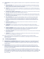
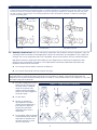
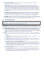
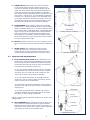
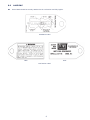
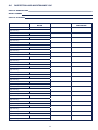
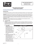
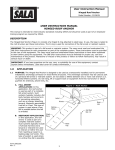
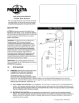
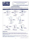
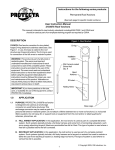
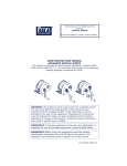
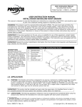
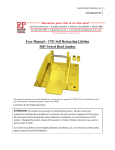
Instructions for the following series products:
Hinged Roof Anchor
Model Number: 2101719
User Instruction Manual
2103676 Roof Anchors
This manual is intended to meet industry standards including OSHA and should be used as part of an
employee training program as required by OSHA.
DESCRIPTION
Figure 1 - Roof Anchor
2103676: Roof anchor consists of a forged D-ring
attached to steel base. In use, the base is nailed to
the roof structure per these instructions. The D-ring
is used for connection of the fall arrest or restraint
system. See Figure 1.
WARNING: This product is part of a fall arrest
or restraint system. The users must read and
understand manufacturer’s instructions for each
component or part of the complete system. These
instructions must be provided to the user of this
equipment. The users must read and understand
these instructions or have them explained to
them before using this equipment. Manufacturer’s
instructions must be followed for proper use,
care and maintenance of this product. Alterations
or misuse of this product or failure to follow
instructions, may result in serious injury or death.
D-Ring
Label
Rivets
16d Nail
Qty 12
IMPORTANT: If you have questions on the use,
care, or suitability for use of this equipment,
contact DBI‑SALA immediately.
1.0
Steel
Base
APPLICATION
Nailing
Holes
1.1 PURPOSE: DBI‑SALA’s 2103676 roof anchor is
designed to be used as a temporarily installed
(not for permanent installation) anchorage
connector on wood frame structures. This
anchorage connector may be used as part of
a personal fall arrest or restraint system. Do
not attach a lifeline between two or more roof
anchors (i.e. horizontal lifeline system). Do
not hang, lift or support tools or equipment
from this roof anchor or attach guylines for
antennas, phone lines, etc.
Base
Legs
A. FALL ARREST APPLICATION: In this application, the roof anchor is used as part of a complete
fall arrest system. Such systems typically include a full body harness and some form of connecting
subsystem, such as an energy absorbing lanyard. Maximum permissible free fall is six feet. This type of
system is used where a free fall is possible before the fall is arrested.
B. RESTRAINT APPLICATION: In this application, the roof anchor is used as part of a complete restraint
system. Such systems typically include a full body harness and a lanyard or restraint line used to
restrain or tether the user from reaching a hazard (i.e. leading edge roof work). This type of system is
used where no vertical free fall is possible.
© Copyright 2006, DB Industries, Inc.
1.2 LIMITATIONS: The following application limitations must be recognized and considered before using this
product:
A. ROOF STRUCTURE: This anchorage connector is intended to be installed on wood framed structures
capable of meeting the anchorage strength requirements as set forth in section 2.4. Consult DBI‑SALA
before using these roof anchors on any other roof material.
B. CAPACITY: This anchorage connector is designed for use by persons with a combined weight (person,
clothing, tools, etc.) of no more than 310 lbs. Only one personal protective system may be connected to
the roof anchor at any time.
C. PERSONAL FALL ARREST SYSTEM (PFAS) : PFAS’s selected for use with this roof anchor must meet
the system performance and other criteria as stated in section 3.2.
D. FREE FALL: PFAS’s used with these roof anchors must be rigged in such a way as to limit the free fall
to a maximum of 6 feet (reference ANSI Z359.1). See associated connecting subsystem manufacturer’s
instructions for further information.
E. FALL CLEARANCE: Make certain that enough clearance exists in your fall path to prevent striking
an object. The amount of clearance needed is dependent upon the type of connecting subsystem
used (energy absorbing lanyard, self retracting lifeline, etc.), and the anchorage location. Refer to
manufacturer’s instructions of the connecting subsystem or component for more information on fall
clearance.
F. RESTRAINT SYSTEMS: Restraint systems selected for use with this roof anchor must meet the
requirements given in section 3.2.
G. CORROSION: Use near sea water or other corrosive environments may require more frequent
inspections or servicing (replacement) to assure corrosion damage is not affecting the performance of
the product.
H. CHEMICAL HAZARDS: Solutions containing acids, alkali, or other caustic chemicals, especially at
elevated temperatures, may cause damage to this equipment. Consult DBI‑SALA if doubt exists
concerning installing this equipment where chemical hazards are present.
I. ELECTRICAL HAZARDS: Do not install roof anchors where they or the user may come into contact with
electrical power lines.
J. TRAINING: This equipment is intended to be installed and used by persons who have been properly
trained on its correct application. See section 4.0.
1.3 Refer to national consensus (including ANSI Z359.1, applicable local, state, and federal (OSHA)
requirements) governing this equipment for more information on anchorage connectors, and associated
system components.
2.0
SYSTEM REQUIREMENTS
2.1 COMPATIBILITY OF CONNECTORS: DBI‑SALA equipment is designed for use with DBI‑SALA approved
components and subsystems only. Substitutions or replacements made with non-approved components
or subsystems may jeopardize compatibility of equipment and may effect the safety and reliability of the
complete system.
2.2 COMPATIBILITY: Connectors are considered to be compatible with connecting elements when they
have been designed to work together in such a way that their sizes and shapes do not cause their gate
mechanisms to inadvertently open regardless of how they become oriented. Contact DBI‑SALA if you have
any questions about compatibility.
Connectors (hooks, carabiners, and D-rings) must be capable of supporting at least 5,000 lbs. (22.2kN).
Connectors must be compatible with the anchorage or other system components. Do not use equipment that
is not compatible. Non-compatible connectors may unintentionally disengage. See Figure 2. Connectors must
be compatible in size, shape, and strength. Self locking snap hooks and carabiners are required by ANSI
Z359.1 and OSHA.
Figure 2 - Unintentional Disengagement (Roll-out)
If the connecting element that a snaphook (shown) or carabiner attaches to is undersized or irregular in shape, a situation
could occur where the connecting element applies a force to the gate of the snaphook or carabiner. This force may cause
the gate (of either a self-locking or a non-locking snaphook) to open, allowing the snaphook or carabiner to disengage
from the connecting point.
Small ring or other
non-compatibly
shaped element
1. Force is applied to the
snap hook.
2. The gate presses against the
connecting ring.
3. The gate opens allowing the
snap hook to slip off.
2.3 Making Connections: Only use self-locking snap hooks and carabiners with this equipment. Only use
connectors that are suitable to each application. Ensure all connections are compatible in size, shape and
strength. Do not use equipment that is not compatible. Ensure all connectors are fully closed and locked.
DBI‑SALA connectors (snap hooks and carabiners) are designed to be used only as specified in each
product’s user’s instructions. See Figure 3 for inappropriate connections. DBI‑SALA snap hooks and
carabiners should not be connected:
A. To a D-ring to which another connector is attached.
B. In a manner that would result in a load on the gate.
NOTE: Large throat opening snap hooks should not be connected to standard size D-rings or similar objects
which will result in a load on the gate if the hook or D-ring twists or rotates. Large throat snap hooks are
designed for use on fixed structural elements such as rebar or cross members that are not shaped in a way that
can capture the gate of the hook.
C. In a false engagement, where
features that protrude from
the snap hook or carabiner
catch on the anchor and
without visual confirmation
seems to be fully engaged to
the anchor point.
Figure 3 - lnappropriate Connections
D. To each other.
E. Directly to webbing or
rope lanyard or tie-back
(unless the manufacturer’s
instructions for both the
lanyard and connector
specifically allow such a
connection).
F. To any object which is shaped
or dimensioned such that the
snap hook or carabiner will
not close and lock, or that
roll-out could occur.
2.4 ANCHORAGE STRENGTH: Depending on the application, the anchorage to which the roof anchor is
installed must meet strengths as given below:
FALL ARREST: Roof anchors installed for fall arrest applications must be attached to a roof member
capable of sustaining static loads in the direction(s) permitted by the PFAS when in use of at least: (A)
3,600 lbs. (16kN) when certification exists (reference ANSI Z359.1 for certification definition); or (B) 5,000
lbs. (22.2kN) in absence of certification. See Figure 4 for roof anchor loading direction limitations. When
more than one roof anchor is installed to a roof structure, the strengths given in (A) or (B) above must be
met at each roof anchors installation point independently. EXAMPLE: If two roof anchors are installed onto a
roof structure, each anchor location must be independently capable of supporting 5,000 lbs. (or 3,600 lbs.
with certification).
From OSHA 1926.500 and 1910.66: Anchorages used for attachment of a personal fall arrest system
shall be independent of any anchorage being used to support or suspend platforms, and must support at
least 5,000 lbs. per user attached; or be designed, installed, and used as part of a complete personal fall
arrest system which maintains a safety factor of at least two, and is supervised by a qualified person.
RESTRAINT: Roof anchors installed for restraint applications must be attached to a roof member capable of
sustaining a static load of at least 3,000 lbs. applied in any direction permitted by the restraint system when
in use. Each roof anchor installation must be independently capable of sustaining this load.
3.0
OPERATION AND USE
WARNING: Do not alter or intentionally misuse this equipment. Consult with DBI‑SALA if using this equipment
with components or subsystems other than those described in this manual. Some subsystem and component
combinations may interfere with the operation of this equipment. Use caution when using this equipment around
moving machinery, electrical hazards, chemical hazards, and sharp edges.
WARNING: Do not use this system if you are unable to tolerate the impact of a fall arrest. Age and fitness can
seriously affect your ability to withstand a fall. Pregnant women and minors must not use this equipment.
3.1 BEFORE INSTALLATION of this equipment, carefully inspect it to assure it is in serviceable condition.
Check for missing or damaged parts, see Figure 1. Legs of the metal base should be flat and free of tears or
corrosion. Rivets should be tight and securely clinched. Check for installation nails (twelve 16d nails). Refer
to section 5.0 for further inspection details. Do not use if inspection reveals an unsafe condition. NOTE: The
2103676 is designed as a multi-use anchor. Teks screws may not be reused.
3.2 PLAN your fall arrest or restraint system before starting your work. Take into consider all factors affecting
your safety at any time during use. The following list gives some important points to consider when planning
your system:
A. ANCHORAGE: Select an anchorage point that is rigid and capable of supporting the required loads. See
section 2.4. Locate the roof anchor in accordance with section 3.3.
B. FREE FALL: PFAS’s must be rigged to limit any free fall to a maximum of 6 feet (OSHA and ANSI
Z359.1), restraint systems must be rigged such that no vertical free fall is possible. Avoid working above
your anchorage level since an increased free fall distance will result.
C. PERSONAL FALL ARREST SYSTEM REQUIREMENT: PFAS’s used with this roof anchor must meet
applicable OSHA, state, federal, and ANSI requirements. PFAS’s incorporating a full body harness must
be capable of arresting a workers fall with maximum arresting force of no greater than 1,800 lbs. and
limit the free fall distance to 6 feet or less. The deceleration distance for PFAS must be 42 inches (1.1m)
or less. Reference ANSI Z359.1 and OSHA requirements.
D. RESTRAINT SYSTEMS: Restraint systems must meet applicable state and federal requirements.
E. FALL CLEARANCE: Should a fall occur, there must be sufficient clearance in the fall area to arrest the
fall before striking the ground or other objects. The actual clearance required is dependent upon the
type of fall arrester connecting subsystem used (energy absorbing lanyard, self retracting lifeline, etc.).
Refer to manufacturer’s instructions for fall clearance information.
F. SWING FALLS: Swing falls occur when the anchor
is not directly above the point where a fall occurs.
The force of striking an object while swinging can be
great and cause serious injury. Minimize swing falls by
working as directly below the anchorage as possible
(the worker must be positioned within 30 degrees of the
roof anchor), see Figure 4. It is acceptable to captivate
a lifeline (i.e. rope grab system) to an anchorage close
to the work area with a carabiner, see Figure 4. Do not
captivate the lifeline of a self retracting lifeline as this
may affect the performance of its internal braking.
G. SHARP EDGES: Avoid working where the connecting
subsystem (i.e. shock absorbing lanyard, self retracting
lifeline, full body harness, etc.) or other components will
be in contact with, or abrade against, unprotected sharp
edges. Do not the loop lanyard around small diameter
structural members. If working with equipment near
sharp edges is unavoidable, protection against cutting
must be provided by using a heavy pad or other means
over the exposed sharp edge.
Figure 4 - Swing Fall
Roof Anchor
ROOF PEAK
R
O
O
F
E
D
G
E
Working Range
ROOF EDGE
Loading Direction Limitations
H. RESCUE: Should a fall occur, the user (employer) must
have a rescue plan and the means at hand to implement
it.
I. AFTER A FALL: Any equipment which has been
subjected to the force of arresting a fall must be
removed from service immediately and destroyed, or
contact a factory authorized service center for repair.
Gable End Swing Fall
3.3 INSTALLATION REQUIREMENTS.
A. ROOF ANCHOR SITE PLAN: Before starting the roof
construction, a plan should be established as to where
the roof anchors will be installed, and when during the
construction process they may be used. The following
are guidelines on locating roof anchors:
• The roof anchor should be located at the roof peak
(when possible) and at least 6 feet from any exposed
roof edge. On very small roof areas, locate the roof
anchor as far from the roof edge as possible.
• Do not install roof anchors on unsupported roof
structures, such as eaves or gable overhangs. Do not
install roof anchors on facia boards.
• Roof anchors should be installed at 8 foot spacings
along the roof ridge. Hip roofs require a roof anchor on
each hip face.
• On long low pitched roofs, multiple roof anchors
should be installed along the gable ends (6 feet from
the edge) to reduce swing fall hazards.
Figure 5 shows typical roof anchor locations for various roof
configurations.
B. ROOF FRAMING: Roof framing members to which the
roof anchors are attached must be in good condition.
Members must be free of splits, cracks, large knots, or
defects that may weaken the member. Do not attach the
roof anchor to rotted or deteriorated wood.
Swing Fall Hazard
ROOF PEAK
R
O
O
F
E
D
G
E
Lifeline
Roof Anchor
Carabiner
Rope Grab
ROOF EDGE
Captivating A Lifeline
Figure 5 - Anchor Installation
At Least One Anchor On Hip Roof
C.fasteners: The roof anchor may be secured to the roof using either 16d nails (as supplied) or Teks
screws (1/4-14 screws need to be long enough for five threads to be exposed beyond the purlins).
D. ROOF ANCHOR INSTALLATION: Roof
anchors must be installed in accordance with
the previously discussed site plan. Site work
rules must be followed regarding when an
installed roof anchor is ready for use (i.e. after
sheathing is in place).
Figure 6 - Anchor Installation
ATTACHING THE ROOF ANCHOR: Spread
the anchor base legs apart to match the
surface it will be mounted on, either a roof
peak or a flat surface. Position the anchor on
the roof such that the 12 nail holes along the
center of the legs are over (framing) member.
Then, push down to minimize any gap
between the anchor and the sheathing and
nail. Use only 16d nails to install the anchor
(six per leg into the rafters and sheathing).
Install all 12 nails. See Figures 6 and 7. See
section 5.0 for pre-use inspection.
WARNING: The 2103676 roof anchor must be positioned on top of previously secured roof sheathing (do
not attach directly to rafter or truss member). All 12 nails must be installed. If the roof anchor is not installed
properly, it will not hold the rated loads and serious injury or death could occur.
WARNING: Use only 16d nails which have a complete
head. Do not use nails from nail guns. Never attach the
roof anchor with the legs still together (legs must be
spread apart).
Figure 7 - Anchor Installation
Roof Anchor
Sheathing
Rafter or
E. STEEL DECKING INSTALLATION: This
16d Nails
Truss
anchor may be installed on steel decking with
a minimum material thickness of 22 gauge
(.030 inch) over Z-purlins with a minimum
material thickness of 16 gauge (.064 inch).
The maximum span between purlins is 6 feet.
Twelve 1/4-14 Teks screws are required to
fasten the anchor. The screws should be of
sufficient length so that at least five threads
are exposed beyond the bottom of the purlin.
The screws must be located on the outer
two of the long rows of holes, through every
other hole. Every screw must penetrate the Z‑purlin. The holes in the anchor that will be used with the
Teks screws must to be drilled out to 1/4 inch diameter, see Figure 8. The anchor should not be used
as a permanent anchor once the holes have been drilled out because the corrosion protectin has been
damaged. The anchoring structure needs to meet the requirements of Section 2.4.
Figure 8 - Teks Screw Hole Pattern
Warning: Anchors that have been drilled out
may not be reused. After use, the anchor must be
removed from service and destroyed.
F. REMOVAL OF ROOF ANCHOR: Remove
the roof anchor prior to shingling the area
with the anchor. To remove it, pry off the
anchor from the roof. If Teks screws are used
to attach the anchor, the screws should be
removed rather than just prying the anchor
from the roof.
When using Teks screws, only drill out the darkened holes
to 1/4 in. diameter.
NOTE: The 2103676 is designed as a multi-use anchor. New 16d nails must be used for every reinstallation.
3.4 CONNECTING TO THE ROOF ANCHOR: Connection to the installed roof anchor may be made using a
self locking snap hook or self locking and self closing carabiner only. Do not use a knot to connect a lifeline
to the roof anchor. Do not pass the lanyard or lifeline through the roof anchor D-ring and hook back into
the lanyard or lifeline. When connecting, make sure the connections are fully closed and locked. Figure 9
illustrates the proper connection of a typical fall arrest or restraint equipment to the roof anchor. When using
an energy absorbing lanyard, connect the energy absorber “pack” end to the harness. When using a self
retracting lifeline, make sure the device is properly positioned so that the retraction is not hindered. Always
protect the lifeline/lanyard from abrading against sharp or abrasive surfaces on the roof. Make sure all the
connections are compatible in size, shape, and strength. Never connect more than one personal protective
system to any single roof anchor at a time.
WARNING: Read and follow manufacturer’s instructions for associated equipment (i.e. full body harness, shock
absorbing lanyard, self retracting lifeline, etc.) used in your personal fall arrest system.
WARNING: For special (Custom) versions of this product, follow the instructions herein. If enclosed, see
attached supplement for additional instructions to be followed when using a customized product.
Figure 9 - Making Connections
Self Retracting Lifeline
Full Body
Harness
Rope Grab
Lifeline
Roof Anchor
Roof Anchor
Lanyard
Energy Absorber
4.0
TRAINING
4.1 It is the responsibility of all users of this equipment to understand these instructions, and to be trained in
the correct installation, use, and maintenance of this equipment. These individuals must be aware of the
consequences of improper installation or use of this equipment. This user manual is not a substitute for a
comprehensive training program. Training must be provided on a periodic basis to ensure proficiency of the
users.
IMPORTANT: Training must be conducted without exposing the trainee to a fall hazard. Training should be
repeated on a periodic basis.
5.0
INSPECTION
5.1 FREQUENCY:
A. Before each use, visually inspect the equipment per steps listed in sections 5.2 and 5.3.
B. The roof anchor must be inspected by a competent person other than the user at least annually. See
sections 5.2 and 5.3 for guidelines. Record the results of each formal inspection in the inspection log
found in section 9.0. NOTE: Cal/OSHA requires personal fall arrest systems be inspected prior to each
use for wear, damage, and defects and inspected by a competent person* at least twice a year, in
accordance with the manufacturer’s recommendations, with inspection dates documented.
IMPORTANT: If this equipment has been subjected to forces resulting from the arrest of a fall, it must be
immediately removed from service and destroyed or returned to DBI‑SALA for possible repair. See section 5.2.
*Competent person: An individual knowledgeable of a manufacturer’s recommendations, instructions and
manufactured components who is capable of identifying existing and predictable hazards in the proper selection,
use and maintenance of fall protection.
5.2 INSPECTION STEPS:
Step 1. Inspect the Roof Anchor for physical damage. Look carefully for any signs of cracks, dents, or
deformities in the metal. Check for bending, the roof anchor legs should be flat. Rivets should be
securely attached and fully clinched (not pulling through hole).
Step 2. Inspect the Roof Anchor for signs of excessive corrosion.
Step 3. Ensure the condition of the roof anchor will support the Roof Anchor loads, see section 2.4. An
anchor connected to rotten or deteriorated wood should not be used.
Step 4: Ensure the Roof Anchor is still securely attached. If loose, do not use.
Step 5: Inspect each system component or subsystem per associated manufacturer’s instructions.
Step 6: Record the inspection date and results on the inspection log. See section 9.0.
5.3 If inspection reveals a defective condition, remove unit from service immediately and destroy, or contact a
factory authorized service center for repair.
NOTE: Only DBI‑SALA or parties authorized in writing may make repairs to this equipment.
6.0
MAINTENANCE, SERVICE, AND STORAGE
6.1 No scheduled maintenance is required. If you have any questions concerning the condition of your Roof
Anchor, or have any doubt about putting it into service, contact DBI‑SALA immediately.
6.2 Additional maintenance and servicing procedures (i.e. replacement parts) must be completed by a factory
authorized service center. Authorization must be in writing.
7.0
SPECIFICATIONS
Material: Forged alloy D-ring and 1/8 in. thick steel
Minimum Breaking Strength: 3,600 lbs. when loaded within the loading
direction limitations as shown in Figure 4.
Weight: 1.8 lbs.
Size: 5/8 in. x 4 in. x 17 in.
Capacity: 310 lbs. (one person)
8.0LABELING
8.1 These labels should be securely attached to the roof anchor and fully legible.
Installation Label
Back
Front
Roof Anchor Label
9.0inspection and maintenance log
Date of manufacture
model number
date of purchase
Inspection date
inspection items
noted
corrective action
Approved by:
Approved by:
Approved by:
Approved by:
Approved by:
Approved by:
Approved by:
Approved by:
Approved by:
Approved by:
Approved by:
Approved by:
Approved by:
Approved by:
Approved by:
Approved by:
Approved by:
Approved by:
Approved by:
10
maintenance
performed
9.0inspection and maintenance log
Date of manufacture
model number
date of purchase
Inspection date
inspection items
noted
corrective action
Approved by:
Approved by:
Approved by:
Approved by:
Approved by:
Approved by:
Approved by:
Approved by:
Approved by:
Approved by:
Approved by:
Approved by:
Approved by:
Approved by:
Approved by:
Approved by:
Approved by:
Approved by:
Approved by:
11
maintenance
performed
A Capital Safety Brand
USA
3833 SALA Way
Red Wing, MN 55066-5005
Toll Free: 800-328-6146
Phone: (651) 388-8282
Fax: (651) 388-5065
www.capitalsafety.com
Canada
260 Export Boulevard
Mississauga, Ontario L5S 1Y9
Toll Free: 800-387-7484
Phone: (905) 795-9333
Fax: (905) 795-8777
www.capitalsafety.com
This instruction manual is available for download at www.capitalsafety.com.
I S O
9001
Certificate No. FM 39709
12
Form: 5902201
Rev: B