1
pure::variants Eclipse Plug-in
User's Guide
Version 2.0 for pure::variants 2.2
pure::variants Eclipse Plug-in User's Guide: Version 2.0
for pure::variants 2.2
Published 2006
Copyright © 2003-2006 pure-systems GmbH
Table of Contents
1. Introduction .................................................................................................... 1
1.1. What is pure::variants? ......................................................................... 1
1.2. Other related documents ....................................................................... 2
2. Getting Started ................................................................................................ 3
2.1. Software Requirements ......................................................................... 3
2.2. Software Installation ............................................................................. 3
2.2.1. How to install the software ......................................................... 3
2.2.2. Installation Problems ................................................................. 3
2.3. Obtaining and Installing a License ......................................................... 3
2.4. The Variant Management Perspective .................................................... 4
2.5. Using Feature Models ........................................................................... 4
2.6. Using Configuration Spaces .................................................................. 5
2.7. Viewing and Exporting Configuration Results ........................................ 7
2.8. Transforming Configuration Results ...................................................... 7
2.9. Exploring Documentation and Examples ............................................... 9
3. Concepts ...................................................................................................... 11
3.1. Introduction ....................................................................................... 11
3.2. Common Concepts in pure::variants models ......................................... 12
3.2.1. Model Constraints ................................................................... 12
3.2.2. Element Restrictions ................................................................ 13
3.2.3. Element Relations ................................................................... 13
3.2.4. Element Attributes ................................................................... 13
3.3. Feature Models .................................................................................. 16
3.3.1. Feature Attributes .................................................................... 17
3.4. Family Models ................................................................................... 17
3.4.1. Structure of the family model ................................................... 17
3.4.2. Sample family model ............................................................... 18
3.4.3. Restrictions in Family Models .................................................. 20
3.4.4. Relations in Family Models ...................................................... 20
3.5. Model Evaluation ............................................................................... 21
3.5.1. Evaluation Algorithm .............................................................. 22
3.5.2. Automatic Selection Problem Resolving ................................... 23
3.6. Model Transformation ........................................................................ 24
3.6.1. The Transformation Process ..................................................... 24
3.6.2. pure::variants Transformation Input .......................................... 25
3.7. Model Validation ............................................................................... 26
3.7.1. XML Schema Model Validation ............................................... 27
3.7.2. Model Check Framework ......................................................... 27
4. Tasks ........................................................................................................... 31
4.1. Generating Variants with Model Transformations ................................ 31
4.1.1. Using the Standard Transformation ........................................... 31
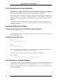
4.1.2. Using XSLT for the Transformation ......................................... 33
5. Graphical User Interface ................................................................................ 37
5.1. Getting Started with Eclipse ................................................................ 37
5.2. Variant Management Perspective ........................................................ 38
5.3. Editors ............................................................................................... 39
5.3.1. Common Editor Actions .......................................................... 40
5.3.2. Common Editor Pages ............................................................. 41
5.3.3. Feature Model Editor ............................................................... 55
5.3.4. Family Model Editor ............................................................... 57
5.3.5. Variant Description Model Editor ............................................. 58
5.3.6. Configuration Space Editor ...................................................... 60
v
pure::variants Eclipse Plug-in User's
Guide
5.3.7. Model Compare Editor ............................................................ 64
5.4. Views ................................................................................................ 67
5.4.1. Attributes View ....................................................................... 67
5.4.2. Filter View .............................................................................. 67
5.4.3. Search View ............................................................................ 67
5.4.4. Outline View ........................................................................... 69
5.4.5. Problem View/Task View ........................................................ 69
5.4.6. Properties View ....................................................................... 69
5.4.7. Relations View ........................................................................ 69
5.4.8. Result View ............................................................................ 70
5.4.9. Feature Matrix View ................................................................ 72
5.4.10. Variant Projects View ............................................................ 73
5.5. Search ............................................................................................... 74
5.5.1. Search String ........................................................................... 75
5.5.2. Search Type ............................................................................ 76
5.5.3. Limit To ................................................................................. 76
5.5.4. Element Scope ........................................................................ 76
5.5.5. Attribute Scope ....................................................................... 76
5.5.6. Scope ..................................................................................... 77
5.5.7. Search Results ......................................................................... 77
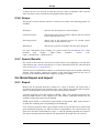
5.6. Model Export and Import .................................................................... 77
5.6.1. Export .................................................................................... 77
5.6.2. Import .................................................................................... 79
6. Additional pure::variants Plug-ins .................................................................. 81
7. Reference ..................................................................................................... 83
7.1. Abbreviations .................................................................................... 83
7.2. Keyboard Shortcuts ............................................................................ 83
7.3. Element Attributes ............................................................................. 84
7.4. Element Relations .............................................................................. 85
7.5. Expression Language pvProlog ........................................................... 87
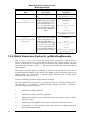
7.5.1. Additional Restriction Rules for Variant Evaluation ................... 96
7.5.2. Match Expression Syntax for getMatchingElements .................. 96
7.5.3. Model Attributes ..................................................................... 97
7.6. Expression Language pvSCL .............................................................. 97
7.7. Feature Models ................................................................................ 100
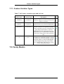
7.7.1. Feature Variation Types ......................................................... 101
7.8. Family Models ................................................................................. 101
7.8.1. Predefined Source Element Types .......................................... 102
7.8.2. Predefined Part Element Types ............................................... 109
7.9. Variant Description Models .............................................................. 111
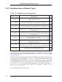
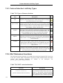
7.9.1. Feature Selection List Entry Types ......................................... 112
7.10. XSLT Extension Functions ............................................................. 112
8. Appendices ................................................................................................. 117
8.1. Software Configuration .................................................................... 117
8.2. User Interface Advanced Concepts .................................................... 117
8.2.1. Console View ........................................................................ 117
8.3. Glossary .......................................................................................... 118
Index ............................................................................................................. 121
vi
List of Figures
1.1. pure::variants transformation process ............................................................. 1
2.1. Initial layout of the “Variant Management” perspective .................................. 4
2.2. A simple feature model of a car ..................................................................... 5
2.3. Variant model with a problematic selection .................................................... 6
2.4. Variant model export wizard (HTML export of all models selected) ................ 7
2.5. Transformation configuration in configuration space properties ....................... 8
2.6. Transformation button in Eclipse toolbar ....................................................... 9
3.1. Overview of family-based software development with pure::variants ............. 11
3.2. (simplified) element meta model ................................................................. 12
3.3. (Simplified) element attribute meta-model ................................................... 14
3.4. Basic structure of feature models ................................................................. 16
3.5. Basic structure of family models ................................................................. 17
3.6. Sample family model .................................................................................. 19
3.7. Model Evaluation Algorithm (Pseudo Code) ................................................ 22
3.8. Automatically Resolved Feature Selections .................................................. 24
3.9. XML Transformer ...................................................................................... 25
3.10. Model Validation Preferences Page ........................................................... 28
3.11. New Check Configuration Dialog .............................................................. 29
3.12. Model Validation in Progress .................................................................... 30
4.1. The Standard Transformation Type Model ................................................... 31
4.2. Multiple attribute definitions for Value calculation ....................................... 32
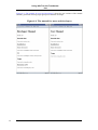
4.3. Variant project describing the manual .......................................................... 34
4.4. The manual for users and developers ........................................................... 36
5.1. Eclipse workbench elements ....................................................................... 38
5.2. Variant management perspective standard layout ......................................... 39
5.3. Filter definition dialog ................................................................................ 40
5.4. Metrics for a model .................................................................................... 41
5.5. Constraints view ........................................................................................ 43
5.6. Selected Element Selection Tool ................................................................. 46
5.7. Feature/Family Model Element Creation Tools ............................................ 46
5.8. Sample attribute definitions for a feature ...................................................... 48
5.9. Restrictions page shown in property editor ................................................... 49
5.10. Constraints page shown in property editor .................................................. 50
5.11. Advanced pvSCL expression editor ........................................................... 51
5.12. Advanced pvProlog expression editor ........................................................ 52
5.13. pvProlog expression pilot .......................................................................... 53
5.14. Element selection dialog ........................................................................... 54
5.15. Feature model editor with outline and property view ................................... 55
5.16. Feature property dialog ............................................................................. 56
5.17. Open family model editor with outline and property view ........................... 58
5.18. Variant description model editor with outline, result, problems, and attributes
view ................................................................................................................ 59
5.19. Outline view showing the list of available features in a variant description model ..................................................................................................................... 60
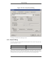
5.20. Configuration space properties: Model Selection ........................................ 61
5.21. Configuration space properties: Transformation input/output paths .............. 62
5.22. Configuration space properties: Transformation Configuration .................... 63
5.23. Model Compare Editor ............................................................................. 66
5.24. Attributes view (right) showing the attribute Count for feature Gears ........... 67
5.25. Variant Search View (Tree) ....................................................................... 68
5.26. Variant Search View (Table) ..................................................................... 68
5.27. Relations view (different layouts) for feature with a “ps:requires” to feature
'Main Component Big' ...................................................................................... 70
vii
pure::variants Eclipse Plug-in User's
Guide
5.28. Result View ............................................................................................. 71
5.29. Result View in Delta Mode ....................................................................... 72
5.30. Feature Matrix view of a configuration space ............................................. 73
5.31. The “Variant Projects” view ...................................................................... 74
5.32. The Variant Search Dialog ........................................................................ 75
5.33. Directed Graph Export Output Configuration Dialog .................................. 78
5.34. Directed graph export example (options LR direction, Colored) .................. 79
8.1. The configuration dialog of pure::variants .................................................. 117
viii
List of Tables
3.1. Mapping between input and result model types ............................................ 25
5.1. Variables available for path resolution in transformations ............................. 61
7.1. Common Keyboard Shortcuts ..................................................................... 83
7.2. Model Editor Keyboard Shortcuts ............................................................... 84
7.3. Graph Editor Keyboard Shortcuts ................................................................ 84
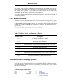
7.4. Supported Attribute Types .......................................................................... 84
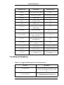
7.5. Supported Relations between Elements (I) ................................................... 85
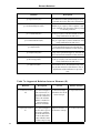
7.6. Supported Relations between Elements (II) .................................................. 86
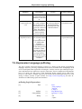
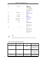
7.7. Logic operators in pvProlog ........................................................................ 88
7.8. Functions in pvProlog ................................................................................. 88
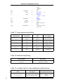
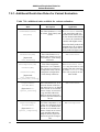
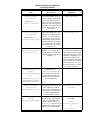
7.9. Available rules for Value calculations and Restrictions ................................. 88
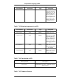
7.10. Additional rules available for variant evaluation ......................................... 94
7.11. Meta-Model attributes in pvProlog ............................................................ 97
7.12. Logic operators in pvSCL ......................................................................... 98
7.13. Relational operators in pvSCL ................................................................... 99
7.14. Functions in pvSCL .................................................................................. 99
7.15. Element references ................................................................................... 99
7.16. Feature variation types and its icons ........................................................ 101
7.17. Predefined source element types .............................................................. 102
7.18. Predefined part types .............................................................................. 109
7.19. Types of feature selections ...................................................................... 112
7.20. XSLT extension functions ....................................................................... 112
ix
x
List of Examples
7.1. A sample conditional document for use with the ps:condxml transformation 105
7.2. A sample conditional document for use with the ps:condtext transformation 106
7.3. Generated code for a ps:flagfile for flag "DEFAULT" with value "1" .......... 107
7.4. Generated code for a ps:makefile for variable "CXX_OPTFLAGS" with value "O6" ................................................................................................................ 107
7.5. Generated code for a ps:classalias for alias "io::net::PCConn" with aliased class
"NoConn" ...................................................................................................... 108
xi
xii
Chapter 1. Introduction
1.1. What is pure::variants?
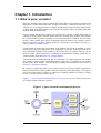
The pure::variants Eclipse plug-in extends the Eclipse IDE to support the development and
deployment of software product lines. Using pure::variants, a software product line is developed as a set of integrated Feature models describing the problem domain, Family models describing the problem solution and Variant Description models specifying individual
products from the product line.
Feature models describe the products of a product line in terms of the features that are
common to those products and the features that vary between those products. Each feature
in a Feature model represents a property of a product that will be visible to the user of that
product. These models also specify relationships between features, for example, choices
between alternative features. Feature models are described in more detail in Figure 3.4,
“Basic structure of feature models”.
Family models describe how the products in the product line will be assembled or generated from pre-specified components. Each component in a Family model represents one or
more functional elements of the products in the product line, for example software (in the
form of classes, objects, functions or variables) or documentation. Family models are described in more detail in Section 3.4, “Family Models”.
Variant Description models describe the set of features of a single product in the product
line. Taking a Feature model and making choices where there is variability in the Feature
model creates these models. Variant Description models are described in more detail in
Section 3.5, “Model Evaluation”.
In contrast to other approaches, pure::variants captures the Feature model (problem domain) and the Family model (problem solution) separately and independently. This separation of concerns makes it simpler to address the common problem of reusing a Feature
model or a Family model in other projects.
Figure 1.1, “pure::variants transformation process” gives an overview of the basic process
of creating variants with pure::variants.
Figure 1.1. pure::variants transformation process
1
Other related documents
The product line is built by creating Feature and Family models. Once these models have
been created, individual products may be built by creating Variant Description models. Responsibility for creation of product line models and creation of product models is usually
divided between different groups of users.
1.2. Other related documents
The “Workbench User Guide” (“Help”->”Help Contents”) is a good starting point for familiarising yourself with the Eclipse user interface.
The pure::variants XML transformation system is described in detail in the XML Transformation System Manual (see Eclipse online help for a HTML version).
Features specific to the pure::variants Server Edition are described in a separate section in
this document in the PVEP Plugins chapter (if reading the Eclipse help variant of the
manual with an installed Server Edition feature) or in a separate PDF file.
The pure::variants Extensibility Guide is a reference document for information about extending and customizing pure::variants, e.g. with customer-specific user interface elements
or by integrating pure::variants with other tools.
This document is available in online help as well as in printable PDF format here.
2
Chapter 2. Getting Started
2.1. Software Requirements
The following software has to be present on the user's machine in order to support the
pure::variants Eclipse plug-in:
Operating System:
Windows 2000, Windows XP, Linux or MacOS X 10.3
Eclipse:
Eclipse 3.0 or higher required. Eclipse is available from http://www.eclipse.org/.
Java:
Eclipse requires a Java Virtual Machine (JVM) to be installed.
We recommend using a Sun JDK 1.4 or 1.5 compatible JVM.
See http://www.java.com/ for a suitable JVM.
2.2. Software Installation
2.2.1. How to install the software
pure::variants software is distributed and installed in one of three ways:
• Installing from an Update Site Installation via the Eclipse update mechanism is a convenient way of installing and updating pure::variants from an internet site. The location
of the site depends on the pure::variants edition. Visit the pure-systems web site (http://web.pure-systems.com) or read your registration e-mail to find out which site is relevant for the version of the software your are using. Open the page in your browser to
get additional information how to use update sites with Eclipse 3.0.
• Archived Update Site pure::variants uses now the format of archived update sites, distributed as ZIP files, for offline installation. pure::variants archived update site file
names start with “updatesite” followed by an identification of the contents of the update
site. Installation is almost identical to normal update site installation. Simply follow the
instructions for normal update sites (above). But instead of using the “New Remote Site”
button, use the “Archived Site” button to navigate to and select the ZIP file.
• ZIP file Some pure::variants extensions may be distributed in simple ZIP files instead of
as archived update site. To install such extensions unpack the contents of this file into
the directory where Eclipse is installed. Additional Eclipse features and Eclipse plugins
may also be installed during this process.
2.2.2. Installation Problems
If you experience problems when installing new or updated plug-ins it can help to remove
any previous installation of the plug-in by removing all directories starting with
com.ps.consul from the features and plug-ins subdirectories of your Eclipse installation.
2.3. Obtaining and Installing a License
A valid license is required in order to use pure::variants. If pure::variants is started and no
license is present, then the user is prompted to supply a license. By selecting the Request
3
The Variant Management Perspective
License button a software registration form is opened in the user's default web browser.
After submitting the form, a license file is generated and sent to the e-mail address specified by the user. Select the Yes button and use the file dialog to specify the license file to
install. The specified license will be stored in the current workspace. If the user has different workspaces, then the license file has to be installed in each of them.
2.4. The Variant Management Perspective
The easiest way to access the variant management functionality is to use the Variant Management perspective provided by the plug-in. Use Window->Open Perspective->Other and
choose Variant Management to open this perspective in its default layout. The Variant
Management perspective should now open as shown below.
Figure 2.1. Initial layout of the “Variant Management” perspective
Now select the Variant Projects view in the upper left side of the Eclipse window. Create
an initial standard project using the context menu of this view and choose New->Variant
Project or use the File->New->Project wizard from the main menu. The view will now
show a new project with the given name.
Once the standard project has been created, three editor windows will be opened automatically: one for the Feature model, one for the Family model and one for the Variant Description model.
2.5. Using Feature Models
When a new Variant project is created a new feature model is also created with a root feature of the same name as the project's name. This name can be changed using the Proper4
Using Configuration Spaces
ties dialog of the feature. To create child features, use the New entry of the context menu
of the intended parent feature. A New Feature wizard allows a unique name, a visible
name, and the type of the feature and other properties to be specified. All properties of a
feature can be changed later using the Properties dialog.
The figure below shows a small example feature model for a car.
Figure 2.2. A simple feature model of a car
The Outline view (lower left corner) shows configurable views of the selected feature model and allows fast navigation to features by double-clicking the displayed entry.
The Properties view in the lower middle of the Eclipse window shows properties of the
currently selected feature.
The Details tab of the feature model editor (shown in the upper right part) provides a different view on the current feature. This view uses a layout and fields inspired by the Volere
requirements specification template to record more detailed aspects of a feature.
The Graph tab provides a graphical representation of the feature model. It also supports
most of the actions available in the feature model Tree view.
The Constraints tab contains a table with all constraints defined in the model supporting
full editing capabilities for the constraints.
2.6. Using Configuration Spaces
In order to create Variant Description models it is first necessary to create configuration
spaces. These are used to combine models for configuration purposes. The New5
Viewing and Exporting Configuration Results
>Configuration Space menu item starts the New Configuration Space wizard. Only the
names of the configuration space and at least one feature model have to be specified. The
initially created standard project configuration space is already configured in this way.
A variant description model has to be created inside the configuration space for each configuration. This is done using the context menu of the configuration space.
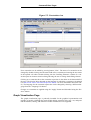
The variant description model editor is used to select the desired features for the variant.
This editor is also used to perform configuration validation. The Check Model button on
the toolbar, and the Variant->Check menu item, are used to perform an immediate validation of the feature selection. The Variant->Auto Check menu item enables or disables automatic validation after each selection change. The Variant->Auto Resolve menu item enables or disables automatic analysis and resolution of selection problems.
The problem view1 (lower right part) shows problems with the current configuration.
Double clicking on a problem will open the related element(s) in the Variant Description
Model editor. When used for the first time, Variant Management problems may be filtered
out. To resolve this, simply click on the filter icon
and select “Variant Management
Problems” as problem item to show. For some problems the “Quick fix” item in the context menu of the problem may offer options for solving the problem.
The figure below shows an example of a problem selection.
Figure 2.3. Variant model with a problematic selection
The Outline view shows a configurable list of features from all feature models in the configuration space.
1
Eclipse 3.0: The task view has been divided into tasks and problems view. Please open the problem view to see
evaluation problems.
6
Transforming Configuration Results
2.7. Viewing and Exporting Configuration Results
Results of a configuration can be accessed in a number of ways. The Result view
(Window->Show View->Other->Variant Management->Result) allows graphical review of
the variant result models that have been derived from the corresponding models in the configuration space.
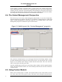
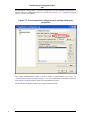
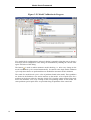
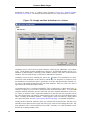
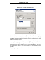
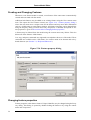
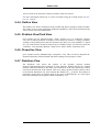
The context menu of the Variant Project view provides an Export operation. As shown in
the figure below, configuration results (features and components) can be exported as
HTML, XML, and CSV formats. The XML data format is the same as for importing models but contains only the configured elements. The Export dialog asks the user for a path
and name and the export data formats for the generated files, and the model types to export.
Figure 2.4. Variant model export wizard (HTML export of all models
selected)
2.8. Transforming Configuration Results
The last step in the automatic production of configured product variants is the transformation of the configuration results into the desired artefacts.
A modular, XML-based transformation engine is used to control this process (see Section 3.6, “Model Transformation”). The transformation process has access to all models
and additional parameters such as the input and output paths that have been specified in the
configuration space properties dialog. The transformation file could be a single XSLT file,
which is in turn executed with the configuration result as input, or a complete transformation module configuration.
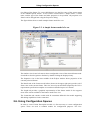
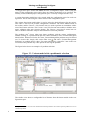
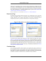
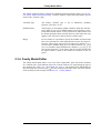
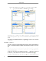
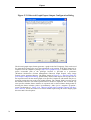
The transformation configuration for a configuration space is specified in its properties dialog. The Transformation Configuration page (Figure 2.5, “Transformation configuration in
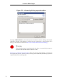
configuration space properties”) of this dialog allows the creation and modification of
7
Transforming Configuration Results
transformation configurations. A default configuration for the standard transformation is
created when the configuration space is created. See Section 5.3.6, “Configuration Space
Editor” for more information.
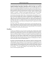
Figure 2.5. Transformation configuration in configuration space
properties
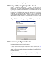
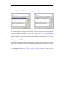
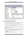
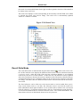
The toolbar transformation button is used to initiate a transformation (see Figure 2.6,
“Transformation button in Eclipse toolbar” ). For more information on the XML transformation engine, see the document “XMLTS Transformation Engine”.
The distributed examples include some sample transformations.
8
Exploring Documentation and Examples
Figure 2.6. Transformation button in Eclipse toolbar
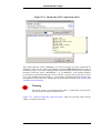
2.9. Exploring Documentation and Examples
Installing the "pure::variants User Documentation and Examples" feature gives access to
online help and examples of pure::variants usage. Online documentation is accessed using
"Help"->"Help Contents".
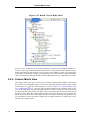
Examples can be installed as projects in the user's workspace by using
"File"->"New"->"Example". The available example projects are listed in the dialog below
the items "Variant Management" and "Variant Management SDK". Each example project
typically comes with a Readme.txt file that explains the concept and use of the example.
9
10
Chapter 3. Concepts
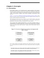
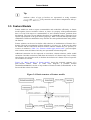
3.1. Introduction
pure::variants provides a set of integrated tools to support each phase of the software
product-line development process. pure::variants has also been designed as an open framework that integrates with other tools and types of data such as requirements management
systems, object-oriented modeling tools, configuration management systems, bug tracking
systems, code generators, compilers, UML or SDL descriptions, documentation, source
code, etc.
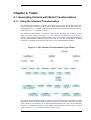
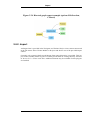
Figure 3.1, “Overview of family-based software development with pure::variants” shows
the four cornerstone activities of family-based software development and the models used
in pure::variants as the basis for these activities.
When building the infrastructure for your Product Line, the problem domain is represented
using hierarchical Feature Models. The solution domain, i.e. the concrete design and implementation of the software family, are implemented as Family Models.
The two models used for Application Engineering, i.e. the creation of product variants, are
complementary to the models described above. The Variant Description Model, containing
the selected feature set and associated values, represents a single problem from the problem
domain. The Variant Result Model describes a single concrete solution drawn from the
solution family.
Figure 3.1. Overview of family-based software development with
pure::variants
pure::variants manages the knowledge captured in these models and provides tool support
for co-operation between the different roles within a family-based software development
process:
• The domain analyst uses a feature model editor to build and maintain the problem domain model containing the commonalities and variabilities in the given domain.
• The domain designer uses a family model editor to describe the variable family architecture and to connect it via appropriate rules to the feature models.
11
Common Concepts in
pure::variants models
• The application analyst uses a variant description model to explore the problem domain
and to express the problems to be solved in terms of selected features and additional
configuration information. This information is used to derive a variant result model from
the family model(s).
• The application developer generates a member of the solution family from the variant
result model by using the transformation engine.
3.2. Common Concepts in pure::variants models
This section describes the common, generic structure on which both feature and family
models are based.
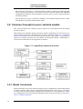
Both models store elements (features in feature models, components, parts and source elements in family models) in a hierarchical tree structure. Elements (Figure 3.2, “(simplified)
element meta model”) have an associated type and may have any number of associated attributes. An element may also have any number of associated relations. Additionally restrictions and constraints can be assigned to an element.
Figure 3.2. (simplified) element meta model
3.2.1. Model Constraints
Model constraints are used to check the integrity of the configuration (result model) during
a model evaluation. They can be assigned to model elements for clarity only, i.e. they have
no effect on the assigned elements. All defined constraints have to be fulfilled for a resulting configuration to be valid. Detailed information about using constraints is given in Section 3.5, “Model Evaluation”.
12
Element Relations
3.2.2. Element Restrictions
Element restrictions are used to decide if an element is part of the resulting configuration.
During model evaluation, an element cannot become part of a resulting configuration unless one of the restrictions defined on the element evaluates to true. Restrictions can not
only be defined for elements but also for element attributes, attribute values, and relations.
Detailed information about using restrictions is given in Section 3.5, “Model Evaluation”.
3.2.3. Element Relations
pure::variants allows arbitrary 1:n relations between model elements (feature/family model
elements) to be expressed. The graphical user interface provides access to the most commonly used relations. The extension interface allows additional relations to be accessed.
Examples of the currently supported relations are requires, required_for, conflicts, recommends, discourages, cond_requires, and influences. Use the Relations page in the property
dialog of a feature to specify feature relations. Table 7.5, “Supported Relations between
Elements (I)” documents the supported relations and their meanings.
3.2.4. Element Attributes
pure::variants uses attributes to specify additional information associated with an element.
An attribute is a typed and named model element that can represent any kind of information (according to the values allowed by the type). An element may have any number of associated attributes. The attributes of a selected model element are evaluated and their values calculated during the model evaluation process. A simplified version of the element attribute meta-model is shown below.
13
Element Attributes
Figure 3.3. (Simplified) element attribute meta-model
Element attributes may be fixed (indicated with the checked
column in the UI) or nonfixed. The difference between a fixed and a non-fixed attribute is the location of the attribute value. The values of fixed attributes are stored together with the model element and are
considered to be part of the model. A non-fixed element attribute value is stored in a variant description model, so the value may be different in other variant description models.
A non-fixed attribute may have a list of values that are used by default when the element is
selected and no valid value has been specified in the variant description model. Default
values are stored in the model.
Guarding restrictions control the availability of attributes to the model evaluation process.
If the restrictions associated with an attribute evaluate to false, the attribute is considered to
be unavailable and may not be accessed during model evaluation.
A fixed attribute may have multiple value definitions assigned to it. A value definition may
also have a restriction. In the evaluation process the value of the attribute is that of the first
value definition that has a valid restriction (or no restriction) and successfully evaluates to
true.
14
Element Attributes
Attribute Value Types
The list of value types supported in pure::variants is defined in the pure::variants metamodel. Currently all types except ps:integer and ps:float are treated as string
types internally. However, the transformation phase and some plug-ins may use the type
information for an attribute value to provide special formatting etc..
The list of types provided by pure::variants is given in the reference section in table Table 7.4, “Supported Attribute Types”. Users may define their own types by entering the desired type name instead of choosing one of the predefined types.
Attribute Values
Attribute values may be represented using either constant values or calculations. Attribute
values that are constant always have the same value. However, an attribute value can be
calculated using a calculation expression to support complex usage scenarios. The syntax
of the calculation expression depends on the expression language. pure::variants has an inbuilt expression language called pvProlog (see Section 7.5, “Expression Language pvProlog”).
Attribute Value Calculations with pvProlog
When using pvProlog for value calculation, basic knowledge of Prolog syntax and semantics are helpful. However, for many simpler cases, the given examples should be sufficient.
Attribute calculation in pvProlog requires the value to be bound to a variable called
Value. Thus to assign the value 1 to an attribute use the following calculation expression:
Value = 1
To assign an attribute the value of a different attribute OtherAttribute of an element
OtherElement use the following expression:
getAttribute('OtherElement','OtherAttribute',
OtherAttributeValue),
Value = OtherAttributeValue
Since getAttribute assigns the value to OtherAttributeValue, a shorter version
directly uses Value in the getAttribute statement.
getAttribute('OtherElement','OtherAttribute',Value)
For arithmetic expressions the syntax is a little bit different. To return the half of the
product of the value of two attributes the following expression can be used:
getAttribute('OtherElement','OtherAttribute',OAV),
getAttribute('AnotherElement','AnotherAttribute',AAV),
Value is (OAV*AAV)/2
On the right side of is, mathematical expression can be used similar to most other programming languages. The left side should be the name of a Prolog variable to store the result. Only attributes of type ps:float and ps:integer may be used in arithmetic expressions
otherwise the evaluation aborts with an error.
15
Feature Models
Tip
Attribute values of type ps:boolean are represented as string constants
'true'and 'false'. They cannot be used in direct comparisions with pvProlog fail and true.
3.3. Feature Models
Feature models are used to express commonalities and variabilities efficiently. A feature
model captures features and their relations. A feature is a property of the problem domain
that is relevant with respect to commonalities of, and variation between, problems from
this domain. The term relevant indicates that there is a stakeholder who is interested in an
explicit representation of the given feature (property). What is relevant thus depends on the
stakeholders. Different stakeholders may describe the same problem domain using different features.
Feature relations can be used to define valid selections of combinations of features for a
domain. The main representation of these relations is a feature tree. In this tree the nodes
are features and the connections between features indicate whether they are optional, alternative or mandatory. Table 7.16, “Feature variation types and its icons” gives an explanation on these terms and shows how they are represented in feature diagrams.
Additional constraints can be expressed as restrictions, element relations, and/or model
constraints. Possible restrictions could allow the inclusion of a feature only if two of three
other features are selected as well, or disallow the inclusion of a feature if one of a specific
set of features is selected.
Figure 3.4, “Basic structure of feature models” shows the principle structure of a
pure::variants feature model as UML class diagram. A problem domain
(ProblemDomainModel) consists of any number of feature models (FeatureModel). A feature model has at least one feature.
Figure 3.4. Basic structure of feature models
16
Family Models
3.3.1. Feature Attributes
Some features of a domain cannot be easily or efficiently expressed by requiring a fixed
description of the feature and allowing only inclusion or exclusion of the feature. Although
for many features this is perfectly suitable. Feature attributes (i.e. element attributes in feature models) provide a way of associating arbitrary information with a feature. This significantly increases the expressive power of feature models.
However, it should be noted that this expressive power could come at a price in some
cases. The main drawback is that for checking feature attribute values, the simple requires,
conflicts, recommends and discouraged statements are insufficient. If value checks are necessary, for example to determine whether a value within a given range conflicts with another feature, pvProlog level restrictions will be required.
3.4. Family Models
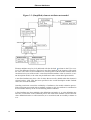
The family model (or family model) describes the solution family in terms of software architectural elements. Figure 3.5, “Basic structure of family models” shows the basic structure of family models as a UML class diagram. Both models are derived from the SolutionComponentModel class. The main difference between the two models is that family models contain variable elements guarded by restriction expressions. Since component models
are derived from family models and represent configured variants with resolved variabilities there are no restrictions used in component models.
Figure 3.5. Basic structure of family models
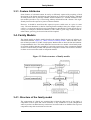
3.4.1. Structure of the family model
The components of a family are organized into a hierarchy that can be of any depth. A
component (with its parts and source elements) is only included in a result configuration
when its parent is included and any restrictions associated with it are fulfilled. For top-level
components only their restrictions are relevant.
17
Sample family model
Components:
A component is a named entity. Each component is hierarchically decomposed into further
components or into part elements that in turn are built from source elements.
Parts:
Parts are named and typed entities. Each part belongs to exactly one component and consists of any number of source elements.
A part can be an element of a programming language, such as a class or an object, but it
can also be any other key element of the internal or external structure of a component, for
example an interface description. pure::variants provides a number of predefined part
types, such as ps:class, ps:object, ps:flag, ps:classalias, and ps:variable. The family model
is open for extension, and so new part types may be introduced, depending on the needs of
the users.
Source elements:
Since parts are logical elements, they need a corresponding physical representation or representations. Source elements realise this physical representation. A source element is an
unnamed but typed element. The type of a source element is used to determine how the
source code for the specified element is generated. Different types of source elements are
supported, such as ps:file that simply copies a file from one place to a specified destination.
Some source elements are more sophisticated, for example, ps:classaliasfile, which allows
different classes with different (aliases) to be used at the same place in the class hierarchy.
The actual interpretation of source elements is the responsibility of the pure::variants transformation engine. To allow the introduction of custom source elements and generator rules,
pure::variants is able to host plug-ins for different transformation modules that interpret the
generated variant result model and produce a physical system representation from it.
The semantics of source element definitions are project, programming language, and/or
transformation-specific.
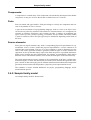
3.4.2. Sample family model
An example family model is shown below:
18
Sample family model
Figure 3.6. Sample family model
This model exhibits a hierarchical component structure. “System” is the top-level component, “Memory” its only a sub component. Inside this component are two parts, a class, and
a flag. The class is realized by two source elements. Selecting an element of the family
model will show its properties in the Properties view.
Using restrictions in Family Models:
A key capability that makes the family modelling language more powerful than other component description languages is its support of flexible rules for the inclusion of components, parts, and source elements. This is achieved by placing restrictions on each of these
elements.
Each element may have any number of restrictions. An element is included if its parent is
included and either there are no restrictions on it or at least one of its restrictions evaluates
to true.
For example, assigning the restriction not(hasFeature('Heap')) to the class
VoidEconomist in Figure 3.6, “Sample family model” will cause the class and its child
elements to be included when the feature Heap is not in the feature set of the variant. See
Section 3.4.3, “Restrictions in Family Models” for more information.
19
Restrictions in Family Models
3.4.3. Restrictions in Family Models
By default every element (component, part or source element) is included in a variant if its
parent element is included, or if it has no parent element. Restrictions specify conditions
under which a configuration element may be excluded from a configuration.
It is possible to put restrictions on any element, and on element properties and relations. An
arbitrary number of restrictions are allowed. Restrictions are evaluated in the order in
which they are listed. If a restriction rule evaluates to true, the restricted element will be included.
A restriction rule may contain arbitrary (Prolog) statements. The most useful rule is hasFeature(<feature name/id>) which evaluates to true if the feature selection contains the named feature.
Examples of Restriction Rules
Including an element only if a specific feature is present
hasFeature('Bar')
The element/attribute may be included only if the current feature selection contains the feature with identifier Bar.
Or-ing two restriction rules
Rule 1
not(hasFeature('BarFoos'))
Rule2
hasFeature('FoosBar')
This is a logical or of two statements. The element will be included if either feature BarFoos is not in the feature selection or FoosBar is in it.
It is also possible to merge both rules into one by using the or keyword.
Rule 1 or Rule 2
not(hasFeature('BarFoos')) or hasFeature('FoosBar')
3.4.4. Relations in Family Models
As for features, each element (component, part, and source element) may have relations to
other elements. The supported relations are described in Section 7.4, “Element Relations”.
When a configuration is checked, the configuration may be regarded as invalid if any relations are not satisfied.
20
Model Evaluation
Example using ps:exclusiveProvider/ps:requestsProvider relations
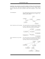
In the example below, the “Cosine” class element is given an additional
ps:requestsProvider relation to require that a cosine implementation must be present for a
configuration to be valid. ps:exclusiveProvider relation statements are used in two different
cosine implementations. Either of which could be used in some feature configurations
(feature FixedTime and feature Equidistant). But it cannot be both implementations in the
resulting system.
ps:class("Cosine")
Restriction: hasFeature('Cosine')
Relation:
ps:requestsProvider = 'Cosine'
ps:file(dir = src, file = cosine_1.cc, type = impl):
Restriction: hasFeature('FixedTime')
Relation:
ps:exclusiveProvider = 'Cosine'
ps:file(dir = src, file = cosine_2.cc, type = impl):
Restriction: hasFeature('FixedTime')
and hasFeature('Equidistant')
Relation:
ps:exclusiveProvider = 'Cosine'
Example for ps:defaultProvider/ps:expansionProvider relation
In the example given above an error message would be generated if the restrictions for both
elements were valid, as it would not be known which element to include. Below, this example is extended by using the ps:defaultProvider/ps:expansionProvider relations to
define a priority for deciding which of the two conflicting elements should be included.
These additional relation statements are used to mark the two cosine implementations as an
expansion point. The source element entry for cosine_1.cc specifies that this element
should only be included if no more-specific element can be included (ps:defaultProvider).
In this example, cosine_2.cc will be included when feature FixedTime and feature
Equidistant are both selected, otherwise the default implementation, cosine_1.cc is included. If the Auto Resolver for selection problems is activated then the appropriate implementation will be included automatically, otherwise an error message will highlight the
problem.
ps:class("Cosine")
Restriction: hasFeature('Cosine')
Relation:
ps:requestsProvider = 'Cosine'
ps:file(dir = src, file = cosine_1.cc, type = impl):
Restriction: hasFeature('FixedTime')
Relation:
ps:exclusiveProvider = 'Cosine'
Relation:
ps:defaultProvider = 'Cosine'
Relation:
ps:expansionProvider = 'Cosine'
ps:file(dir = src, file = cosine_2.cc, type = impl):
Restriction: hasFeature('FixedTime')
and hasFeature('Equidistant')
Relation:
ps:exclusiveProvider = 'Cosine'
Relation:
ps:expansionProvider = 'Cosine'
3.5. Model Evaluation
In the context of pure::variants, “model evaluation” is the activity of verifying that a variant description model (VDM) complies with the feature and family models it is related to.
Understanding this evaluation process is the key to a successful use of restrictions and relations.
21
Evaluation Algorithm
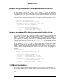
3.5.1. Evaluation Algorithm
An outline of the evaluation algorithm is given in pseudo code below Figure 3.7, “Model
Evaluation Algorithm (Pseudo Code)”.
Figure 3.7. Model Evaluation Algorithm (Pseudo Code)
modelEvaluation()
{
foreach(current in modelRanks())
{
checkAndStoreFeatSelection(
getFeatModelsByRank(current));
selectAndStoreFromFamModels(
getFamModelsByRank(current),class('ps:component'));
selectAndStoreFromFamilyModels(
getFamModelsByRank(current),class('ps:part'));
selectAndStoreFromFamilyModels(
getFamModelsByRank(current),class('ps:source'));
}
calculateAttributeValuesForResult();
checkFeatureRestrictions(getSelectedFeatures());
checkRelations();
checkConstraints();
}
The algorithm has certain implications on the availability of information in restrictions,
constraints, and attribute value calculations. For simplicity we will consider for now that
all feature and family models have the same model rank.
In the first evaluation step all feature selections stored in the VDM are matched to the
structure of their feature models. First all implicit features are calculated and merged with
the feature selected by the user. For this set it is now checked that structural rules for sub
feature selections are fulfilled. This means that it is checked that one alternative is selected
from an alternative feature group etc. Feature restrictions are not checked. This set of selected features is now stored for later access with “hasElement”.
The next step is to select elements from the family models. This is done in three iterations
through the model. In a first run all components are checked in a breadth-first-traversal
through the family model element hierarchy. For each component the restriction is evaluated. If the restriction evaluates to true, the respective component is added to the set of selected family model elements. When all components are checked, all child components of
the selected components are checked until no more child components are found. The set of
selected components is now stored for later access with “hasElement”. In the next run all
restrictions of child part elements of selected components are evaluated in the same way as
for components. The last run does this for all child parts of selected source elements. This
evaluation order permits part element restrictions to safely access the component configuration, since it will not change anymore. The drawback is that it is not safe to reason about
the component configuration in restrictions for components (of the same or lower ranks).
Warning
In pure::variants calling "hasElement" for an element of the same class (e.g.
'ps:component') and the same model rank will always yield 'false' as result.
Make sure that family model element restrictions are "safe". That is, they do
not contain directly or indirectly references to elements for which the selection
is not yet calculated (e.g. in attribute calculations or restrictions).
22
Automatic Selection Problem
Resolving
The above steps are repeated for all model ranks starting with the earliest model rank and
increasing to the latest model rank. (Note: the lower the model rank of a model, the earlier
it is evaluated in this process, e.g. a model of rank 1 is considered before a model of rank
2).
The last four steps in the model evaluation process are performed only once. First, the attribute values for all selected elements are calculated. Then the restrictions and after that
the relations of the selected features are checked. At this point all information about selected features and family model elements is available. Finally, the model constraints are evaluated deciding if the current selection is valid or not.
3.5.2. Automatic Selection Problem Resolving
If a feature selection is evaluated to be invalid, selection problems may be occured. Such
selection problems are for instance failed constraints or restrictions. Certain selection problems are eligible to be resolved automatically, e.g. a not yet selected feature that is required
by a relation can be selected automatically. pure::variants provides two levels of auto
resolving, i.e. basic and extended auto resolving.
The pure::variants basic auto resolver component provides resolving of failed relations and
feature selection ranges. Auto resolving of failed relations is for instance the automatic selection of required features. Auto resolving of failed feature selection ranges is for instance
the automatic selection of a feature of a group of features where at least one has to be selected.
The pure::variants extended auto resolver component additionally provides resolving of
failed restrictions and constraints. For instance if only a feature A is selected and there exists a constraint "A requires B" then feature B becomes automatically selected if the extended auto resolver is enabled.
Note
The auto resolver does not change the selection state of user selected or excluded features.
The auto resolving components are configured on the Auto Resolver tab of the Variant
Management->Model Handling preferences page (menu Window->Preferences).
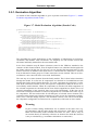
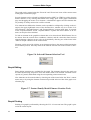
Auto resolving for a variant description model is enabled by pressing button
in the tool
bar. In Figure 3.8, “Automatically Resolved Feature Selections” a selection was auto resolved. The feature ABS was automatically selected due to the Requires relation on the
user selected feature ESP. The feature Electric was automatically selected because it is the
default feature of the alternative feature group Electric, Electrohydraulic, Hydraulic. The
icons for the different selection types are described in Section 7.9.1, “Feature Selection List
Entry Types”.
23
Model Transformation
Figure 3.8. Automatically Resolved Feature Selections
3.6. Model Transformation
pure::variants supports a user-specified generation of product variants using an XML-based
transformation component (XMLTS). XMLTS can process any kind of XML document by
binding processing modules onto the nodes of the XML document according to a userspecified module configuration. These processing modules encapsulate the actions to be
performed on a matching node in the XML document. A set of generic modules is supplied
with XMLTS, e.g. a module to execute XSLT scripts and a module for collecting and executing transformation actions. The user may create custom modules and integrate these
using the XMLTS module API.
The transformation module configuration is part of the configuration space properties (see
Section 5.3.6, “Configuration Space Editor”).
3.6.1. The Transformation Process
The XMLTS transformation process works by traversing the XML document tree. Each
node visited during this traversal is checked to see whether any processing modules should
be executed on it. If no module has to be executed, then the node is skipped. Otherwise the
actions of each module are performed on the node. Further modules executed on the node
can process not only the node itself but also the results produced by previously invoked
modules.
The processing modules to be executed are defined in a module configuration file. This file
lists the applicable modules and includes configuration information for each module such
as the types of nodes on which a module is to be invoked. The transformation engine evaluates this configuration information before the transformation process is started.
24
pure::variants Transformation Input
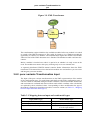
Figure 3.9. XML Transformer
The transformation engine initializes the available modules before any module is invoked
on a node of the XML document tree. This could, for instance, give a database module the
opportunity to connect to a database. The transformation engine also informs each module
when traversal of the XML document tree is finished. The database module could now disconnect.
Before a module is invoked on a node it is queried as to whether it is ready to run on the
node. The module must answer this query referring only on its own internal state.
A separately distributed XMLTS manual contains further information about the XML
transformer. This manual shows how the built-in modules are used and how you can create
and integrate your own modules.
3.6.2. pure::variants Transformation Input
The input of the pure::variants transformation are the XML representations of the models
of the configuration space. For each feature and family model of the configuration space a
concrete variant is calculated during the model evaluation, called result model. Restrictions
and constraints are evaluated and removed from result models. Attribute value calculations
are replaced by their calculated values. Corresponding to these modifications the type of
the models is changed to signal that a model is a concrete variant (see Table 3.1, “Mapping
between input and result model types”).
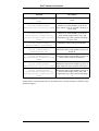
Table 3.1. Mapping between input and result model types
Input Model Type
ps:fm (Feature Model)
ps:ccfm (Family Model)
ps:vdm (Variant Description Model)
Result Model Type
ps:cfm (Concrete Feature Model)
ps:ccm (Concrete Family Model)
ps:vdm (Variant Description Model, identical to the input model)
25
Model Validation
For the transformation the result models and additional variant information are collected in
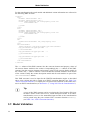
the following XML structure.
<variant>
<cfl>
<element idref="element id"/>
<novalue idref="property id"/>
<value idref="property id" vid="property value id"
eid="element id">
...
</value>
...
</cfl>
<ccl>
<element idref="element id"/>
<novalue idref="property id"/>
<value idref="property id" vid="property value id"
eid="element id">
...
</value>
...
</ccl>
<il>
<inherited eid="element id" pid="property id"/>
...
</il>
<cm:consulmodels
xmlns:cm="http://www.pure-systems.com/consul/model">
<cm:consulmodel cm:type="ps:vdm" ...>
...
</cm:consulmodel>
<cm:consulmodel cm:type="ps:cfm" ...>
...
</cm:consulmodel>
...
<cm:consulmodel cm:type="ps:ccm" ...>
...
</cm:consulmodel>
...
</cm:consulmodels>
</variant>
The cfl subtree of this XML structure lists the concrete elements and property values of
all concrete feature models in the variant. Correspondingly the ccl subtree of this XML
structure lists the concrete elements and property values of all concrete family models in
the variant. The il subtree contains a list of all inherited element attributes in all models
of the variant. Finally the variant description model and all result models are part of the
cm:consulmodels subtree.
This XML structure is used as input for the XMLTS transformation engine as described
above. pure::variants provides a certain set of XSLT extension functions (see Table 7.20,
“XSLT extension functions”) to simplify the navigation and evaluation of this XML structure in an XSLT transformation (see Section 4.1.2, “Using XSLT for the Transformation”).
Tip
A copy of this XML structure can be saved using the "Save Result to File" button that is shown in the tool bar of a variant description model. In an XSLT
transformation, access to the unmodified input models of the transformation
can be gained using the pure::variants XSLT extension function models()
(see Table 7.20, “XSLT extension functions”).
3.7. Model Validation
26
XML Schema Model Validation
In the context of pure::variants, “model validation” is the process of checking the validity
of feature, family, and variant description models. Two kinds of model validation are supported, i.e. validating the XML structure of models using a corresponding XML Schema
and performing a configurable set of checks using the model check framework.
3.7.1. XML Schema Model Validation
This model validation uses an XML Schema to check if the XML structure of a
pure::variants model is correct. This is pure syntax check, no further analyses of the model
are performed.
The XML Schema model validation is disabled per default. It can be enabled selecting option "Validate XML structure of models..." on the Variant Management->Model Handling
preferences page (menu Window->Preferences). If enabled all pure::variants models are
validated when opened.
Note
Invalid models will not be opened correctly if the XML Schema model validation is enabled.
For more information about XML Schemas see the W3C XML Schema Documentation.
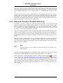
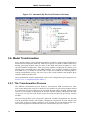
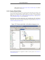
3.7.2. Model Check Framework
The model check framework allows the validation of models using a configurable and extensible set of rules (called "model checks"). There are no restrictions on the complexity of
model checks.
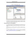
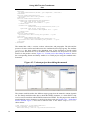
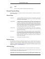
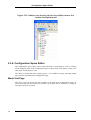
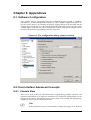
Configuring the Framework
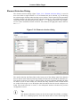
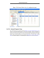
The model check framework is configured on the Variant Management->Model Validation
preference page (menu Window->Preferences). In this page model check configurations
can be managed and activated (see Figure 3.10, “Model Validation Preferences Page”).
27
Model Check Framework
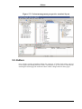
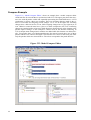
Figure 3.10. Model Validation Preferences Page
The two default configurations "All Model Checks" and "All Element Checks" are always
available. "All Model Checks" contains all model checks that perform whole model analyses. Compared with "All Element Checks" containing all checks that perform analyses on
element level. The configuration "All Element Checks" is enabled per default if the
pure::variants perspective is opened the first time.
A model check configuration is activated by selecting it in the "Available Configurations"
list. If more than one configuration is selected, the checks from all selected configurations
are merged into one set that becomes activated.
The checks contained in a configuration are shown in the "Selected Configuration" list by
clicking on the name of the configuration. The checks are listed by its names followed by
the list of model types supported by a check. Additionally the icon
reveals if the check
is enabled for automatic model validation (see the section called “Performing Model
Checks”). A brief description of a check is shown by moving the mouse pointer over the
check name.
All but the two default configurations "All Model Checks" and "All Element Checks" can
be deleted by clicking first on the name of the configuration and then on button "Delete".
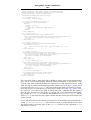
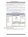
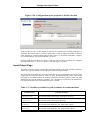
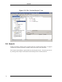
A new configuration can be created by clicking on the "New" button. This will open the
New Check Configuration dialog as shown in Figure 3.11, “New Check Configuration
Dialog”.
28
Model Check Framework
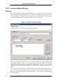
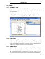
Figure 3.11. New Check Configuration Dialog
For a new check configuration a unique name for the configuration has to be entered. The
available checks are shown in the "Available Checks" tree and can be selected for the new
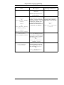
configuration by clicking on the check boxes of the checks. Clicking on the root of a subtree selects/deselects all checks of this sub-tree.
Detailed information about a check are displayed in the Check Details area of the dialog if
the name of a check is selected. The Model Types field shows the list of model types for
which the corresponding check is applicable. The Description field shows the description
of the check. And with the "Enable check for..." button (or clicking on the icon
of a
check) it can be configured whether a check is performed during automatic model validation (see the section called “Performing Model Checks”).
The same dialog appears for editing and copying check configurations using the "Edit" and
"Copy" buttons. Only non-default configurations can be edited.
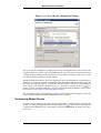
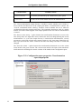
Performing Model Checks
A model can be checked using the selected model check configurations by opening the
model in a corresponding model editor and pressing button in the tool bar. This will start
a single model validation cycle. The progress of the model validation is shown in the Progress view.
29
Model Check Framework
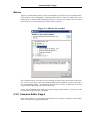
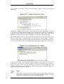
Figure 3.12. Model Validation in Progress
If no model check configuration is selected a dialog is opened inviting the user to choose a
non-empty check configuration. This dialog can be disabled by enabling the "Do not show
again" check box of the dialog.
The button
is used to enable automatic model checking, i.e. after every change on the
model a new check cycle is started automatically. In contrast to the single model validation
cycle only those checks are performed that are enabled for automatic model validation.
The result of a model check cycle is a list of problems found in the model. These problems
are shown in the Problems view and as markers on the model. A list of quick fixes for a
problem can be shown either by choosing "Quick Fix" from the context menu of the problem in the Problems view or by clicking on the corresponding marker on the model. For
some problems special quick fixes are provided fixing all problems of the same kind.
30
Chapter 4. Tasks
4.1. Generating Variants with Model Transformations
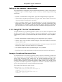
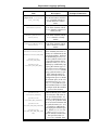
4.1.1. Using the Standard Transformation
The standard transformation is suitable for many projects, such as those with mostly filerelated actions for creating a product variant. This transformation also includes some special support for C/C++-related variability mechanisms like preprocessor directives and creation of other C/C++ language constructs.
The standard transformation is based on a type model describing the available element
types for family models (see Figure 4.1, “The Standard Transformation Type Model”).
First a corresponding transformation module converts the variant result model containing
standard transformation elements into an action list. In a second transformation step this
action list is executed by the action list processor (also a transformation module).
Figure 4.1. The Standard Transformation Type Model
The standard transformation supports a rich set of source elements for file-oriented variant
generation. Source elements can be combined with any part element (and also with part
types which are not from the set of standard transformation part types) unless otherwise
noted. For a detailed description of the standard transformation relevant source element
types see Section 7.8.1, “Predefined Source Element Types”.
31
Using the Standard Transformation
The supported part element types are intended to capture the typical logical structure of
procedural (ps:function, ps:functionimpl) and object-oriented programs (ps:class,
ps:object, ps:method, ps:operator, ps:classalias). Some general purpose types like
ps:project, ps:link, ps:aspect, ps:flag, ps:variable, ps:value or ps:feature are also available.
For a detailed description of the standard transformation relevant part element types see
Section 7.8.2, “Predefined Part Element Types”.
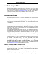
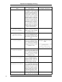
Assigning values to part elements
Some of the part element types have a mandatory attribute Value. The value of this attribute is used by child source elements of the part, for example to determine the value of a C
preprocessor #define generated by a ps:flagfile source element. Unless noted otherwise
any part element with an attribute Value can be combined with any source element using
an attribute Value. For example, it is possible to use a ps:value part with ps:flagfile and
ps:makefile source elements to generate the same value into both a makefile and a preprocessor #define in some header file.
Calculation of the value of a ps:flag or ps:variable part element is based on the
value of attribute Value. The value may be a constant or calculation. There may be more
than one attribute Value defined on a part with maybe more than one value guarded by restrictions. The attributes and its values are evaluated in the order in which they are listed in
the Attributes page of the element's Properties dialog. The first attribute resp. attribute
value with a valid restriction that evaluates to true or without a restriction is used.
Figure 4.2, “Multiple attribute definitions for Value calculation” shows typical Value attribute definitions. The value 1 is restricted and only set under certain conditions. Otherwise the unrestricted value 0 is used.
Figure 4.2. Multiple attribute definitions for Value calculation
32
Using XSLT for the Transformation
Setting up the Standard Transformation
The transformation configuration for the standard transformation is either created when a
configuration space is created using the wizard, or can be (re-)created using the following
instructions:
• Open the “Transformation Configuration” page in the configuration space properties.
• Add the module “Standard transformation” using the “Add” button. Name it for instance
“Generate Standard Transformation Actionlist”.
• Add an "Actionlist" module. Leave the include pattern as “/variant” and all other parameters empty. Name it for instance “Execute Actionlist”. In normal circumstances there
should be only one "Actionlist" module for an include pattern, otherwise the action list
gets executed twice on a tree node (for each action list module matching the same node).
4.1.2. Using XSLT for the Transformation
A highly flexible way of generating product variants is to use XSLT in conjunction with
the pure::variants XSLT extension functions. No special requirements are placed on the
transformation you have to perform and using the extension functions is quite straightforward:
• Open the transformation configuration page in the configuration space properties.
• Add the “XSLT script execution” module using the “Add” button. Name it for instance
“Execute XSLT script”.
• Change the module parameters page by pressing “Next” and enter the name of the XSLT
script file you want to execute as value of the “in” parameter.
• An (optional) output file can be specified using the “out” parameter.
• Press Finish to close the transformation configuration page and start the transformation.
Example: Conditional Document Parts
To demonstrate how to use XSLT to generate a product variant, the following example will
show the generation of a manual in HTML format with different content for different target
groups (users, developers). This example uses the standard transformation and a userprovided XSLT script implementing a lite version of the ps:condxml source element functionality. The basic idea is to represent the manual in XML and then to use an XSLT script
to generate the HTML representation. Attributes on the nodes of the XML document are
used to discriminate between content for different target groups.
The example XML document looks like this:
<?xml version="1.0" encoding="UTF-8"?>
<document>
<title condition="pv:hasFeature('developer')">
<par>Developer Manual</par>
</title>
<title condition="pv:hasFeature('user')">
<par>User Manual</par>
</title>
33
Using XSLT for the Transformation
<version>
pv:getAttributeValue('build','ps:component','version')
</version>
<section name="Introduction">
<par>Some text about the product...</par>
</section>
<section name="Installation">
<subsection name="Runtime Environment">
<par>Some text about installing
the runtime environment...</par>
</subsection>
<subsection name="SDK"
condition="not(pv:hasFeature('user'))">
<par>Some text about installing
the software development kit...</par>
</subsection>
</section>
<section name="Usage">
<par>Some text about using the product...</par>
</section>
<section name="Extension API"
condition="pv:hasFeature('developer')">
<par>Some text about extending the product...</par>
</section>
</document>
The manual has a title, a version, sections, subsections, and paragraphs. The title and the
presence of some sections and subsections are conditional on the target group. The attribute
condition has been added to the dependent parts of the document to decide which
part(s) of the document are to be included. These conditions test the presence of certain
features in the product variant. Figure 4.3, “Variant project describing the manual” shows
the corresponding feature and family models in a variant project using the standard transformation.
Figure 4.3. Variant project describing the manual
The feature model describes the different target groups that the manual's content depends
on. The family model describes how to build the HTML document, i.e. which XSLT script
is to be used to transform which XML document into HTML. For this purpose the standard
transformation source element ps:transform has been used (see Section 7.8.1, “Predefined
Source Element Types”). This source element refers to the XSLT script build.xsl
shown below:
<?xml version="1.0" encoding="UTF-8"?>
<xsl:stylesheet version="1.0"
xmlns:xsl="http://www.w3.org/1999/XSL/Transform"
34
Using XSLT for the Transformation
xmlns:pv="http://www.pure-systems.com/purevariants"
xmlns:cm="http://www.pure-systems.com/consul/model"
xmlns:dyn="http://exslt.org/dynamic"
extension-element-prefixes="pv dyn">
<!-- generate text -->
<xsl:output method="html"/>
<!-- match document root node -->
<xsl:template match="document">
<html>
<title></title>
<body>
<xsl:apply-templates mode="body"/>
</body>
</html>
</xsl:template>
<!-- match title -->
<xsl:template match="title" mode="body">
<xsl:if test="not(@condition) or dyn:evaluate(@condition)">
<h1><xsl:apply-templates mode="body"/></h1>
</xsl:if>
</xsl:template>
<!-- match version -->
<xsl:template match="version" mode="body">
<p><b><xsl:value-of
select="concat('Version:',dyn:evaluate(.))"/></b>
</p>
</xsl:template>
<!-- match section -->
<xsl:template match="section" mode="body">
<xsl:if test="not(@condition) or dyn:evaluate(@condition)">
<h2><xsl:value-of select="@name"/></h2>
<xsl:apply-templates mode="body"/>
</xsl:if>
</xsl:template>
<!-- match subsection -->
<xsl:template match="subsection" mode="body">
<xsl:if test="not(@condition) or dyn:evaluate(@condition)">
<h4><xsl:value-of select="@name"/></h4>
<xsl:apply-templates mode="body"/>
</xsl:if>
</xsl:template>
<!-- match paragraphs -->
<xsl:template match="par" mode="body">
<p><xsl:value-of select="."/></p>
</xsl:template>
</xsl:stylesheet>
The script takes XML as input and produces HTML as output. It has several transformation
parts, one for every manual element, where the condition attributes are dynamically evaluated. Note that these condition attributes are expected to be valid XPath expressions. In the
XML description of the manual these expressions contain calls to the pure::variants XSLT
extension function hasFeature(), this expects the unique name of a feature as an argument and returns true if this feature is in the product variant (see Table 7.20, “XSLT extension functions”). If a node of the XML document has such a condition and this condition
fails, the node and all of its child nodes are ignored and are not transformed into HTML.
For example, if a <section> node has the condition hasFeature('user') and the
feature user is not selected in the product variant, then this section and all its subsections
will be ignored.
In the XML description of the manual a second pure::variants XSLT extension function is
called, getAttributeValue(). This function is used to get the manual version from
the family model. It reads the value of the version attribute of the component build
and returns it as string.
35
Using XSLT for the Transformation
Figure 4.4, “The manual for users and developers” shows the two variants of the manual
(HTML) generated selecting target group user and then developer.
Figure 4.4. The manual for users and developers
36
Chapter 5. Graphical User Interface
The layout and usage of the pure::variants User Interface closely follows Eclipse
guidelines. See the Workbench User Guide provided with Eclipse (“Help”->”Help Contents”) for more information on this.
5.1. Getting Started with Eclipse
This section gives a short introduction to the elements of the Eclipse UI before introducing
the pure::variants UI. Readers with Eclipse experience may skip this section.
Eclipse is based around the concepts of workspaces and projects. Workspaces are used by
Eclipse to refer to enclosed projects, preferences and other kinds of meta-data. A user may
have any number of workspaces for different purposes. Outside of Eclipse, workspaces are
represented as a directory in the file system with a subdirectory .meta-data where all workspace-related information is stored. A workspace may only be used by a single Eclipse instance at a time. Projects are structures for representing a related set of resources (e.g. the
source code of a library or application). The contents and structure of a project depends on
the nature of the project. A project may have more than one nature. For example, Java
projects have a Java nature in addition to any project-specific natures they may have.
Natures are used by Eclipse to determine the type of the project and to provide specialised
behaviour. Project-specific meta information is stored in a .project file inside the project
directory. This directory could be located anywhere in the file system, but projects are often placed inside a workspace directory. Projects may be used in more than one workspace
by importing them using (“File”->“Import”->”Import Existing Project”).
Figure 5.1, “Eclipse workbench elements” shows an Eclipse workbench window. A perspective determines the layout of this window. A perspective is a (preconfigured) collection of menu items, toolbar entries and sub-windows (views and editors). For instance this
figure shows the standard layout of the Resource perspective. Perspectives are designed for
performing a specific set of tasks (e.g. the Java perspective is used for developing Java programs). Users may change the layout of a perspective according to their needs by placing
views or editors in different locations, by adding or closing views or editors, menu items
and so on. These custom layouts may be saved as new perspectives and reopened later. The
standard layout of a perspective may be restored using “Window”->”Reset Perspective”.
Editors represent resources, such as files, that are in the process of being changed by the
user. A single resource cannot be open in more than one editor at a time. A resource is normally opened by double-clicking on it in a Navigator view or by using a context menu.
When there are several suitable editors for a given resource type the context menu allows
the desired one to be chosen. The figure below shows some of the main User Interface elements:
37
Variant Management Perspective
Figure 5.1. Eclipse workbench elements
Eclipse uses Views to represent any kind of information. Despite their name, data in some
types of view may be changed. Only one instance of a specific type of view, such as the
Outline view, may be shown in the workbench at a time. All available views are accessible
via Windows->Show View->Other.
5.2. Variant Management Perspective
pure::variants adds a Variant Management perspective to Eclipse to provide comprehensive
support for variant management. This perspective is opened using “Window->Open Perspective->Other->Variant Management”. Figure 5.2, “Variant management perspective
standard layout” shows this perspective with a sample project.
38
Editors
Figure 5.2. Variant management perspective standard layout
5.3. Editors
pure::variants provides specialized editors for each type of model. Each editor can have
several pages representing different model visualizations (e.g. tree-based or table-based).
Selecting the desired page tab within the editor window changes between these pages.
39
Common Editor Actions
5.3.1. Common Editor Actions
Filtering
Most views and editors support filtering. Depending on the type of view, the filtered elements are either not shown (table like views) or shown in a different style (tree views). Filters can be defined, or cleared, from the context menu of the respective view/editor page.
When the view/editor has several pages the filter is active for all pages.
Figure 5.3. Filter definition dialog
Arbitrarily complex filters based on comparison operations between feature/element properties (name, attribute values, etc.) and logical expressions (and/or/not) are supported.
Comparison operations include conditions like equality and containment, regular expressions (matches) and checks for the existence of an attribute for a given element (empty/not
empty).
Filters can be named for later reuse using the Named Filter field. The drop-down box allows access to previously defined filters. Fast access to named filters is provided by the
Filter view, which can be activated using the Windows->Views->Other->Variant Management->Filter item.
40
Common Editor Pages
Metrics
All pure::variants model editors provide an extensible set of metrics for the opened models.
These metrics can be displayed by choosing "Show Metrics" from the context menu of a
model editor. If metrics shall be displayed only for a sub-tree of a model, the root of this
sub-tree has to be selected before the context menu is opened.
Figure 5.4. Metrics for a model
The available metrics are listed in a tree showing the name and overall results of the metrics on top level. Partial results and detailed information provided by a metric are listed in
the corresponding subtree. An explaining description of a metric is displayed in the Description field if the name of the metric is marked.
On the Variant Management->Metrics preferences page (menu Window->Preferences), the
set of metrics to apply can be configured.
5.3.2. Common Editor Pages
Since most models are represented as hierarchical tree structures, different model editors
share a common set of pages and dialogs.
41
Common Editor Pages
Tree Editing Page
The tree-editing page shows the model in a tree-like fashion (like Windows Explorer). This
page allows multiple-selection of elements and supports drag and drop. Tree nodes can
also be cut, copied, and pasted using the global keyboard shortcuts (see Section 7.2,
“Keyboard Shortcuts”) or via a context menu.
Selection of a tree node causes other views to be updated, for instance the Properties view.
Conversely, some views also propagate changes in selection back to the editor (e.g. the
outline views).
A context menu enables the expansion or collapse of all children of a node.
Double-clicking on a node opens a property dialog for that node.
Table View/Editor Page
The table view is available in many views and editors. This view is a tabular representation
of the tree nodes. The visible columns and also the position and width of the columns can
be customized via a context menu (Table Layout->Change). Layout changes for each model are stored permanently in the Eclipse workspace. Clicking on a column header sorts that
column. The sort direction may be reversed with a second click on the same column header.
Tip
Double clicking on a column header separator adjusts the column width to
match the maximal width required to completely show all cells of that column.
Most cells in table views are directly editable. A single-click into a cell selects the row; a
second click opens the cell editor for the selected cell. The context menu for a row permits
addition of new elements or deletion of the row. A double-click on a row starts a property
dialog for the element associated with the row.
Constraints Editing Page
The Constraints page is available in the feature and family model editor and shows all constraints in the current model. Constraints can be edited or new created on this page. It also
supports to change the element defining a constraint.
Figure 5.5, “Constraints view” shows the Constraints page containing two constraints formulated in pvSCL. The first column in the table of the page contains the name of the constraint. The constraint expression is shown in the second column. In column three the type
of the element defining the constraint is shown. The defining element itself is shown in the
last column.
42
Common Editor Pages
Figure 5.5. Constraints view
New constraints can be added by pressing button "New". The name of a constraint can be
changed by double-clicking into the name field of the constraint and entering the new name
in the opened cell editor. Double-clicking into the "Defining Element" column of a constraint opens an element selection dialog allowing the user to change the defining element.
Clicking on a constraint shows the constraint expression in the editor in the bottom half of
the page. The kind of editor depends on the language in which the constraint is formulated
(see the section called “Advanced Expression Editor” for more information about the editor). The language for the constraint expression can be changed by choosing a different language from the "Language" list button.
Changes to constraints are applied using the "Apply" button and discarded using the "Restore" button.
Graph Visualization Page
The graph visualization page is primarily intended for the graphical representation and
printing of models. Although the usual model editing operations like copy, cut, and paste
and the addition, editing, and deletion of model elements also are supported.
43
Common Editor Pages
Note
The graph visualization is only available if the Graphical Editing Framework
(GEF) is installed in the Eclipse running pure::variants. More information
about GEF are available on the GEF Home Page.
For nearly all actions on a graph that are explained in the next sections keyboard shortcuts
are available listed in Section 7.2, “Keyboard Shortcuts”.
Graph Elements
Model elements are represented in the graph as boxes containing the name of the element
and an associated icon. Feature model elements are represented as shown in the next figure.
The representation of family model elements slightly differs for part and source elements.
Parent-child relations are visualized by arrows between the parent and child elements.
Other relations are visualized using colored connection lines between the related elements.
The color of the connection line depends on the relation and matches the color that is used
for this relation on the tree editing page.
If an element has children a triangle is shown in the upper right-hand corner of the element
box. Depending on whether the element is collapsed or expanded a red or white corner is
shown.
Graph Layout
The layout of the graph can be changed in several ways. Graph elements can be moved, expanded, collapsed, hidden, and automatically aligned. The graph can be zoomed and the
layout of the connections between the elements of the graph can be changed.
Two automatic graph layouts are supported, i.e. horizontal aligned and vertical aligned.
Choosing "Layout Horizontal" from the context menu of the graph visualization page automatically layouts the elements of the graph from left to right. The elements are layouted
from top to bottom choosing "Layout Vertical" from the context menu.
44
Common Editor Pages
Depending on the complexity of a graph the default positioning of the connection lines
between the elements of the graph may not be optimal, e.g. the lines overlap or elements
are covered by lines. This may be changed by choosing one of three available docking
rules for connection lines from the submenu "Select Node Orientation" of the context
menu.
No Docking Rule
The connection lines point to the center of connected
elements. Thus connection lines can appear everywhere around an element.
Dock Connections on Left or Right
The connection lines are positioned in the middle of
the left or right side of connected elements. This is
especially useful for horizontally layouted graphs.
Dock Connections on Top or Bottom
The connection lines are positioned in the middle of
the top or bottom side of connected elements. This is
especially useful for vertically layouted graphs.
45
Common Editor Pages
The graph can be zoomed using the "Zoom In" and "Zoom Out" items of the context menu
of the graph visualization page.
Several elements can be selected by holding down the SHIFT or STRG key while selecting
further elements, or by clicking somewhere in the empty space of the graph visualization
page and dragging the mouse over elements. A dashed line appears and all elements that
are partially or wholly enclosed in it will be selected.
If an element has children the element can be expanded or collapsed by clicking on the triangle in the upper right-hand corner of the element's box. Another way is to use the "Collapse Element", "Expand Element", and "Expand Subtree" context menu items. In contrast
to the "Expand Element" action, "Expand Subtree" expands the whole subtree of an element, not only the direct children.
To hide an element in the graph this element has to be selected and "Hide Element" has to
be chosen from the context menu. Attributes, relations, and the connection lines between
related elements (relations arrows) also can be hidden by choosing one of the items in the
"Show In Graph" submenu of the context menu.
Elements can be moved by clicking on an element and move the mouse while keeping the
mouse button pressed. This only works if the element selection tool in the tool bar is selected.
Figure 5.6. Selected Element Selection Tool
Graph Editing
Basic editing operations are available for the graph. The elements shown in the graph can
be edited by choosing "Properties" from the context menu of an element. Elements can be
copied, cut, pasted, and deleted using the corresponding context menu items.
New elements can be created either by choosing one of the items below the "New" context
menu entry or by using the element creation tool provided in the tool bar of the graph visualization page.
Figure 5.7. Feature/Family Model Element Creation Tools
Graph Printing
Printing of a graph is performed by choosing the File->Print menu item. The graph is printed in the current layout.
46
Common Editor Pages
Note
Printing is only available on Windows operating systems.
Element Property Dialog
The property dialog for an element contains a General, Relations, Attributes, Restrictions,
and Constraints page.
General Page
Unique ID
A unique identifier for the model element. This identifier is generated
automatically and cannot be changed. Every feature model element
has to have a unique identifier.
Unique Name
A unique name for the model element. The name must not begin with
a numeric character and must not contain spaces. The uniqueness of
the name is automatically checked against other elements of the same
model. The unique name can be used to identify elements instead of
their unique identifier. Unique names are required for each feature, but
not for other model elements. The Unique name is displayed by default (in brackets if the visible name is also displayed).
Visible Name
An informal name for the model element. This name is displayed in
views by default. This name can be composed of any characters and
doesn't have to be unique.
Class/Type
The class and type of the model element. In feature models elements
can only have class ps:feature. Thus the element class for features cannot be changed. Elements in family models can have one the following
classes: ps:component, ps:part, or ps:source. The root element of a
family model always has the class ps:family. The type of a model element is freely selectable.
Description
A description of the model element.
Relations Page
This page allows definition of additional relations between an element and other elements,
such as features or components. Typical relations between features, such as requires or
conflicts, can be expressed using a number of built-in relationship types. The user may also
extend the available relationship types. More information on element relations can be
found in Section 3.2.3, “Element Relations”.
Attributes Page
Every element may have an unlimited number of associated attributes (name-value pairs).
The attributes page uses a table of trees to visualize the attribute declaration (root row) and
(optional) attribute value definitions (child rows).
Each attribute has an associated Type and may have any number of Value definitions associated with it. The values must be of the specified Type. The number of attribute value
47
Common Editor Pages
definitions is shown in the “#” column. In the example in Figure 5.8, “Sample attribute
definitions for a feature”, the attribute DemoAttribute has two value definitions (1 and 0).
Figure 5.8. Sample attribute definitions for a feature
Attributes can be inherited from parent elements. Checking the inheritable cell (column
icon ) in the parent elements Attribute page does this. An inherited attribute may be overridden in a child element by defining a new attribute with the same name as the inherited
attribute. The new attribute may or may not be inheritable as required.
Attributes can be fixed by checking the cell in the
column. Fixed attributes are calculated from value definitions in the model in which they are declared, in contrast to nonfixed attributes for which the value is specified in a variant description model. Default values can be (optionally) defined here for non-fixed attributes. These are used if no value is
specified in the variant description model.
An attribute may have a restricted availability. This is indicated by a check mark in the
column. Clicking on a cell in this column activates the Restrictions editor. To restrict the
complete attribute definition use the restriction cell in the attribute declaration (root) row.
To restrict an attribute value, expand the attribute tree and click into the restriction cell of
the value. Restrictions can either be entered directly into a cell or by using the Restrictions
editor. Clicking on the button marked ... which appears in the cell when it is being edited
also opens this editor. See the section called “Restrictions Page” for detailed information.
During model evaluation, attribute values are calculated in the listed order. The Move Up
and Move Down buttons on the right side of the page can be used to change this order. The
first definition with a valid restriction (if any) and a constant, or a valid calculation result,
defines the resulting attribute value.
48
Common Editor Pages
Values can be entered directly into a cell or by using the Value editor. Clicking on the button marked ..., which appears in the cell when it is being edited, opens this editor. The editor also allows the value definition type to be switched between constant and calculation.
The calculation type can use the pvProlog language to provide more complex value definitions. More information on calculating attribute values is given in the section called
“Attribute Value Calculations with pvProlog”.
The use of attributes is covered further in Section 3.2.3, “Element Relations”.
Restrictions Page
The Restrictions page defines element restrictions. Any element that can have restrictions
can have any number of them. A new restriction can be created using the Add button; an
existing restriction can be removed using Remove. The order of restrictions may be
changed using the Move Up and Move Down buttons on the right side of the page.
Figure 5.9. Restrictions page shown in property editor
A restriction can be edited in place using the cell editor (shown in the right side of figure
Figure 5.9, “Restrictions page shown in property editor”). Note the difference in restriction
#1 in the left and right sides of the figure. Unless they are being edited, the element identifiers in restrictions are shown as their respective unique names (e.g. 'Garlic') when available. When the editor is opened the actual restriction is shown (e.g. 'i6o.../...rusL'), and no
element identifier substitution takes place. The ... button opens an advanced editor that is
more suitable for complex restrictions. This editor is described more detailed in the section
called “Advanced Expression Editor”.
Constraints Page
The Constraints page defines model constraints. Any element that can have constraints can
have any number of them. A new constraint can be created using the Add button. An existing constraint can be removed using Remove. The order of constraints may be changed using the Move Up and Move Down buttons on the right side of the page. This has no effect
on whether a constraint is evaluated or not; constraints are always evaluated.
49
Common Editor Pages
Figure 5.10. Constraints page shown in property editor
For each constraint a descriptive name can be specified. It has no further meaning other
than a short description of what the constraint checks. A constraint can be edited in place
using the cell editor (shown in the right side of figure Figure 5.10, “Constraints page
shown in property editor”). The ... button opens an advanced editor dialog that is more suitable for complex constraints. This editor is described more detailed in the section called
“Advanced Expression Editor”.
Advanced Expression Editor
The advanced expression editor is used everywhere in pure::variants where more complex
expressions may be inserted. This is for instance when writing more complex restrictions,
constraints, or calculations.
Currently it supports the two languages pvProlog and pvSCL. Special editors are available
for both languages. Figure 5.11, “Advanced pvSCL expression editor” shows the pvSCL
editor editing a constraint.
50
Common Editor Pages
Figure 5.11. Advanced pvSCL expression editor
This dialog supports syntax highlighting for pvSCL keywords and auto completion for
identifiers. There are two forms of completion. Pressing CTRL+SPACE while typing in
an identifier opens a list with matching model elements and pvSCL keywords as shown in
the figure. If the user enters "<ModelName>." or "@<ModelId>/" a list with the elements
of the model is opened automatically. There is always a special entry at the end of such a
list, "Open Element Selection Dialog...", which opens the Element Selection dialog supporting better element selection. This dialog is described more detailed in the section called
“Element Selection Dialog”.
Warning
The pvSCL syntax is not checked in this editor. A syntactically wrong expression will cause the model evaluation to fail.
Figure 5.12, “Advanced pvProlog expression editor” shows the pvProlog editor directly
editing a constraint expression.
51
Common Editor Pages
Figure 5.12. Advanced pvProlog expression editor
Pressing CTRL+SPACE in this editor opens the element selection dialog. All element
identifiers selected in this dialog are inserted into the expression as quoted strings. This
dialog is described more detailed in the section called “Element Selection Dialog”.
Warning
The pvProlog syntax is not checked in this editor. A syntactically wrong expression will cause the model evaluation to fail.
Figure 5.13, “pvProlog expression pilot” shows the pvProlog editor editing a constraint in
the expression pilot. In constrast to the pvProlog source editor the pilot always produces
syntactically correct pvProlog code.
52
Common Editor Pages
Figure 5.13. pvProlog expression pilot
A pvProlog function can be inserted into the expression by pressing on button "New" or
choosing Add->New from the context menu. The inserted function can be changed by
choosing another function in field "Operator". The argument of the function is added by
pressing on button "..." next to field "Value". If the check button "Use Unique Name" is
checked, the unique name of the selected element is inserted as argument. Otherwise the id
of the selected element is inserted.
An operator can be added by choosing the corresponding operator from the Add context
menu entry. To change an operator the context menu entry "Change to" is used. The "Negate" button adds a "NOT" operator on top of the selected function or operator.
A selected function or operator can be removed by pressing button "Remove". The "Move
up" and "Move down" buttons are used to move operands up or down (for instance to swap
operands).
The resulting pvProlog source code for the constructed expression is shown in the bottom
half of the editor.
53
Common Editor Pages
Element Selection Dialog
The element selection dialog (figure Figure 5.14, “Element selection dialog”) is used in
most cases when a single element or a set of elements has to be selected, e.g. for choosing
the relation target elements when inserting a new relation. The left pane lists the potentially
available elements, the right pane lists the selected elements. To select additional elements,
select them in the left pane and press the button “==>”. Multiple selection is also supported. To remove elements from the selection, select them in the right pane and use the button “<==”.
Figure 5.14. Element selection dialog
The model selection and filter fields in the lower part of the dialog control the elements
that are shown in the left Label field. By default, all elements for all models within the current project are shown. If a filter is selected, then only those elements matching the filter
are shown. If one or more models are selected, then only elements of the selected models
are visible. If the scope is set to Workspace then all models from the current workspace are
listed. The model selection is stored, so for subsequent element selections the previous
configuration is used.
Tip
The element information shown in the left and right Label fields is configurable. Use “column properties” from the context menu to select and arrange the
54
Feature Model Editor
visible columns. See the section called “Table View/Editor Page” for additional information on table views.
5.3.3. Feature Model Editor
Every open Feature model is shown in a separate Feature model editor tab in Eclipse. This
editor is used to add new features, to change features, or to remove features. Variant configuration is not possible using this editor. Instead, this is done in a variant description
model editor (see Section 5.3.5, “Variant Description Model Editor” and Section 2.6,
“Using Configuration Spaces” for more information).
The default page of a feature model editor is the tree-editing page. The root feature is
shown as the root of the tree and child nodes in the tree denote sub-features. The icon associated with a feature shows the relation of that feature to its parent feature (see Table 7.16,
“Feature variation types and its icons”).
Figure 5.15. Feature model editor with outline and property view
Some keyboard shortcuts are supported in addition to mouse gestures (see Section 7.2,
“Keyboard Shortcuts”).
55
Feature Model Editor
Creating and Changing Features
Whenever a new feature model is created, a root feature of the same name is automatically
created and associated with the model.
Additional sub-features may be added to an existing feature using the New context menu
item. This opens the New Feature wizard (see Figure 5.16, “Feature property dialog”)
where the user must enter a unique name for the feature and may enter other information
such as a visible name or some feature relations. All feature properties can be changed later
using the Property dialog (Context menu entry Properties). A detailed description of feature properties is given in the section called “Changing feature properties”.
A feature may be deleted from the model using the context menu entry Delete. This also
deletes all of the feature's child features.
Cut, copy and paste commands are supported to manipulate sub-trees of the model. These
commands are available on the “Edit menu”, the context menu of an element and as keyboard shortcuts (see Section 7.2, “Keyboard Shortcuts”).
Figure 5.16. Feature property dialog
Changing feature properties
Feature properties, other than a feature's Unique Identifier, may be changed using the Property dialog. This dialog is opened by double-clicking the feature or by using the context
menu item “Properties”.
56
Family Model Editor
The feature properties dialog extends the standard element properties dialog (see the section called “Element Property Dialog”) with the addition of the following feature specific
items on the “General” page.
Variation Type
The feature variation type is one of Mandatory (default),
Optional, Alternative or Or.
Default feature
This property is used during model evaluation when the Auto Resolve option is active. If a default feature's parent feature is selected then the default feature is also selected if no other feature from
the feature group has been selected. However, this behaviour only
applies to the Alternative and Or feature variation types.
Range
For Or features it is possible to specify the number of features that
have to be selected in a valid configuration in terms of a range expression. These range expressions can either be a number, e.g. 2,
or an inclusive number range given in square brackets, e.g. [1,3],
or a set of number ranges delimited by commas, e.g. [1,3], [5, 8].
The asterisk character * or the letter n may be used to indicate that
the upper bound is equal to the number of elements in the Or
group.
5.3.4. Family Model Editor
The family model editor shows a tree view of the components, parts, and source elements
of a solution space. Each element in the tree is shown with an icon representing the type of
the element (see Table 7.18, “Predefined part types”). The element may additionally be
decorated with the restriction sign if it has associated restriction rules. For more information on family model concepts see Section 3.4, “Family Models”.
57
Variant Description Model Editor
Figure 5.17. Open family model editor with outline and property view
The Properties dialog is similar to that for Feature models. See Section 3.4.3, “Restrictions
in Family Models” for more information on that topic.
5.3.5. Variant Description Model Editor
The variant description model editor is used to specify the configuration of an individual
product variant. This editor allows the user to make and validate feature selections, to set
attribute values, and to exclude model elements from the configuration.
In this editor a tree view shows all feature models in the configuration space. A specific
feature can be included in the configuration by marking the check box next to the feature.
Additional editing options are available in a context menu.
Features may also be selected automatically, e.g. by the Auto Resolver enabled by pressing
button . However, the context menu allows the exclusion of a feature; this prevents the
Auto Resolver from selecting the feature.
Each selected feature is shown with an icon indicating how the selection was made. The
different types of icons are documented in Table 7.19, “Types of feature selections”. If the
user selects a feature that has already been selected automatically its selection type becomes user selected and only the user can remove the selection.
When the icon is shown instead of the selection icon, the selection of the feature is inadvisable since it will probably cause a conflict.
The current feature selection is evaluated by pressing button
58
. Recognized selection
Variant Description Model Editor
problems are shown with problem markers on the right side of the editor window and in
the Problems view. On the left side only those markers are shown that point to problems in
the currently visible part of the model. Clicking on these markers may open a list with fixes
for the corresponding problem.
Automatic feature selection evaluation is enabled by pressing button
validation of the model each time the model is changed.
. This will cause a
The result of validating a feature selection are the concrete variants of the models in the
configuration space. These concrete model variants can be saved to an XML file using the
button .
Figure 5.18, “Variant description model editor with outline, result, problems, and attributes
view” shows a sample Variant Description model. Note the different icons for implicit and
user selection of features and the problems indicated in the right sidebar.
Figure 5.18. Variant description model editor with outline, result,
problems, and attributes view
Feature Selection Outline View
The outline view of the variant description model shows the selected features with their selection state. This view may be filtered from the views filter icon or context menu.
59
Configuration Space Editor
Figure 5.19. Outline view showing the list of available features in a
variant description model
5.3.6. Configuration Space Editor
The configuration space editor can be opened from the Variant Projects view by clicking
on the Properties item of the Configuration Space context menu. This option is only available in the Variant Projects view.
The editor is divided into three separate pages, i.e. the Model List page, the Input-Output
page, and the Transformation Configuration page.
Model List Page
This page is used to specify the list of models to be used in the configuration space. At
least one model must be selected. By default, only models that are located in a configuration space's project are shown.
60
Configuration Space Editor
Figure 5.20. Configuration space properties: Model Selection
In the second row ("R") of the models list the rank of a model in this configuration space is
specified. The model rank is a positive integer that is used to control the model evaluation
order. Models are evaluated from higher to lower ranks i.e. all models with rank 1 (highest)
are evaluated before any model with rank 2 or lower.
Clicking right in the models list opens a context menu providing operations for changing
the model selection, i.e. Select all, Deselect all, and Negate selection.
Input-Output Page
This page is used to specify certain input and output options to be used in model transformations. The page need not be used for projects with no transformations.
The input path is the directory where the input files for the transformation are located. The
output path specifies the directory where to store the transformation results. The modul
base path is used when looking up module parameters specifying relative paths. All path
definitions may use the following variables. The variables are resolved by the transformation framework before the actual transformation is started.
Table 5.1. Variables available for path resolution in transformations
Variable Name
Variable Content
$(WORKSPACE)
The absolute path to the Eclipse workspace directory
$(PROJECT)
The absolute path to the project directory
$(INPUT)
The absolute path defined by the “Input path” option
$(OUTPUT)
The absolute path defined by the “Output path” option
61
Configuration Space Editor
Variable Name
Variable Content
$(MODULEBASE)
The absolute path defined by the “Module base path” option
$(VARIANT)
The name of the variant model used for the transformation
The “Clear transformation output directory” checkbox controls whether pure::variants removes all files and directories in the Output path before a transformation is started. The
“Ask for confirmation before clearing” checkbox controls whether the user is asked for
confirmation before this clearing takes place. The remaining checkboxes work in a similar
manner and control what happens if the Output path does not exist when a transformation
is started.
The “Recover time stamp...” option instructs the transformation framework to recover the
time stamp values for output files whose contents has not been changed during the current
transformation. I.e. even if the output directory is cleared before transformation, a newly
generated or copied file with the same contents retains its “old” time stamp. Enable this option if you use tools like “make” which use the files time stamp to decide if a certain file
changed.
The "Save the variant..." option instructs the transformation framework to save the variant
result model to the given location. The variant result model is the input of the transformation framework containing the concrete variants of the models in the configuration space.
Figure 5.21. Configuration space properties: Transformation
input/output paths
62
Configuration Space Editor
Transformation Configuration Page
This page is used to define the model transformation to be performed for the configuration
space. The transformation configuration is stored in an XML file. If the file has been created by using the wizards in pure::variants it will be named moduleconfig.xml and will be
placed inside the configuration space. However, there is no restriction on where to place
the configuration file, it may be shared with other configuration spaces in the same project
or in other projects, and even with configuration spaces in different workspaces.
Figure 5.22. Configuration space properties: Transformation
Configuration
Buttons on the right allow transformation modules to be added to or removed from the configuration and to be edited. When adding or editing a transformation module a wizard helps
the user to enter or change the modules configuration. Since many modules have dependencies on other modules they must be executed in a specific order. The order of execution
of the transformation modules is specified by the order in the Configured Modules list.
This order can be changed using the Up and Down buttons. Please see Section 3.6, “Model
Transformation” for more information on model transformation.
63
Model Compare Editor
5.3.7. Model Compare Editor
The Model Compare Editor is a special editor provided by pure::variants to view and treat
differences feature and family models. The behaviour of this editor is very similar to that of
the Eclipse text compare editor. For general information about the Eclipse compare capabilities please refer to the Eclipse Workbench User Guide. The “Task” section contains a
subsection “Comparing resources” which explains the compare action in detail.
In the following a brief description of the general layout and functionality of the Eclipse
compare action is given.
General Eclipse Compare
In general, comparison of resources is divided into two different types. One is to compare
two resources with each other. This is called a two-way compare. A two-way compare can
only reveal differences between resources, but can not recognize in which resource a
change was performed. A two-way compare in Eclipse is obtained by selecting two resources and then choosing Compare With->Each Other from the context menu. Other twoway comparisons supported by Eclipse are Compare With->Revision and Compare With>Local History.
A more comfortable compare is the so called three-way compare. In addition it has an ancestor resource from which is known that this is the unchanged resource. In this way it can
be determined which change was performed in which resource. Such compare editors are
opened for instance for synchronizing resources with CVS repositories which always maintain a third ancestor resource by using Compare With->Latest from Head and Compare
With->Another Branch or Version.
The compare editor is divided into an upper and a lower part. The upper part shows structural changes in a difference tree. The lower part presents two text editors located next to
each other. Changes are highlighted in colored lines or rectangles on both sides. Those belonging to one change are connected with a line. For two-way comparisons the changes are
always grey-colored. In three-way comparisons outgoing (local) changes are grey-colored,
incoming (remote) changes blue-colored, and changes on both sides which are conflicting
are red-colored.
A resource compare can be used to view changes for two resources. In addition it provides
the possibility to apply single changes to local models. Therefor the compare editor
provides a toolbar, located between the upper and the lower part, with actions which can be
used to apply changes: Copy All from Left to Right, Copy All Non-Conflicting Changes
from Right to Left, Copy Current Change from Left to Right, Copy Current Change
from Right to Left, Select Next Change, Select Previous Change. You can step through
the changes and apply them if the specific buttons are enabled. As stated above refer to the
Eclipse Workbench User Guide for detailed information on this.
The pure::variants Model Compare Editor
In general the Eclipse text compare editor is opened for any resource after calling the actions described in the previous section. For feature and family models the special
pure::variants Model Compare Editor is opened. This makes it easier to recognize changes
in feature and family models. Typical changes are for example Element Added, Attribute
Removed, Relation Target Changed.
The upper part of the editor, i.e. the structure view, displays a patch tree with a maximum
depth of three. Here all patches are grouped by their affiliation to elements. Thus Element
Added and Element Removed are shown as top level patches. All other patches are grouped
64
Model Compare Editor
into categories below their elements they belong to. Following categories exist: General,
Attributes, Relations, Restrictions, Constraints and Misc. The names of the categories
indicate which patches are grouped together. Below the category Misc only patches are
shown that are usually not displayed in the models tree viewer. As in the Eclipse text compare you can step through the patches with the specific buttons. Each step down always expands a model patch if possible and steps into it. The labels for the patch consist of a brief
patch description, the label of the patched model item and a concrete visualisation of the
old and the new value if it makes sense. Here is an example: Attribute Constant Changed:
attrname = 'newValue' <- oldValue. In this attribute patch's label a new value is not additionally appended, because it is part of the attributes (new) label "attrname = 'newValue' ".
The lower part of the model compare editor is realized using the usual model tree viewers
also used in the model editors. They are always expanded to ensure that all patches are visible. As in the text compare editors, patches are visualized by colorized highlighted rectangle areas or lines using the same colors. In opposite to the text compare they are only
shown if the patch is selected in the upper structure view. For two-way comparisons it is
ambiguous which model was changed. Because of this an additional button is provided in
the toolbar which allows to exchange two models currently opened in the model compare
editor. This leads from a remove-patch into an add-patch, and for a change the new and the
old value are exchanged.
The model compare editor compares two model resources on the model abstraction layer.
Hence textual differences may exist between two models where the model compare editor
shows no changes. Thus conflicts that would be shown in a textual compare are not shown
in the model compare editor. This allows the user to apply all patches in one direction as
desired and then to override into the other direction.
Conflicts
In three-way comparisons it may occur that an incoming and an outgoing patch conflict
with each other. In general the model compare editor distinguishes between fatal conflicting patches and warning conflicts. In the tree viewer conflicts are red-colored. A fatal conflict is for example an element change on one side, while this element was deleted on the
other side. One of these patches is strictly not executable. Usually warning conflicts can be
merged, but it is not sure that the resulting model is patched correctly. Typical misbehaviour could be that some items are order inverted. To view which patch conflicts with
which other path just move the mouse above one of the conflicting patches in the upper
structure view. This and the conflicting patch then change their background color either to
red for fatal conflicts or yellow for conflict warnings.
In general a sophisticated algorithm tries to determine conflicts between two patches.
These results are very safe hints, but 100% safety is not given. For a conflicting or nonconflicting patch it may occur that it can not be executed. Conflict warning patches may be
executed without problems and lead to a correct model change. In general the user can try
to execute any patch. If there are problems then the user is informed about that. If there are
problems applying a non-conflicting patch, the editor should be closed without saving and
reopened. Then another order of applying patches can solve this problem. The actions Apply All Changes ... do only apply incoming and non-conflicting changes. Other patches
must be selected and patched separately.
65
Views
Compare Example
Figure 5.23, “Model Compare Editor” shows an example how a model compare editor
could look like for a model that is synchronized with CVS. The upper part shows the structure view with all patches visible and expanded representing the model differences. A CVS
synchronize is always a three-way compare. There are incoming changes (made in the remote CVS model) and outgoing (local) changes. As to see in the figure the incoming
changes have a blue left arrow as icon, while outgoing changes have a grey right-arrow as
icon. Added or removed items have a plus or a minus composed to the icon. Conflicting
changes are marked with a red arrow in both directions displayed only at the element as the
patches toplevel change. In this example a conflict arises at the element conflicting. In
CVS its unique name changed and a relation was added while this element was deleted locally. Two patches show a red background because the mouse hovered above one of these
patches which is not visible in the figure. Note that the tree viewers in the lower part show
only the patches which are selected above. The colors correspond to the patch direction.
Figure 5.23. Model Compare Editor
66
Attributes View
5.4. Views
5.4.1. Attributes View
The attributes view for a Variant Description model shows the available attributes of the
associated feature models. The user can set the value of non-fixed attributes in this view.
This view may also be filtered to show only the attributes of selected features and/or where
no value has been set.
Figure 5.24. Attributes view (right) showing the attribute Count for
feature Gears
5.4.2. Filter View
Model editors may be filtered using Named Filters. The Filter view shows all currently
available named filters. Additional filters may be imported from a file by using a context
menu. To apply a filter to a model editor, select the model editor and then double-click on
the filter name in the Filter view. Filters may also be deleted, renamed or exported using
context menu commands. Exported filters are stored in a file, which can be imported into
another Eclipse installation or shared in the project's team repository.
5.4.3. Search View
Feature and family models can be searched using the Variant Search dialog. The Variant
Search view shows the result of this search and is opened automatically when the search is
started. The search results are listed in a table or in a tree representation.
The tree representation structures the search results in a simple tree. The first level of the
tree lists the models containing matches. On the second level the matched elements are lis67
Search View
ted. The next levels finally list the matched attributes, attribute values, restrictions, and
constraints.
Figure 5.25. Variant Search View (Tree)
Behind every element in the tree that is a root element of a sub-tree the number of matches
in this sub-tree is shown. Double-clicking on an item in the tree opens the corresponding
model in an editor with the corresponding match selected. The search results can be sorted
alphabetically using the button "Sort by alphabet" in the tool bar of the Search view.
By pressing button "Switch to Table" the table representation of the seach results is enabled. The table shows the matched model items in a flat list. Double-clicking on an item
in the list opens the corresponding model in an editor with the corresponding match selected. The search results can be sorted alphabetically by clicking on the "Label" column title.
Figure 5.26. Variant Search View (Table)
A search result history is shown when the button "Show Previous Searches" in the tool bar
of the search view is pressed. With this history previous search results can be easily restored. The history can be cleared by choosing "Clear History" from the "Show Previous
Searches" drop down menu. Single history entries can be removed using the "Remove"
button in the Previous Searches dialog.
Note
The history for many consecutive searches with a lot of results may lead to
high memory consumption. In this case clear the whole history or remove
single history entries using the Previous Searches dialog.
68
Outline View
A new search can be started by clicking on button "Start new Search".
For more information about how to search in models using the Variant Search see Section 5.5, “Search”.
5.4.4. Outline View
The Outline view shows information about a model and allows navigation around a model.
The outline view for some models has additional capabilities. These are documented in the
section for the associated model editor.
5.4.5. Problem View/Task View
pure::variants uses the standard Eclipse “Tasks” (Eclipse 2.1.x) or “Problems” (Eclipse
3.0) view to indicate problems in models. If more than one element is causing a problem,
clicking on the problem selects the first element in the editor. For some problems a “Quick
fix” (see context menu of task list entry) may be available. Eclipse 3.0 users must open the
“Problems” view manually (Window->Open View->Other->Basic->Problems view).
5.4.6. Properties View
pure::variants uses the standard Eclipse “Properties” view. This view shows important information about the selected element and allows editing of most property values.
5.4.7. Relations View
The Relations view shows the relation of the currently selected element
(feature/component/part/source element) to other elements. Double-clicking on a related
element selects that element in the editor. The small arrow in the lower part of the relation
icon shows the direction of the relation. This arrow always points from the relation source
to the relation destination. For some relations the default icon
is shown. The number in
parentheses shown after an elements name is the count of child relations. So, in the figure
below the element has one requires relation indicated by “(1)”.
69
Result View
Figure 5.27. Relations view (different layouts) for feature with a
“ps:requires” to feature 'Main Component Big'
The Relations view is available in four different layout styles: - two tree styles combined
with two table styles. These styles are accessed via icons or a menu on the Relations view
toolbar.
The relations view supports filtering based on relation types. To filter the view use the Filter Types menu item from the menu accessible by clicking on the down arrow icon in the
view's toolbar.
5.4.8. Result View
The result view shows the results of model evaluation after a selection check has been performed. It lists all selected feature and family model elements representing the given variant.
The result view also provides a special operation mode where, instead of a result, the difference (delta) between two results are shown, similar to the model compare capability for
feature and family models.
Toolbar icons allow the view to be shown as a tree or table ( ), allow the sort direction to
be changed ( ), and control activation/deactivation of the result delta mode ( ).
Filtering is available for the linear (table like) view, (
70
). The “Model Visibility” item in
Result View
the result view menu (third button from right in toolbar) permits selection of the models to
be shown in the result view.
The result view displays a result corresponding to the currently selected VDM. If no VDM
is selected, the result view will be empty. The result view is automatically updated
whenever a VDM is evaluated.
Figure 5.28. Result View
Result Delta Mode
The result delta mode is enabled with the plus-minus button ( ) in the result view's toolbar. In this mode the view displays the difference between the current evaluation result and
a reference result - either the result of the previous evaluation (default) or an evaluation
result set by the user as a fixed reference . In the first case, the reference result is updated
after each evaluation to become the current evaluation result. The delta is therefore always
calculated from the last two evaluation results. In the second case the reference result does
not change. All deltas show the difference between the current result and the fixed reference result.
The fixed reference can be either set to the current result or can be loaded from a previously saved variant result (a .vrm file). The reference result is set from the result view
menu (third button from right in toolbar). To set a fixed result as reference use “Set current
result as reference”. To load the reference from a file use “Load reference result from file”.
To activate the default mode use “Release reference result”. The “Switch Delta Mode” submenu allows the level of delta details shown to be set by the user.
71
Feature Matrix View
Figure 5.29. Result View in Delta Mode
Icons are used to indicate if an element, attribute or relation was changed, added or removed. A plus sign indicates that the marked item is only present in the current result. A
minus sign indicates that the item is only present in the reference result. A dot sign indicates that the item contains changes in its properties or its child elements. Both old and new
values are shown for changed attribute values (left hand side is new, right hand side is old).
5.4.9. Feature Matrix View
The feature matrix view gives an overview of feature selections and attribute values across
the variants in a configuration space. The view is opened by double-clicking on the configuration space icon in the “Variant projects” view (see Figure 5.30, “Feature Matrix view
of a configuration space”). The view may be filtered based on the selection states of features in the individual Variant Description models: one filter shows the features that have
not been selected in any model, one filter shows the features that have been selected in all
models, and one filter shows the features that have been selected in at least one model. The
filters are accessed via the context menu for the view (Show elements). The general filtering mechanism can also be used to further specify which features are visible (also accessible from the context menu).
72
Variant Projects View
Figure 5.30. Feature Matrix view of a configuration space
5.4.10. Variant Projects View
The Variant Projects View (upper left part in Figure 5.31, “The “Variant Projects” view”)
shows all variant management projects in the current workspace. Projects and folders or
models in the projects can be opened in a tree-like representation. Wizards available from
the project's context menu allow the creation of feature models, family models, and configuration spaces. Double-clicking on an existing model opens the model editor, usually
shown in the upper right part of the perspective. In Figure 5.31, “The “Variant Projects”
view” one editor is shown for a variant description model with some features selected.
73
Search
Figure 5.31. The “Variant Projects” view
5.5. Search
Feature and family models can be searched using the Variant Search dialog. It supports
searching for elements, attributes, attribute values, restrictions, and constraints.
The Variant Search dialog is opened either by choosing the Search->Variant menu item or
by clicking on the Eclipse search button and switching to the Variant Search tab.
74
Search String
Figure 5.32. The Variant Search Dialog
The dialog is divided into the following sections.
5.5.1. Search String
The search string input field specifies the match pattern for the search. This pattern supports the wildcards "*" and "?".
Wildcard
?
*
Description
match any character
match any sequence of characters
Case sensitive search can be enabled by checking the "Case sensitive" check box. The settings for previous searches can be restored by choosing a previous search pattern from the
list displayed when pressing the down arrow button of the Search String input field.
75
Search Type
5.5.2. Search Type
In this group it is specified what kind of model elements is considered for the search.
Elements
Search element names matching the pattern.
Attributes
Search element attribute names matching the pattern.
Attribute Values
Search element attribute values matching the pattern.
Restrictions
Search restrictions matching the pattern.
Constraints
Search constraints matching the pattern.
For refining the search the "Element Scope" group is activated for search type Elements
and the "Attribute Scope" group is activated for search type Attribute Values.
5.5.3. Limit To
This group is used to limit the search to a specific model type. The following limitations
can be made.
All Occurrences
All model types are searched.
Family Models
Only family models are searched.
Feature Models
Only feature models are searched.
5.5.4. Element Scope
This group is only activated if Elements search type is selected. Here it can be configured
against which element name the search pattern is matched.
Unique Name
Match against the unique name of the element.
Visible Name
Match against the visible name of the element.
At least one of the options has to be choosen.
5.5.5. Attribute Scope
This group is only activated if Attribute Values search type is selected. In this group the
following refinements can be made.
76
Calculations
Match against attribute value calculations.
Constants
Match against constant attribute values.
Scope
At least one has to be selected. To limit the search to values of attributes with a specific
name, this name can be inserted into the Attribute Name input field.
5.5.6. Scope
This group is used to limit the search to a certain set of models. The following options are
available.
Workspace
Search in all variant projects of the workspace.
Selected resources
Search only in the projects, folders, and files that are selected
in the Variant Projects view.
Enclosing projects
Search only in the enclosing projects of selected project
entries in the Variant Projects view.
Working set
Search only in projects included in the choosen working set.
For more information about working sets, please consult the Workbench User Guide
provided
with
Eclipse
(“Help”->”Help
Contents”,
section
"Concepts"->"Workbench"->"Working sets").
5.5.7. Search Results
The results of the search are listed in the Variant Search view supporting a tree and table
representation and a search result history. For more information about the Variant Search
view see Section 5.4.3, “Search View”.
After the search is finished blue markers are created on the right side of models containing
matches. These markers visualize the matches in the model and provide an easy way to
navigate to the matched model items simply by clicking on a marker.
5.6. Model Export and Import
5.6.1. Export
Models may be exported from pure::variants in a variety of formats. An Export item is
provided in the Navigator and Variants Project views context menus and in the File menu.
Select Variant Resources and choose one of the provided export formats.
Currently supported export data formats are HTML, XML, CSV and Directed Graph. The
Directed Graph format is only supported for some models. Additional formats may be
available if other plug-ins have been installed.
HTML export format is a hierarchical representation of the model. XML export format is
an XML file containing the corresponding model unchanged.
CSV, character separated values, export format results in a text file that can be opened with
most spreadsheet programs (e.g. Microsoft Excel or OpenOffice). CSV export respects the
filters set in the editor of the model to export, i.e. only the matching elements are exported.
The export wizard permits the columns to be generated in the output file to be selected.
77
Export
Figure 5.33. Directed Graph Export Output Configuration Dialog
The directed graph export format generates a graph in the DOT language. This can be used
for generation of images for use in documentation or for printing. If the DOT language interpreter from the GraphViz package (http://www.graphviz.org/) is installed in the computers executable path or the packages location is provided as a preference
(Windows->Preferences->Variant Management->Directed Graph Export), many image
formats can be generated directly. The dialog shown in Figure 5.33, “Directed Graph Export Output Configuration Dialog” permits many details of the output, such as paper size or
the layout direction for the model graph, to be specified. Graphs for sub-models may be exported by setting the root node to any model element. The “Depth” field is used to specify
the distance below the root node beyond which no nodes are exported. The “Colored” option specifies whether feature models are exported with a colored feature background indicating the feature relation (yellow=”ps:mandatory”, blue=”ps:or”, magenta=”ps:option”,
green=”ps:alternative”). Figure 5.34, “Directed graph export example (options LR direction, Colored)” shows the results of a feature model export using the Left to Right graph
direction and Colored options.
78
Import
Figure 5.34. Directed graph export example (options LR direction,
Colored)
5.6.2. Import
An Import item is provided in the Navigator and Variants Project views context menus and
in the File menu. Select Variant Models or Projects and choose one of the provided import
sources.
Currently only a generic family model import from source directories is provided. This import creates a family model or parts of a family model from an existing directory structure
of Java or C/C++ source code files. Additional formats may be available if other plug-ins
are installed.
79
80
Chapter 6. Additional pure::variants Plug-ins
The features offered by pure::variants may be further extended by the incorporation of additional software plug-ins. A plug-in may just contribute to the Graphical User Interface or
it may extend or provide other functionality. For instance a plug-in could add a new editor
tab for model editors or a new view. The online version of this user guide contains documentation for additional plug-ins. Printable documentation for the additional plug-in is distributed with the plug-ins and can be accessed from the online documentation via a hyperlink.
Currently available plugins provide TWiki functionality for model elements, Bugzilla integration, synchronization with Borland CaliberRM, access to version control systems such
as CVS or Subversion, and much more.
81
82
Chapter 7. Reference
7.1. Abbreviations
The following abbreviations are used in this section:
AID
Attribute id. The full id path of the attribute (modelId/attributeId).
AN
Attribute name. This can be the name of an attribute or the full id path (
modelId/attributeId ).
CID,PID,SID
Component/part/source id. This must be the full id path ( modelId/elementId ).
CN,PN,SN
Component/part/source name. This can be the unique name of the component/part/source or the full id path ( modelId/elementId ).
EN
Element name (can point to any element type). This can be the unique
name of the element or the full element id path ( modelId/elementId ).
EID
Element id. This must be the full id path ( modelId/elementId ).
EL
Element id list. List of elements given as full id paths ( modelId/elementId ).
FID
Feature id. This must be the full feature id path ( modelId/featureId ).
FN
Feature name. This can be the unique name of the feature or the full feature id path ( modelId/featureId ).
7.2. Keyboard Shortcuts
Some of the following keyboard shortcuts may not be supported on all operating systems.
Table 7.1. Common Keyboard Shortcuts
Key
Action
CTRL+Z
Undo
CTRL+Y
Redo
CTRL+C
Copy into clipboard
CTRL+X
Cut into clipboard
CTRL+V
Paste from clipboard
83
Element Attributes
Table 7.2. Model Editor Keyboard Shortcuts
Key
Action
ENTER
Show properties dialog
DEL / ENTF
Delete selected elements
Up/Down cursor keys
Navigate tree
Left/Right cursor keys
Collapse or expand subtree
Table 7.3. Graph Editor Keyboard Shortcuts
Key
Action
CTRL+P
Print graph
CTRL+=
Zoom in
CTRL+-
Zoom out
CTRL+ALT+A
Show relation arrows in graph
CTRL+ALT+X
Expand complete subtrees of selected elements
ALT+X
Expand one level of selected elements
ALT+C
Collapse selected elements
ALT+H
Layout graph horizontal
ALT+V
Layout graph vertical
ALT+DEL
Hide selected elements
7.3. Element Attributes
Table 7.4. Supported Attribute Types
84
Attribute Type
Description
Allowed Values
ps:string
any kind of unspecified text
any
Element Relations
Attribute Type
Description
Allowed Values
ps:path
path to a file in a file system
any
ps:float
floating point number
a valid floating point number
ps:boolean
boolean value
true and false
ps:url
an URL or URI
any
ps:html
HTML code
any
ps:datetime
date and time (e.g. in IS0
8601 format)
any
ps:filetype
file type identifier
def, impl, misc, app,
undefined
ps:insertionmode
value type of source element
type ps:fragment
before and after
ps:element
feature or family model element reference
any
ps:directory
path to a directory in a file
system
any
ps:integer
integer number
a valid integer number
ps:feature
feature reference
a valid id of a feature
ps:class
ps:class source element ref- a valid id of a ps:class source
erence
element
7.4. Element Relations
Table 7.5. Supported Relations between Elements (I)
Relation
Description
ps:requires(EL)
At least one of the specified targets in EL
has to be selected when the source is selected.
ps:requiresAll(EL)
All specified targets in EL have to be selected when the source is selected.
85
Element Relations
Relation
Description
ps:requiredFor(EL)
If at least one of the specified targets in EL
is selected, the source has to be selected too.
ps:conditionalRequires(EL)
Similar to ps:requires. The “requires” relation is checked only for targets whose parent
is currently selected.
ps:recommends(EL)
Like ps:requires, but not treated as error
(only notification in task view)
ps:recommendedFor(EL)
Like ps:requiredFor, but not treated as error
(only notification in task view)
ps:conflicts(EL)
If all specified targets are selected, the
source must not be member of the selection.
ps:conflictsAny(EL)
If any of the specified targets is selected, the
source must not be member of the selection.
ps:discourages(EL)
Like ps:conflicts, but not treated as error
(only notification in task view)
ps:influences(EL)
The features in FL are influenced in some
way by the selection of the feature. The interpretation of the influence is up to the
user.
Table 7.6. Supported Relations between Elements (II)
Relation
Description
Use for
Partner relation
ps:exclusiveProvider( In a valid configura- Concurrent imple- ps:requestsProvider
id)
tion at most one ex- mentations for an abclusiveProvider for a
stract concept.
given id is allowed.
Thus, the relation
defines a mutual exclusion relation
between elements.
ps:requestsProvider(i In a valid configura- Request existence of ps:exclusiveProvider
d)
tion for each request- an abstract concept.
sProvider with the
given id there must
be an exclusiveProvider with the same
id. There may be any
86
Expression Language pvProlog
Relation
ps:expansionProvide
r(id)
Description
number of
ps:requestsProvider
relations for the same
id.
Use for
In a valid configura- Provides mechanism
tion at most one exfor implementing
pansionProvider for variation points with
a given id is allowed. a default solution.
Thus, the relation
defines a mutual exclusion relation
between elements.
ps:defaultProvider(id If an element marked
)
as
ps:expansionProvide
r is additionally
marked as
ps:defaultProvider
for the same given id
and there is more
than one possible element claiming to be
an expansionProvider for this id, then
the defaultProvider is
excluded.
Partner relation
ps:defaultProvider
ps:expansionProvide
r
7.5. Expression Language pvProlog
The pure::variants expression language pvProlog is a dialect of the Prolog programming
language. However, pvProlog expressions more closely resemble those in languages such
as OCL and Xpath, than expressions in Prolog do. In most cases the provided logical operators and functions are sufficient to specify restrictions. If more complicated computations
have to be done, the full power of the underlying Prolog engine can be used. This,
however, will require a manual expression conversion when switching between OCL and
Prolog in future versions of pure::variants. See http://www.swi-prolog.org for more information on SWI-Prolog syntax and semantics.
pvProlog Logic Expressions
[1]
Expr
::=
[2]
[3]
OpExpr
UnaryOpExpr
::=
::=
[4]
BinOp
::=
Func
| UnaryOpExpr
| OpExpr
'(' Expr ')'
Expr BinOp Expr
UnaryOp '(' Expr
')'
'xor'
| 'equiv'
87
Expression Language pvProlog
[5]
[6]
UnaryOp
Func
::=
::=
[7]
Args
::=
[8]
Argument
::=
[9]
[10]
String
Number
::=
::=
[11]
FuncName
::=
| 'and'
| 'implies'
| 'or'
'not'
FuncName
'('
Args ')'
Argument
| Args ',' Argument
String
| Number
'''[.]*'''
['+'
'']?['0'-'9']+['.'['0'-'
9']+]
['a'-'z']['a'-'z''A'-'Z'
'0'-'9''_']*
Table 7.7. Logic operators in pvProlog
Name/Symbol
Association
Type
Description
xor
right
binary
logical exclusive or
equiv
none
binary
not(A xor B)
and
left
binary
logical and
implies
left
binary
logical implication
or
left
binary
logical or
Table 7.8. Functions in pvProlog
Name/Symbol
Description
not(EXP)
True if EXP is false
Table 7.9. Available rules for Value calculations and Restrictions
88
Rule
Description
Examples/Limitations
alternativeChild(FN,FN2)
True, if the feature FN has an
alternative group and one of
Only available in family
models.
Expression Language pvProlog
Rule
[deprecated: alternative_child]
Description
the alternative features is in
the current feature selection.
FN2 is unified with the selected alternative feature
name.
isElement(EID)
True if the element with id
EID is found in a feature or
family model.
isFamilyModelElement(EID)
True if the element with id
EID is found in a family
model.
isFeatureModelElement(EID)
True if the element with id
EID is found in a feature
model.
Examples/Limitations
These methods check the existence of a definition for the
hasAttribute(EN,AN) specified attribute. Attribute
is identified by its id (AID),
hasAttribby the symbolic name of its
ute(ET,EN,AN)
associated element and its
symbolic name (EN, AN) or
hasAttribsimilarly by additionally speute(EC,ET,EN,AN)
cifying the element type ET.
To ensure correct operation
of hasAttribute variants
using symbolic names, symbolic element names EN
must be unique inside the
configuration space or inside
the element space of the configuration space [(ET, EN),
(EC, ET, EN)] and the symbolic attribute name AN must
be unique inside the attribute
space of the element.
hasAttribute(AID)
These methods get or check
the existence and value of
the specified attribute. AtgetAttribtribute is identified by its id
ute(EN,AN,VALUE)
(AID), by the symbolic name
of its associated element and
getAttribits symbolic name (EN, AN),
ute(ET,EN,AN,VALUE)
or similar by additionally
specifying the element type
getAttribET. When VALUE is a conute(EC,ET,EN,AN,VAL
stant, getAttribute
UE)
checks that the attribute has
the specified value. If
VALUE is a variable, then
getAttribute(AID,VALUE)
89
Expression Language pvProlog
90
Rule
Description
subsequent rules can access
the attribute's value using the
specified variable name.To
ensure correct operation of
hasAttribute variants using
symbolic names, symbolic
element names EN must be
unique inside the configuration space or inside the element space of the configuration space [(ET, EN), (EC,
ET, EN)] and the symbolic
attribute name (AN) must be
unique inside the attribute
space of the element.
getAttributeName(AID,ANAME)
ANAME is unified with the attribute name of the attribute
specified with AID.
getAttributeType(AID,ATYPE)
ATYPE is unified with the
meta-model attribute type of
the attribute specified with
AID.
Examples/Limitations
isTrue(VALUE)
If VALUE is equal to the in- Example usage in a restricternal representation of the
tion:
true value for an attribute
of type ps:boolean, it will getContext(EID) and
getAttribevaluate to true.
ute(EID,'ABoolean',
BV) and isTrue(BV)
isFalse(VALUE)
If VALUE is not equal to the
internal representation of the
true value for an attribute
of type ps:boolean, it will
evaluate to true.
getVariantId(MID)
MID is unified with the
unique id of the variant description model (.vdm) currently being evaluated.
getModelList(MIDL)
MIDL is unified with the list
of all models currently being
evaluated. This gives access
to ids of the feature models,
family models and variant
description models in the
current configuration space
getElementMod-
MID is bound to the model id
Expression Language pvProlog
Rule
el(EID,MID)
getElementModel(MID)
userMessage(TYPE,STRING,
RELATEDEIDS,CONTEXTEI
D)
Description
associated with the unique
element id EID. If EID is
not given, the context element is used as EID.
Examples/Limitations
Issues a problem message to
userMesbe shown, for example, in sage('error','Somet
the Eclipse problems view.
hing
TYPE is one of {'error', happened',[REID1,RE
'warning','info'}.
ID2],MYEID)
STRING is the text which
describes the problem. RELATEDEIDS is a list of elements with some relation to
the problem. CONTEXTEID
is the id of the element that
caused the problem.
userMessage(TYPE,STRING,
RELATEDEIDS)
Issues a problem message as
above but automatically sets
the current element to be the
context element.
warningMsg(STRING,RELAT
EDEIDS)
Convenience methods for
userMessage, sets TYPE
automatically.
errorMsg(STRING,RELAT
EDEIDS)
infoMsg(STRING,RELATE
DEIDS)
warningMsg(STRING)
errorMsg(STRING)
Convenience methods for
userMessage, set TYPE
automatically and uses
empty RELATEDEIDS list.
errorMsg('An unknown error occured')
infoMsg(STRING)
getContext(EID)
getSelf(SELF)
getContext(EID,SELF)
These methods can be used Access the attribute X of the
to determine the restriction/ same element in a calculacalculation context. EID is
tion:
bound to the unique id of the
getContext(EID),
element that is the immediate
getAttribancestor of the restriction or
calculation. So, inside an at- ute(EID,'X',XValue)
tribute calculation it will be
bound to the id of the element containing the attribute
definition. SELF is the
unique id of the calculation/
restriction itself.
91
Expression Language pvProlog
Rule
Description
getElementChildren(EID,CEIDS)
CEIDS is unified with the
list of children of the element
specified with EID or an
empty list if no children exist.
getElementParents(EID,PARIDS)
PARIDS is unified with the
list of parents of the element
specified by EID or an
empty list if no parents exist.
getElementRoot(EID,ROOTID)
ROOTID is the root element
for the element specified by
EID. For elements with several root elements only one is
chosen.
getElementName(EID,ENAME)
ENAME is unified with the
unique name of the element
specified with EID.
getElementClass(EID,ECLASS)
ECLASS is unified with the
type model element class of
the element specified with
EID.
getElementType(EID,ETYPE)
ETYPE is unified with the
type model element type of
the element specified with
EID.
Examples/Limitations
The standard meta model
uses the classes ps:feature,
ps:component, ps:part and
ps:source.
MEIDS is unified with a list
Put all features below the
of all the elements which
current element with unique
comply with the specified
names starting with
match expression Match“FEA_X” in a list:
getMatchingEleExpr. The context of the
ments(CTXID,MatchEx match expression is the curgetMatchingElepr,MEIDS)
ments('**.FEA_X*',L
rent element context (see
IST)
getContext) unless CTXID is used to specify a different context.
getMatchingElements(MatchExpr,MEI
DS)
Match expressions are explained below.
getMatchingAttrib- AIDS is unified with all atutes(MatchExpr,EID, tributes of the element speAIDS)
cified with the unique id EID
which match with the pattern
in MatchExpr. The match
pattern is the same as for
getMatchingElements,
92
Expression Language pvProlog
Rule
Description
but it must not contain dot
characters.
Examples/Limitations
Match expressions are explained below.
subnoThese methods count the
A restriction checking
denumber of selected children
whether three children of
Count(ECLASS,ENAME, of a given element. COUNT is component X are selected:
COUNT)
bound to the number of sesubnolected child elements.
subnodeWhether the element itself is
deCount('ps:component
selected is not checked.
Count(ECLASS,ETYPE,
','X',3)
ENAME,COUNT)
subnodeCount(EID,COUNT)
subfeatureCount(FNAME,COUNT)
COUNT is bound to the number of selected child features
of feature FNAME. Convenience method for subnodeCount('ps:feature',
_,FNAME,COUNT).
singleSubfeature(FNAME)
True if feature FNAME has
just a single child. Convenience method for subnodeCount('ps:feature',
_,FNAME,1).
93
Additional Restriction Rules for
Variant Evaluation
7.5.1. Additional Restriction Rules for Variant Evaluation
Table 7.10. Additional rules available for variant evaluation
Rule
hasElement(EID)
has(EID)
Description
Applicable
True if the element EID is in If hasElement is used inthe variant. Fails silently oth- side restrictions and conerwise.
straints inside feature models, the element identified by
EID has to be contained in
models with higher ranks.
If used in family models the
element has to be in feature
models of the same rank or
in any model of higher rank.
hasFeature(FN)
[deprecated:
has_feature]
hasComponent(CN)
hasPart(PN)
hasSource(SN)
[deprecated:
has_component,
has_part, has_source]
requiresFeatue(FN|FNL)
[deprecated: requires_feature]
requiresComponent(CN|CNL)
[deprecated: requires_component]
94
True if the feature FN is
found in the current set of selected features. Fails silently
otherwise.
see hasElement
True if the component/
part/source xN is found in
the current set of selected
components in the current
component configuration.
Fails silently otherwise.
See hasElement. hasPart may also refer to components from the same family model. hasSource may
also refer to parts from the
same model.
True if the feature FN, or at
least one feature of the features in the list FNL, is found
in the current set of selected
features. Issues an error message and fails otherwise.
May be used to request inclusion of specific features in
the set.
see hasElement
True if the component CN or
at least one component from
the list CNL is found in the
current set of selected components. Issues an error message and fails otherwise.
May be used to request inclusion of specific components.
see hasComponent
Additional Restriction Rules for
Variant Evaluation
Rule
Description
Applicable
conflictsFeature(FN|FNL)
True if the feature FN or at
least one feature from the list
FNL is not found in the current set of selected features.
Issues an error message and
fails otherwise. May be used
to prevent inclusion of specific feature.
see hasElement
True if the component CN or
at least one component from
the list CNL is not found in
the current set of selected
components. Issues an error
message and fails if component is found. May be used to
prevent inclusion of specific
components.
see hasComponent
[deprecated: conflicts_feature]
conflictsComponent(CN|CNL)
[deprecated: conflicts_component]
getAllSelectedChil- Binds IDL to contain all sedren(EID,IDL)
lected children and children
of children below and not including EID.
getMatchingSelectedElements(MatchExpr,MEI
DS)
getMatchingSelectedElements(CTXID,
MatchExpr,MEIDS)
EID must be an element of a
model with the same or higher rank when this rule is used
in attribute calculations. EID
must be an element of a
model with higher rank when
used in restrictions. In family
model restrictions EID can
also be an element of a model with the same rank.
Similar to getMatchingElement described above, but the list is
unified only with the elements which are in the current configuration.
sumSelectedSubtreeAttributes(EID,AN,Value)
Calculates the numerical sum
of all attributes with the
name AN for all selected elements below element with id
EID not including the elements attributes itself.
see getAllSelectedChildren
checkMin(EN,AN,Minimum)
Checks if the value of attribExamples:
ute AN of element EN is
checkequal or greater than Minimum. Minimum has to be a Min('Car','Wheels',
4)
number or the name of an attribute of EN with a number
check95
Match Expression Syntax for getMatchingElements
Rule
Description
as value.
Applicable
Min('Car','Wheels',
'MinNumWheels')
checkMax(EN,AN,Maximum)
Checks if the value of attribExamples:
ute AN of element EN is
checkequal or less than Maximum.
Maximum has to be a num- Max('Hand','Fingers
',10)
ber or the name of an attribute of EN with a number as
checkvalue.
Max('Hand','Fingers
','MaxNumFingers')
checkRange(EN,AN,Minimum
,Maximum)
Checks if the value of attribExamples:
ute AN of element EN is
checkequal or greater than MinRange('Car','Speed'
imum and equal or less than
,0,130)
Maximum. Minimum and
Maximum have to be numcheckbers or names of attributes of
Range('Car','Speed'
EN with a number as value.
,0,'MaxSpeed')
7.5.2. Match Expression Syntax for getMatchingElements
The getMatchingElements rules use simple match expressions to specify the elements. A match expression is a string. Match expressions are evaluated relative to a given
context or absolutely (i.e. starting from the root element of the context element) when the
expression's first character is a dot '.'. The expression is broken into individual matching
tokens by dots '.'.
Each token is matched against all elements at the given tree position. The first token is
matched against all children of the context or all children of the root element in the case of
absolute paths. The second token is matched against children of the elements which
matched the first token and so on.
Tokens are matched against the unique names of elements.
The match pattern for each token is very similar the the Unix csh pattern matcher but is
case insensitive, i.e. the pattern V* matches all names starting with small v or capital V.
The following patterns are supported.
96
?
Matches one arbitrary character.
*
Matches any number of arbitrary characters.
[...]
Matches one of the characters specified between the brackets. <char1>-<char2>
indicates a range.
{...}
Matches any of the patterns in the comma separated list between the braces.
**
If the token is ** , the remainder of the match expression is applied recursively
for all subhierarchies below.
Model Attributes
For example, path expression 'A?.BAR' matches all elements named BAR below any element with a two letter name whose first letter is A and which is relative to the current context element. The expression '.**.D*' matches all model elements whose unique name
starts with D and that are in the model of the context element.
The context element (or root element in an absolute expression) itself is never included in
the matching elements.
7.5.3. Model Attributes
Information stored as model metadata can be accessed using the pvProlog function getAttribute(). The table below lists the available attributes and their meanings. Use the model id
(from getModelList, getVariantId) as the EID. For example, to bind the name of the variant
model to the variable VDMNAME in a calculation or restriction, use the following pvProlog expression:
getVariantId(VID), getAttribute(VID,'name',VDMName)
Table 7.11. Meta-Model attributes in pvProlog
Attribute Name
Description
name
The descriptive name of the model.
date
The creation date of the model.
version
An arbitrary user-defined string to identify the version of the model.
time
The creation time of the model.
author
The user who created the model.
file
The file name of the model (without directory path, see path below).
path
The absolute path leading to the model directory.
7.6. Expression Language pvSCL
The pure::variants expression language pvSCL is a simple language to express constraints.
It provides logical and relational operators to build simple but also complex boolean expressions. The direct element reference syntax makes pvSCL expressions more compact
than pvProlog expression.
pvProlog Logic Expressions
[12]
[13]
[14]
pvscl
expr
binaryExpr
::=
::=
::=
expr
binaryExpr
logicalExpr ( binaryOp logicalEx97
Expression Language pvSCL
[15]
binaryOp
::=
[16]
logicalExpr
::=
[17]
logicalOp
::=
[18]
unaryExpr
::=
[19]
primaryExpr
::=
[20]
elemRefExpr
::=
[21]
name
::=
[22]
id
::=
pr )*
'IMPLIES'
| 'REQUIRES'
| 'CONFLICTS'
|
'RECOMMENDS'
|
'DISCOURAGES'
unaryExpr ( logicalOp unaryExpr )*
'AND'
| 'OR'
primaryExpr
| 'NOT' '(' expr ')'
elemRefExpr
| '(' expr ')'
id
| name
['a'-'z''A'-'Z''_']
['a'-'z''A'-'Z''0'-'9''
_']*
(
'/'
['a'-'z''A'-'Z''_']
['a'-'z''A'-'Z''0'-'9''
_']* )?
'@'
['a'-'z''A'-'Z''_']
['a'-'z''A'-'Z''0'-'9''
_''-']*
(
'/'
['a'-'z''A'-'Z''_']
['a'-'z''A'-'Z''0'-'9''
_''-']* )?
Tip
All keywords of pvSCL are also allowed to be used in lower-case letters.
Table 7.12. Logic operators in pvSCL
98
Name/Symbol
Association
Type
Description
AND
left
binary
Logical and, both operands have to evaluate to true.
OR
left
binary
Logical or, at least
one of the operands
has to evaluate to
true.
IMPLIES
left
binary
Logical implication,
Expression Language pvSCL
Name/Symbol
Association
Type
Description
if the left operand
evaluates to true, the
right operand also
has to evaluate to
true. Otherwise, if
the left operand evaluates to false, the
whole implication
evaluates to true.
Table 7.13. Relational operators in pvSCL
Name/Symbol
Association
Type
Description
REQUIRES
left
binary
Like IMPLIES.
CONFLICTS
left
binary
Like IMPLIES with
negated right operand, i.e. if the left operand evaluates to
true, the right operand has to evaluate to
false.
RECOMMENDS
left
binary
Like IMPLIES, but
does not cause an error if failed.
DISCOURAGES
left
binary
Like CONFLICTS,
but does not cause an
error if failed.
Table 7.14. Functions in pvSCL
Name/Symbol
Description
NOT(EXP)
Evaluates to true if EXP evaluates to false
and vice versa.
Table 7.15. Element references
99
Feature Models
Syntax
Description
ElementName
Evaluates to true if the element with the
unique name ElementName is in the current selection. The element is first searched
in the model containing the pvSCL expression, then in all other models of the configuration space.
ModelName.ElementName
Evaluates to true if the element with the
unique name ElementName of the model
with the name ModelName is in the current
selection. If there is more than one model
with the name ModelName in the configuration space, all are searched for the element.
@ElementId
Evaluates to true if the element with the
unique id ElementId is in the current selection. The element is first searched in the
model containing the pvSCL expression,
then in all other models of the configuration
space.
@ModelId/ElementId
Evaluates to true if the element with the
unique id ElementId of the model with
the id ModelId is in the current selection.
7.7. Feature Models
100
Feature Variation Types
7.7.1. Feature Variation Types
Table 7.16. Feature variation types and its icons
Short name
Variation Type
Description
mandatory
ps:mandatory
Mandatory features are selected if the parent
feature is selected.
optional
ps:optional
Optional features are selected independently.
alternative
ps:alternative
Alternative features are organised in groups.
At least one feature has to be selected from a
group if the parent feature is selected
(although this can be changed using range
expressions). pure::variants allows only one
ps:alternative group for the same parent feature.
or
ps:or
Or features are organised in groups. At least
one feature has to be selected from a group if
the parent feature is selected (although this
can be changed using range expressions).
pure::variants allows only one ps:or group
for the same parent feature.
Icon
7.8. Family Models
101
Predefined Source Element Types
7.8.1. Predefined Source Element Types
Table 7.17. Predefined source element types
Source Type
Description
ps:file
Maps directly to a file.
ps:fragment
Represents a file fragment to be appended to another file.
ps:transform
Describes an XSLT script transformation of a document.
ps:condxml
Maps directly to an XML document containing variation points
(conditional parts).
ps:condtext
Maps directly to a text document containing variation points
(conditional parts).
ps:flagfile
Represents a file that can hold flags such as a C/C++ header file
containing preprocessor defines.
ps:makefile
Represents a make (build) file such as GNU make files containing make file variables.
Icon
ps:classaliasfile Represents a file containing an alias e.g. for a C++ class that can
be concurrently used in the same place in the class hierarchy.
ps:symlink
Maps directly to a symbolic link to a file.
The following sections provide detailed descriptions of the family model source element
types that are relevant for the standard transformation (see Section 4.1.1, “Using the Standard Transformation”).
All file-related source element types derived from element type ps:destfile specify the location of a file using the two attributes dir and file. Using the standard transformation the
corresponding file is copied from <ConfigSpaceInputDir>/<dir>/<file> to
<ConfigSpaceOutputDir>/<dir>/<file>. Source element types derived from
ps:srcdestfile optionally can specify a different source file location using the attributes srcdir and srcfile. If one or both of these attributes are not used, the values from dir
and file are used instead. The source file location is relative to the
<ConfigSpaceInputDir>.
Every description has the following form:
102
Predefined Source Element Types
aSourceElementType
Attributes:
attributeName1 [typeName1]
attributeName2? [typeName2]
The source element type aSourceElementType has one mandatory attribute named
attributeName1 and an optional attribute named attributeName2. The option is
indicated by the trailing question mark.
ps:file
Attributes:
dir [ps:directory]
file [ps:path]
type [ps:filetype]
srcdir? [ps:directory]
srcfile? [ps:path]
This source element type is used for files that are used without modification. The source
file is copied from the source location to the destination location. The optional attributes
srcdir and srcfile are used for files that are located in a different place in the source
hierarchy and/or have a different source file name.
The value of attribute type should be def or impl when the file contains definitions
(e.g. a C/C++ Header) or implementations. For most other files the type misc is appropriate.
Type
Description
impl
This type is used for files containing an implementation, e.g. .cc or .cpp files
def
This type is used for files containing declarations, e.g. C++ header files. In the context
of ps:classalias calculations this information
is used to determine the include files required for a given class.
misc
This type is used for any file that does not fit
into the other categories.
This type is used for the main application
file.
This type is for files for which no special
meaning and/or action is defined.
app
undefined
103
Predefined Source Element Types
ps:fragment
Attributes:
dir [ps:directory]
file [ps:path]
type [ps:filetype]
srcdir? [ps:directory]
srcfile? [ps:path]
mode [ps:insertionmode]
content? [ps:string]
This source element type is used to append text or another file to a file. The content is
taken either from a file if srcdir and srcfile are given, or from a string if content
is given. The attribute mode is used to specify the point at which this content is appended
to the file, i.e. before or after the child parts of the current node's parent part are visited. The default value is before.
ps:transform
Attributes:
dir [ps:directory]
file [ps:path]
type [ps:filetype]
srcdir? [ps:directory]
srcfile? [ps:path]
scriptdir [ps:directory]
scriptfile [ps:path]
[scriptparameters]? [ps:string]
The source element type is used to transform a document using an XSLT script and to save
the transformation output to a file. The document to transform is searched in
<ConfigSpaceInputDir>/<srcdir>/<srcfile>. The transformation output is
written
to
<ConfigSpaceOutputDir>/<dir>/<file>.
<ConfigSpaceInputDir>/<scriptdir>/<scriptfile> specifies the location
of the XSLT script to use. Any other attributes are interpreted as script parameters and are
accessible as global script parameters in the XSLT script initialized with the corresponding
attribute values.
ps:condxml
Attributes:
dir [ps:directory]
file [ps:path]
type [ps:filetype]
srcdir? [ps:directory]
srcfile? [ps:path]
conditionname? [ps:string]
copycondition? [ps:boolean]
104
Predefined Source Element Types
This source element type is used to copy an XML document and optionally to save the
copy to a file. Special conditional attributes on the nodes of the XML document are dynamically evaluated to decide whether this node (and its subnodes) are copied into the result document. The name of the evaluated condition attribute is specified using the attribute
conditionname and defaults to “condition”. If the attribute copycondition is not
set to “false”, the condition attribute is copied into the target document as well. The condition itself has to be a valid XPath expression and may use the pure::variants XSLT extension functions (see Table 7.20, “XSLT extension functions”). Calls to these functions have
to be prefixed by "pv:".
Note
Before
pure::variants
release
1.2.4
the
attribute
names
pv.copy_condition and pv.condition_name were used. These attributes are still supported in existing models but should not be used for new
models. Support for these attribute names has been removed in pure::variants
release 1.4.
In the example document given below after processing with an ps:condxml transformation,
the resulting XML document only contains an introductory chapter if the corresponding
feature WithIntroduction is selected.
Example 7.1. A sample conditional document for use with the
ps:condxml transformation
<?xml version='1.0'?>
<text>
<chapter condition="pv:hasFeature('WithIntroduction')">
This is some introductory text.
</chapter>
<chapter>
This text is always in the resulting xml output.
</chapter>
</text>
ps:condtext
Attributes:
dir [ps:directory]
file [ps:path]
type [ps:filetype]
srcdir? [ps:directory]
srcfile? [ps:path]
This source element type is used to copy a text document and optionally to save the copy to
a file. Special statements in the text document are evaluated to decide which parts of the
text document are copied into the result document.
The statements (macro-like calls) that can be used in the text document are listed in the following table.
105
Predefined Source Element Types
Macro
Description
PV:IFCOND(condition)
Open a new conditional text block. The text
in the block is included in the resulting text
output If the given condition evaluates to
true. The opened conditional text block has
to be closed by a PV:ENDCOND call.
PV:ELSEIFCOND(condition)
This macro can be used after a PV:IFCOND
or PV:ELSEIFCOND call. If the condition
of the preceding PV:IFCOND or
PV:ELSEIFCOND is failed, the condition
of this PV:ELSEIFCOND is checked. If it
evaluates to true, the enclosed text is included in the resulting text output.
PV:ELSECOND
This macro can be used after a PV:IFCOND
or PV:ELSEIFCOND call. If the condition
of the preceding PV:IFCOND or
PV:ELSEIFCOND is failed, the enclosed
text is included in the resulting text output.
Close a conditional text block. This macro is
allowed after a PV:IFCOND,
PV:ELSEIFCOND, or PV:ENDCOND call.
PV:ENDCOND
These macros can occur everywhere in the text document and are directly matched, i.e. independently of the surrounding text. The conditions of PV:IFCOND and
PV:ELSEIFCOND have to be valid XPath expressions and may use the pure::variants
XSLT extension functions (see Table 7.20, “XSLT extension functions”). Calls to these
functions have to be prefixed by "pv:".
Conditional text blocks can be nested. That means, that a PV:IFCOND block can contain
another PV:IFCOND block defining a nested conditional text block that is evaluated only
if the surrounding text block is included in the resulting text output.
In the example document given below after processing with an ps:condtext transformation,
the resulting text document only contains an introductory chapter if the corresponding feature WithIntroduction is selected.
Example 7.2. A sample conditional document for use with the
ps:condtext transformation
PV:IFCOND(pv:hasFeature('WithIntroduction'))
This text is in the resulting text output
if feature WithIntroduction is selected.
PV:ELSECOND
This text is in the resulting text output
if feature WithIntroduction is not selected.
PV:ENDCOND
This text is always in the resulting text output.
106
Predefined Source Element Types
ps:flagfile
Attributes:
dir [ps:directory]
file [ps:path]
type [ps:filetype]
flag [ps:string]
This source element type is used to generate C/C++-Header files containing #define
<flag> <flagValue> statements. The <flagValue> part of these statements is the
value of the attribute Value of the parent part element. The name of the flag is specified
by the attribute flag. See the section called “Assigning values to part elements” for more
details. The same file location can be used in more than one ps:flagfile definition to include
multiple #define statements in a single file.
Example 7.3. Generated code for a ps:flagfile for flag "DEFAULT"
with value "1"
#ifndef __guard_DEBUG
#define __guard_DEBUG
#undef DEBUG
#define DEBUG 1
#endif
ps:makefile
Attributes:
dir [ps:directory]
file [ps:path]
type [ps:filetype]
variable [ps:string]
This source element type is used to generate makefile variables using a <variable> +=
'<varValue>' statement. The <varValue> part of the statement is the value of the
attribute Value of the parent part element. The name of the variable is specified by the attribute variable. See the section called “Assigning values to part elements” for more
details. The same file location can be used for more than one ps:makefile element to include multiple makefile variables in a single file.
Example 7.4. Generated code for a ps:makefile for variable
"CXX_OPTFLAGS" with value "-O6"
CXX_OPTFLAGS += "-O6"
107
Predefined Part Element Types
ps:classaliasfile
Attributes:
dir [ps:directory]
file [ps:path]
type [ps:filetype]
alias [ps:string]
This source element type is used to support different classes with different names that are
concurrently used in the same place in the class hierarchy. This transformation is C/C++
specific and can be used as an efficient replacement for templates in some cases. This
definition is only used in conjunction with the part type ps:classalias. A typedef aliasValue alias; statement is generated by the standard transformation for this element
type. aliasValue is the value of the attribute “Value” of the parent part element. Furthermore, in the standard transformation the variant result model is searched for a class
with name aliasValue and #include statements are generated for each of its ps:file
source elements that have a “type” attribute with the value 'def'. If the alias name contains a
namespace prefix, corresponding namespace blocks are generated around the typedef
statement.
Example 7.5. Generated code for a ps:classalias for alias
"io::net::PCConn" with aliased class "NoConn"
#ifndef __PCConn_include__
#define __PCConn_include__
#include "C:\Weather Station Example\output\usr\wm-src\NoConn.h"
namespace io {
namespace net {
typedef NoConn PCConn;
}
}
#endif __PCConn_include__
ps:symlink
Attributes:
dir [ps:directory]
file [ps:path]
type [ps:filetype]
linktarget [ps:string]
This source element type is used to create a symbolic link to a file or directory named
<linktarget>.
Note
Symbolic links are not supported under Microsoft Windows operating systems.
Instead files and directories are copied.
108
Predefined Part Element Types
7.8.2. Predefined Part Element Types
Table 7.18. Predefined part types
Part type
Description
ps:class
Maps directly to a class in an object-oriented programming language.
ps:classalias
Different classes may be mapped to a single class name. Value
restrictions must ensure that in every possible configuration only
one class is assigned to the alias.
ps:object
Maps directly to an object in an object-oriented programming
language.
ps:variable
Describes a configuration variable name, usually evaluated in
make files. The variable can have a value assigned.
ps:flag
A synonym for ps:variable. This part type maps to a source
code flag . A flag can be undefined or can have an associated
value that is calculated at configuration time. ps:flag is usually
used in conjunction with the flagfile source element, which generates a C++-preprocessor #define <flagName>
<flagValue> statement in the specified file.
ps:project
ps:project can be used as the part type for anything that does not
fit into other part types.
ps:aspect
Maps directly to an aspect in an aspect-oriented language (e.g.
AspectJ or AspectC++).
ps:feature
Maps directly to a feature in a feature model.
ps:value
General abstraction of a value.
ps:method
Maps directly to a method of a class in an object-oriented programming language.
ps:function
Describes the declaration of a function.
ps:functionimpl
Describes the implementation of a function.
ps:operator
Maps directly to a programming language operator or operator
function.
ps:link
General abstraction for a link. This could be for instance a www
link or file system link.
Icon
109
Predefined Part Element Types
The following sections provide detailed descriptions of the family model part element
types that are relevant for the standard transformation (see Section 4.1.1, “Using the Standard Transformation”).
Every description has the following form:
aPartElementType
Attributes:
attributeName1 [typeName1]
attributeName2? [typeName2]
The part element type aSourceElementType has one mandatory attribute named attributeName1 and an optional attribute named attributeName2. The option is indicated by the trailing question mark.
ps:classalias
Attributes:
Value [ps:string]
A class alias is an abstract place holder for variant specific type instantiations. It allows to
use concepts similar to interface inheritance with virtual methods in C++ without any overhead. The corresponding source element ps:classaliasfile can be used to generate
the required C++ code. The unique name of the ps:classalias element represents the class
name to be used when creating or referencing to objects implementing this abstract interface.
The values of attribute Value must evaluate to unique names of ps:class elements.
The value calculated during evaluation is used to locate the implementation class for the
abstract class alias.
For more information and an example see the section called “ps:classaliasfile”.
ps:class
Attributes:
classname? [ps:string]
A class represents a class in the architecture. It can be used in conjunction with
ps:classalias.
The value of the optional attribute classname represents the fully qualified name of the
class (e.g. std::string) to be used when generating code using the standard transformation. Otherwise the unique name of the element is used for this purpose.
For more information and an example on using ps:class together with
ps:classalias see the section called “ps:classaliasfile”.
110
Variant Description Models
ps:flag
Attributes:
Value [ps:string]
A flag represents any kind of named value, e.g. a C/C++ preprocessor constant. For the
standard transformation the value of attribute Value is evaluated by ps:flagfile resp.
ps:makefile source elements to generate C/C++ specific preprocessor definitions resp.
make file variables.
For more information about the ps:flagfile and ps:makefile source element types
see the section called “ps:flagfile” and the section called “ps:makefile”.
ps:variable
Attributes:
Value [ps:string]
A variable represents any kind of named value, e.g. a make file or programming language
variable. For the standard transformation the value of attribute Value is evaluated by
ps:flagfile resp. ps:makefile source elements to generate C/C++ specific preprocessor definitions resp. make file variables.
For more information about the ps:flagfile and ps:makefile source element types
see the section called “ps:flagfile” and the section called “ps:makefile”.
ps:feature
Attributes:
fid [ps:feature]
This special part type is used to define features which have to be present if the part element
is selected. If pure::variants detects a selected part of type ps:feature, the current feature selection must contain the feature with the id given as value of the attribute fid. Otherwise the result is not considered to be valid. The selection problem Auto Resolver (if activated) tries to satisfy feature selections expected by ps:feature part elements. This
functionality does not depend on the use of any specific transformation modules.
7.9. Variant Description Models
111
Feature Selection List Entry Types
7.9.1. Feature Selection List Entry Types
Table 7.19. Types of feature selections
Type
Description
user
Explicitly selected by the user. Auto resolver will never change
the selection state of a user feature.
auto resolved
A feature selected by the auto resolver to correct problems in the
feature selection. Auto resolver may change the state of an auto
resolved feature but does not deselect these features when the
user changes a feature selection state.
mapped
The auto resolver detected a valid feature-mapping request for
this feature in a feature map and in turn selected the feature. The
feature mapping selection state is automatically changed/
rechecked when the user changes the feature selection.
implicit
All features from the root to any selected feature and mandatory
features below a selected feature are implicitly selected if not selected otherwise.
excluded
The user may exclude a feature from the selection process (via a
context menu). When the selection of an excluded or any children features of an excluded feature is required, an error message is shown.
For a specific feature selection the auto resolver may recognize
features as non-selectable. This means, selection of these features always results in an invalid feature selection. For other feature selections these features may not non-selectable.
non-selectable
Icon
7.10. XSLT Extension Functions
The following extension functions are available when using the integrated XSLT processor
in the pure::variants XML Transformation System for model transformations and model
exports. The extension functions are defined in the namespace "http://www.pure-systems.com/purevariants".
Table 7.20. XSLT extension functions
Function
Description
nodeset models()
Get all input models known to the transformer, i.e. the opened variant description
model, and all feature and family models of
the configuration space without any modi-
[will be renamed in the next release]
112
XSLT Extension Functions
Function
Description
fications. See Section 3.6.2, “pure::variants
Transformation Input” for more information
about the transformation input.
Note: In the pure::variants Server Edition
this function returns an empty set. Access to
the input models of the transformation is not
supported in the pure::variants Server Edition.
nodeset model-by-id(string)
[will be renamed in the next release]
nodeset model-by-name(string)
[will be renamed in the next release]
nodeset model-by-type(string)
[will be renamed in the next release]
boolean hasFeature(string)
Get all variant result models known to the
transformer having the given id. The result
models are derived from the models of the
configuration space describing a single concrete solution drawn from the solution family. See Section 3.6.2, “pure::variants Transformation Input” for more information about
the transformation input.
Get all variant result models known to the
transformer having the given name. The result models are derived from the models of
the configuration space describing a single
concrete solution drawn from the solution
family. See Section 3.6.2, “pure::variants
Transformation Input” for more information
about the transformation input.
Get all variant result models known to the
transformer having the given type. The result models are derived from the models of
the configuration space describing a single
concrete solution drawn from the solution
family. Valid types are “ps:vdm”, “ps:cfm”,
and “ps:ccm”. See Section 3.6.2,
“pure::variants Transformation Input” for
more information about the transformation
input.
Return true if the feature, given by its
unique name or id, is in the variant.
boolean hasComponent(string)
Return true if the component, given by its
unique name or id, is in the variant.
boolean hasPart(string)
Return true if the part, given by its unique
name or id, is in the variant.
boolean hasSource(string)
Return true if the source, given by its unique
name or id, is in the variant.
113
XSLT Extension Functions
114
Function
Description
boolean hasElement(string id)
Return true if the element, given by its
unique id, is in the variant.
boolean hasElement(string
name,string class,string
type?)
Return true if the element, given by its
unique name, class, and (optionally) type, is
in the variant.
nodeset getElement(string id)
Return the element given by its unique id.
nodeset getElement(string
name,string class,string
type?)
Return the element given by its unique
name, class, and (optionally) type.
boolean hasAttribute(string
id)
Return true if the attribute, given by its
unique id, is in the variant.
boolean hasAttribute(nodeset
element,string name)
Return true if the attribute, given by its
name and the element it belongs to, is in the
variant.
boolean hasAttribute(string
eid,string name)
Return true if the attribute, given by its
name and the id of the element it belongs, to
is in the variant.
boolean hasAttribute(string
ename,string eclass,string
etype?,string name)
Return true if the attribute, given by its
name and the unique name, class, and
(optionally) type of the element it belongs
to, is in the variant.
nodeset getAttribute(string
id)
Return the attribute given by its unique id.
nodeset getAttribute(nodeset
element,string name)
Return the attribute given by its name and
the element it belongs to.
nodeset getAttribute(string
eid,string name)
Return the attribute given by its name and
the id of the element it belongs to.
nodeset getAttribute(string
ename,string eclass,string
etype?,string name)
Return the attribute given by its name and
the unique name, class, and (optionally) type
of the element it belongs to.
boolean hasAttributeValue(nodeset attribute)
Return true if the given attribute has a value.
boolean hasAttributeValue(string id)
Return true if the attribute given by its
unique id has a value.
boolean hasAttribute-
Return true if the attribute, given by its
XSLT Extension Functions
Function
Value(nodeset element,string
name)
Description
name and the element it belongs to, has a
value.
boolean hasAttributeReturn true if the attribute, given by its
Value(string eid,string name) name and the id of the element it belongs to,
has a value.
boolean hasAttributeValue(string ename,string
eclass,string etype?,string
name)
Return true if the attribute, given by its
name and the unique name, class, and
(optionally) type of the element it belongs
to, has a value.
string getAttributeValue(nodeset attribute)
Return the value of the given attribute.
string getAttributeValue(string id)
Return the value of the attribute given by its
unique id.
string getAttributeValue(nodeset element,string
name)
Return the value of the attribute given by its
name and the element it belongs to.
string getAttributeReturn the value of the attribute given by its
Value(string eid,string name) name and the id of the element it belongs to.
string getAttributeValue(string ename,string
eclass,string etype?,string
name)
Return the value of the attribute given by its
name and the unique name, class, and
(optionally) type of the element it belongs
to.
Further XSLT extension functions are described in the external document “XMLTS Transformation Engine”.
115
116
Chapter 8. Appendices
8.1. Software Configuration
pure::variants may be configured from the configuration page (located in Window>Preferences->Variant Management Preferences). The available configuration options allow the license status to be checked, the plug-in logging options to be specified and the
configuration of some aspects of the internal operations of the plug-in to be specified. puresystems support staff may ask you to configure the software with specific logging options
in order to help identify any problems you may experience.
Figure 8.1. The configuration dialog of pure::variants
8.2. User Interface Advanced Concepts
8.2.1. Console View
This view is used to alter the information that is logged during program operation. The
amount of information to be logged is controlled via a preferences menu and this can be
changed at any time by selecting the log level icon in the view's toolbar. The changed logging level is active only for the current session.
Note
If the preferences menu is used instead to change the logging level then this
117
Glossary
applies to this session and every subsequent session.
8.3. Glossary
118
Context Menu
A menu, which is customized according to the user interface item the
user is currently pointing at (with the mouse). On Windows, Linux
and MacOS X (with two or more mouse buttons), the right mouse
button is usually configured to open the context menu. Under MacOS
X (with single button mouse) the command key and then the mouse
button have to be pressed (while still holding the command key) to
open the context menu.
CSV
Comma Separated Value list. A simple text format often used to exchange spreadsheet data. Each line represents a table row, columns
are separated with a comma character or other special characters (e.g.
if the comma in the user's locale is used in floating point numbers
like in Germany).
DOT
The name of a tool and its input format for automatic graph layouting. The tool is part of the GraphViz package available as open
source from www.graphviz.org.
EBNF
Extended Backus-Naur Form. A common way to describe programming language grammars. The Backus-Naur Form (BNF) is a convenient means for writing down the grammar of a context-free language. The Extended Backus-Naur Form (EBNF) adds the regular
expression syntax of regular languages to the BNF notatation, in order to allow very compact specifications. The ISO 14977 standard
defines a common uniform precise EBNF syntaxt,
HTML
Hyper Text Markup Language.
Model Rank
Model rank is a positive integer that is used to control the model
evaluation order. Models are evaluated from higher to lower ranks
i.e. all models with rank 1 (highest) are evaluated before any model
with rank 2 or lower. The rank of a model is configuration spacespecific and can be set in the configuration space properties. The default rank is 1.
OCL
Object Constraint Language. A standardized declarative language for
specifying constraints on UML models. See http://www.omg.org.
Prolog
PROgramming in LOGic. A programming language based on predicate logic.
XML
eXtensible Markup Language. A simple standardized language for
representing structured information. See http://www.w3.org.
XML Namespace
To provide support for independent development of XML markup
elements (DTD/XML Schema) without name clashes, XML has a
concept to provide several independent namespaces in a single XML
document. See http://www.w3.org.
XMLTS
XML
Transformation
System.
The
name
for
the
Glossary
pure::variants-specific transformation system for generating variants
from XML based models.
XPath
XPath is part of the XML standard family and is used to describe locations in XML documents but also contains additional functions e.g.
for string manipulation. XPath is heavily used in XSLT.
XSLT
XML Stylesheet Language Transformations. A standardized language for describing XML document transformation rules. See http://www.w3.org.
UML
Unified Modeling Language. A standardized language for expressing
software architectures and similar information. See http://www.omg.org.
URL
Uniform Resource Locator. A standardized format for expressing the
type and location of a resource (i.e. a file or service access point).
Most commonly used for refering to HTML pages on an HTTP web
server (e.g. http://my.server.org/index.html)
119
120
Attribute
Calculation, 15
Element, 13
Feature, 17
Value, 15
Value Types, 15
Attributes
Editor, 47
View, 67
Auto Resolver
Variant Description Model, 23
Calculation, 15
Constraints, 12
Restrictions, 13
Selection Dialog, 54
Element Properties
Attributes Page, 47
Constraints Page, 49
Dialog, 47
General Page, 47
Relations Page, 47
Restrictions Page, 49
Evaluation
Variant Description Model, 21
Export
Model, 77
Expression Editor, 50
C
F
Calculations
Editor, 50
Compare
Models, 64
Configuration Spacel
Editor, 60
Constraints
Editor, 50
Editor Pages, 42
Model, 12
pvSCL, 97
Family Model, 17
Editor, 57
Element Types
ps:class, 110
ps:classalias, 110
ps:feature, 111
ps:flag, 111
ps:variable, 111
Family model
Restrictions, 19
Feature
Attributes, 17
Constraints, 12
Relations, 13
Restrictions, 13
Type, 101
Variation Type, 101
Feature Model, 16
Editor, 55
Feature Variation Types, 101
Features
Matrix View, 72
Filter
View, 67
Index
A
D
Dialog
Element Selection, 54
E
Editor
Attributes, 47
Calculations, 50
Common actions, 40
Common pages, 41
Configuration Space, 60
Constraints, 50
Family Model, 57
Feature Model, 55
Filter, 40
Metrics, 40
Relations, 47
Restrictions, 50
Variant Description Model, 58
Editor Pages
Constraints, 42
Graph, 43
Table, 42
Tree, 42
Element
Attribute, 13
G
Graph Visualization
Editor Pages, 43
I
Import
Model, 79
M
Metrics
Model, 40
Model
Compare, 64
121
Constraints, 12
Export, 77
Family, 17
Feature, 16
Import, 79
Meta Attributes, 97
Metrics, 40
Search, 74
Validation, 26
O
Outline
View, 69
Outline View
Variant Description Model, 59
P
Problems
View, 69
Projects
View, 73
Properties
View, 69
pvProlog
Restrictions, 87
pvSCL
Constraints, 97
R
Relations
Editor, 47
Feature, 13
View, 69
Restrictions
Editor, 50
Element, 13
family model, 19
pvProlog, 87
Result
View, 70
S
Search
Dialog, 74
View, 67
T
Tasks
View, 69
Transformation
Variant Description Model, 24
Type
Attribute Value, 15
V
Validation
122
Models, 26
Value
Attribute, 15
Variant
Matrix View, 72
Variant Description Model
Auto Resolver, 23
Editor, 58
Evaluation, 21
Outline, 59
Transformation, 24
Variant Projects
View, 73
Variation Type
Feature, 101
Views
Attributes, 67
Feature Matrix, 72
Filter, 67
Outline, 69
Problems, 69
Properties, 69
Relations, 69
Result, 70
Search, 67
Tasks, 69
Variant Projects, 73