1
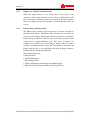
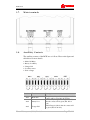
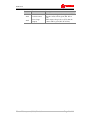
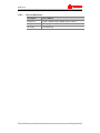
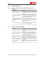
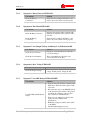
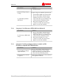
BCPS 2440
Battery Charger-cum-Pow er Supply
State-of-the-art equipment with Switching Mode technology for round-the-clock
applications
Installation and User Manual
BCPS 2440
Contents
Chapter 1: Safety Instructions....................................................................................3
1.1.
1.2.
1.3.
1.4.
1.5.
Important Safety Instructions ....................................................................................... 3
Receiving and Unpacking ............................................................................................ 3
Returns ......................................................................................................................... 3
General Information ..................................................................................................... 3
Warranty....................................................................................................................... 3
Chapter 2: Installation ................................................................................................3
2.1.
2.2.
2.3.
2.4.
2.5.
2.6.
Required Installation Tools and Materials ................................................................... 3
2.1.1.
Tools ........................................................................................................... 3
Inventory ...................................................................................................................... 3
Site Preparation ............................................................................................................ 3
2.3.1.
Input Power Specifications ......................................................................... 3
2.3.2.
Dimensions ................................................................................................. 3
Installation Requirements............................................................................................. 3
Installation .................................................................................................................... 3
2.5.1.
Inspection.................................................................................................... 3
2.5.2.
Installation................................................................................................... 3
2.5.3.
System Test................................................................................................. 3
2.5.4.
Commissioning ........................................................................................... 3
2.5.5.
Site Cleaning............................................................................................... 3
Wall Mount Figures with Dimensions ......................................................................... 3
2.6.1.
Figure Depicting the Placement of BCPS on the wall ................................ 3
2.6.2.
Figure Depicting the fixing of BCPS to the wall ........................................ 3
2.6.3.
Fixing Procedure......................................................................................... 3
2.6.4.
View of the BCPS after Complete Installation ........................................... 3
Chapter 3: System Description ...................................................................................3
3.1.
3.2.
3.3.
3.4.
3.5.
3.6.
3.7.
3.8.
3.9.
3.10.
General System Description ......................................................................................... 3
Parts Description .......................................................................................................... 3
Physical Dimensions .................................................................................................... 3
Functional Modules...................................................................................................... 3
Description of Functional Modules.............................................................................. 3
3.5.1.
Input over Voltage Protection Circuit ......................................................... 3
3.5.2.
Line Filter.................................................................................................... 3
3.5.3.
Inrush Current limiting circuit, Input Rectifier and Filter........................... 3
3.5.4.
Switching Mode Regulator ......................................................................... 3
3.5.5.
Output over Voltage Protection Circuit ...................................................... 3
3.5.6.
Battery charger with protection................................................................... 3
LED Indicators, Alarms, Meters & Switches............................................................... 3
3.6.1.
LED Indicators............................................................................................ 3
3.6.2.
Alarms......................................................................................................... 3
3.6.3.
Meters ......................................................................................................... 3
3.6.4.
Switches ...................................................................................................... 3
Main terminals.............................................................................................................. 3
Auxiliary Contacts........................................................................................................ 3
Technical Specifications............................................................................................... 3
3.9.1.
Mains Side .................................................................................................. 3
3.9.2.
Battery Side................................................................................................. 3
Other Specifications................................................................................................. 3
Kernex Microsystems (India) Limited
Page 2 of 41
BCPS 2440
3.10.1.
3.10.2.
3.10.3.
3.10.4.
3.10.5.
General........................................................................................................ 3
Performance ................................................................................................ 3
Protection and Safety .................................................................................. 3
Environmental............................................................................................. 3
Physical Dimensions................................................................................... 3
Chapter 4: Operation ..................................................................................................3
4.1.
Instructions to operate BCPS ....................................................................................... 3
Chapter 5: Maintenance & Troubleshooting ............................................................3
5.1.
5.2.
Maintenance ................................................................................................................. 3
Trouble Shooting.......................................................................................................... 3
5.2.1.
Symptom 1: NO Output Power and NO Mains, Charger ON LED
Indications .................................................................................................................... 3
5.2.2.
Symptom 2: Mains OFF LED lit ON.......................................................... 3
5.2.3.
Symptom 3: Battery Reverse LED lit ON................................................... 3
5.2.4.
Symptom 4: Fuse Blown LED lit ON......................................................... 3
5.2.5.
Symptom 5: Low Output Voltage and Battery Low Indication lit ON....... 3
5.2.6.
Symptom 6: Over Voltage LED lit ON ...................................................... 3
5.2.7.
Symptom 7: Load ON Battery LED lit ON/OFF ........................................ 3
5.2.8.
Symptom 8: Load Disconnect LED lit ON when Mains fail ...................... 3
5.2.9.
Symptom 9: No Charger Output at battery terminals and NO Float/Boost
or Equalize ON LED Indications ................................................................................. 3
Chapter 6: Circuit Diagrams ......................................................................................3
6.1.
6.2.
Main Circuit Diagram of the BCPS.............................................................................. 3
Circuit Diagram of the Controller ................................................................................ 3
Kernex Microsystems (India) Limited
Page 3 of 41
BCPS 2440
Chapter
1: Safety Instructions
This Section Contains…
1.
Important Safety Instructions
Receiving and Unpacking
Returns
General Information
Limited Warranty
S AF E TY I N S T R U C TI O N S
Kernex Microsystems (India) Limited
Page 4 of 41
BCPS 2440
1.1.
I mp o r t a nt S a f e t y I n s t r uc t i o ns
This manual contains important instructions that should be followed
during installation and operation of the BCPS 2440 Battery- Charger cumPower supply.
The following symbols used in this manual stand for the purpose detailed
against each:
This symbol warns you of the presence of dangerous voltages and the risk of
electrical shock.
This symbol provides important information to take notice of.
It is advised that the BCPS 2440 Battery- Charger cum-Power supply
should only be installed by an authorized electrician in accordance with
local electrical codes and instructions contained in this manual.
Read this manual thoroughly before using the product and ensure to read
through this safety information completely. Keep this manual safely for
future reference.
Always follow the instructions contained in this manual, while operating the
product.
Before cleaning the product please unplug the power.
Carry the product to the installation site with care. Components inside the
unit may get damaged on dropping the product, resulting in short-circuit or
severe consequences when connected.
Power: Please follow the labeled specifications provided on the unit
before connecting the power source. Contact the manufacturer in case of
any doubt.
Power Cable: The power cables must be properly secured, as improper
connections may cause short-circuits, fire hazards or similar dangerous
consequences.
Foreign Objects or fluids: Do not allow any foreign objects or fluids into
the unit, to avoid any fatal consequences.
Kernex Microsystems (India) Limited
Page 5 of 41
BCPS 2440
Maintenance
Only qualified maintenance personnel are authorized to service the unit.
Switch OFF the equipment immediately and call the maintenance
personnel for assistance in case of the following:
• Damaged Power Cables or Power Sockets;
• Insertion of foreign objects or fluids;
• Inoperability of the unit, in spite of correct operations;
• Dropped or damaged unit;
• Any other hazards.
Replacements: Unauthorized replacement of the internal components is
restricted to avoid electric shock, short-circuits and similar hazards.
Contact the maintenance personnel or the Manufacturer before attempting
any replacements.
1.2.
R e c e i v i n g a n d Un p a c ki n g
Please unpack the contents carefully and compare the packing list. Any
discrepancy in this regard must be immediately brought to the notice of
M/S Kernex Microsystems (India) Limited (KMIL). Please check and
inspect for any damage of the equipment during the shipment and in case
of any damage, file immediately a complaint with the carrier consignee for
the damage.
Kernex Microsystems (India) Limited
Page 6 of 41
BCPS 2440
1.3.
R e t ur n s
If equipment is to be returned to the factory for any reason, please call M/S
Kernex Microsystems (India) limited between 9.00 a.m. and 5.45 p.m.
Indian Standard Time (IST) to request a Return Authorization Number
(RA.No) and include this number with the returning equipment along with
a description of the problem and the name, address and the contact number
of the sender. Carefully pack the equipment to prevent damage during
shipment. In case of need contact M/S Kernex Microsystems (India)
limited for packaging instructions.
Remember to write the RA.No on the outer case of the package prominently.
1.4.
G e n e r a l I n f o r ma t i o n
Changes or modifications to this product by other than an authorized service
facility could make the product warranty void.
• This booklet includes the latest information available at the time of
printing. M/S Kernex Microsystems (India) Limited (KMIL) reserves
the right to make changes to this product without further notices.
• If you have questions about the use of this product, contact your
KMIl’s Sales and Service Representative or at the address given in
section 1.5 below.
Kernex Microsystems (India) Limited
Page 7 of 41
BCPS 2440
1.5.
W a r r a nt y
KERNEX MICROSYSTEMS (INDIA) LIMITED
Plot No 7 “THRUSHNA”, Software Units Layout, Infocity, Madhapur,
HYDERABAD INDIA 500 081
Phone: 91 40 23113193
Fax: 91 40 23113191
Email: [email protected]
Kernex Microsystems (India) Limited (KMIL) warrants that the product
mentioned below will be free from defects in materials and workmanship for a
period of 24 months from the date of commissioning or 28 months from the date
of supply, whichever ends earlier. If any such product proves defective during
this warranty period, KMIL, at its option, either will repair the defective product
without charge for parts and labour, or will provide a replacement in exchange for
the defective product. Batteries used inside and breakage of glass or any other
fragile items are excluded from this warranty. In case of replacement of a
defective product with another one, the warranty shall expire on date
corresponding to the original product.
The Customer shall be responsible for identification of the defective unit,
packing, to and fro transportation to the nominated central maintenance facility
and transit insurance.
This warranty shall not apply to any defect, failure or damage caused by improper
use or improper or inadequate maintenance and care. KMIL shall not be
obligated, to repair damages resulting from:
a) Attempts by personnel other than KMIL maintenance personnel, to install,
repair or service the product,
b) Improper use or connection to incompatible equipment, or input voltage
supply beyond specified range,
c) Natural calamites, fire hazards, accidents, vandalism, theft or burglary.
This warranty is given by KMIL with respect to the product mentioned below in
lieu of any other warranties, expressed or implied. KMIL’s responsibility to
repair or replace defective products is the sole and exclusive remedy provided to
the customer in case of any faults identified. KMIL will not be liable for any
indirect, special, incidental, or consequential damages irrespective of whether
KMIL has advance notice of the possibility of such damages.
* Proof of purchase of the product and the purchase date shall be provided before
any warranty service can be performed.
Kernex Microsystems (India) Limited
Page 8 of 41
BCPS 2440
Chapter
2: Installation
This Section Contains…
Required Installation Tools & Materials
Inventory
Site Preparation
Installation Requirements
Installation
Mounting figures with dimensions
2.
Kernex Microsystems (India) Limited
Page 9 of 41
BCPS 2440
2.1.
R e q u i r e d I n s t a l l a t i o n T o o l s a nd M a t e r i a l s
2.1.1.
Tools
• Common Hand Tools
o
o
o
o
Set Spanner M6
Screwdriver Set
Wire Stripper
Cutting Pliers, 6”
• Power Drill
• M6 Wall Drill Bits
• Multi-meter
Please do not replace any of the screws or other fasteners on the equipment,
which may result in loss of warranty. If replacement is needed, please contact
M/S Kernex Microsystems (India) Limited.
2.2.
Inventory
•
•
•
•
2.3.
BCPS 2440 Battery Charger-cum-Power Supply Manual
Warranty / Registration Card
BCPS 2440 Battery-cum-Power Supply Unit
Installation Kit containing:
1. 25 mm Steel Glands—3 Nos.
2. M6 X 75 mm Anchor Bolts with drums—4 sets
3. M6 Plane Washers—4
4. M6 Spring Washers—4
5. Fuse 10A—2
6. Fuse 25A—2
7. MCBs (2pole 10A) with mounting box – 1No
Site Preparation
Please follow the below instructions for site preparation before installing
the unit.
2.3.1.
Input Power Specifications
• Voltage
• Current
:
:
190 - 270V AC, 50 Hz, ±2Hz
10 Amp
Kernex Microsystems (India) Limited
Page 10 of 41
BCPS 2440
2.3.2.
Dimensions
• Height
• Width
• Weight of unit
2.4.
:
:
:
350 mm
123 mm
10 Kg (approx.)
I ns t a l l a t i o n Re q ui r e m e n t s
• Be sure to read all the installation requirements and instructions before
beginning the actual installation.
This equipment requires a dedicated branch circuit rated at 220 V (Single Phase)
with minimum circuit capacity of 10 Amps and over current protection of 15
Amps.
• Position the power junction box such that the conduit and input wiring
•
•
•
can be connected.
The unit must be mounted at least 4 - 5 Feet above the floor.
The unit must be mounted at a location that allows an unobstructed
clearance all around for ease of maintenance.
The unit must be mounted and an electric point (MCB) of suitable
rating shall be provided near to this unit.
Kernex Microsystems (India) Limited
Page 11 of 41
BCPS 2440
2.5.
I ns t a l l a t i o n
2.5.1.
Inspection
1.
Remove the charger from its shipping container.
Please read the manual carefully before installation.
2.
Please find the following on the Unit:
i. Find and locate two top mounting holes.
ii. Find and locate two bottom mounting holes
2.5.2.
Installation
3.
4.
5.
6.
7.
8.
9.
10.
11.
12.
13.
Place the Charger Template on the wall (approx. 4’ - 5’ above the
floor) and mark the four holes with a marker.
Drill the holes on wall to suit M6 Anchor bolt with power drill
machine. Please refer figure at section 2.6.2.
Insert the Anchor Bolts drums into the drilled slots.
Lift the charger on to the wall and align it exactly with the drilled
holes on the wall and insert the Anchor bolts.
Hold the charger in place and tighten the anchor bolts (diagonally
opposite bolts) to full extent possible and repeat the same for the
bolts on the opposite side.
Check and ensure that the Charger is firmly fixed in its position.
Connect the Earth point of the charger with suitable copper wire to
the MCB box.
Open the charger Front Door and connect the charger I/P supply to
I/P terminals, Phase to L, Neutral to N and ground to G.
Connect the Load to the Load terminals on the charger (marked as
Load Terminals +Ve and -Ve).
Connect the Battery Terminals to the Battery terminals of the charger
(marked as Battery Terminals +Ve and -Ve).
All the wires into the charger and from the charger to be routed
through the PVC conduit and through the Cable glands.
Turn Off the circuit breaker at the service or distribution panel supplying the
electricity to the MCB box and verify that high voltage is not present before
performing the following steps.
2.5.3.
System Test
1.
Turn ON the MCB for the charger unit.
Kernex Microsystems (India) Limited
Page 12 of 41
BCPS 2440
2.
3.
4.
5.
2.5.4.
Switch on the unit by using ON/OFF switch located on the front
panel.
Observe the output voltage on the meter located on the front panel, it
should be 28.5V ±1V DC.
Observe the battery current on the meter located on the front panel
by selecting the battery/load current switch in battery current mode.
The reading depends on the battery condition.
By using Multi-meter, measure the battery voltage at battery
terminals and voltage depends on the battery condition.
Commissioning
1.
2.
3.
Connect the load.
Switch on the unit by using ON/OFF switch located on the front
panel.
After power ‘ON,’ the BCPS performs self diagnostics continuously.
During self diagnostics, the following functions/parameters are
checked by a microprocessor.
a.
Oscillator – working or not
b.
Output Voltage – within tolerance or not
c.
Battery Charge level
d.
e.
f.
g.
Mode of operation (Float / Boost)
AC Power status
Load on Battery
Overall Charger Functioning
On detection of any of the above failures the “Charger Failed” LED will be lit
ON. The microprocessor also monitors the charging and discharging current of
the battery. The battery charging level is continuously computed and the battery
low condition is decided based on charge – discharge cycles.
4.
Keep the Auto / Equalizer switch in Auto mode.
5.
6.
Observe the output voltage on the charger.
Measure the load current on the meter located on the front panel by
selecting the battery/load current switch in load current mode. The
reading depends on the load condition.
Change the mode switch to Equalize mode and measure the Output
voltage on the charger by varying the potentiometer located on the
front panel (26V to 30V DC).
Switch OFF the unit and connect the battery to the Battery terminals.
7.
8.
Kernex Microsystems (India) Limited
Page 13 of 41
BCPS 2440
9.
10.
11.
12.
13.
2.5.5.
Switch ON the unit and measure the charging current in the Ammeter
by selecting the selector switch to battery current mode. The
charging current depends on the battery condition.
Switch OFF the line input to the unit by switching OFF the MCB in
MCB box.
Observe the indication on the unit front panel “Mains Fail”.
Observe there is no power disturbance to load and also observe the
load current on the charger.
Observe the indication on the unit front panel “Load ON Battery”.
Site Cleaning
1.
Recover all packaging materials and clear all the debris at the site
area.
2.
Present this booklet to the owner.
Kernex Microsystems (India) Limited
Page 14 of 41
BCPS 2440
2.6.
W a l l M o u nt Fi g u r e s w i t h D i m e ns i o n s
2.6.1.
Figure Depicting the Placement of BCPS on the wall
Kernex Microsystems (India) Limited
Page 15 of 41
BCPS 2440
2.6.2.
Figure Depicting the fixing of BCPS to the wall
Kernex Microsystems (India) Limited
Page 16 of 41
BCPS 2440
2.6.3.
Fixing Procedure
Item
No
Part No
1
Wall
2
3
Anchor Bolt
Battery Charging Unit
4
Fasteners
5
6
7
Rounding Conduit
U-Clamp for Routing
IS 7483-M6-x40-Z-40 N
Description
Quantity
Wall with predrilled holes to suit M6 Anchor
Bolt
Standard M6x75 L Anchor Bolt
Battery Charger-cum-Power Supply Unit
M6 Flange Head Bolts with Spring & Plain
Washers
Suitable Conduit for Routing
Fixing of Routing Conduit
M6 Slotted Pan Head Screws
Kernex Microsystems (India) Limited
4
4
1
4
3
9
18
Page 17 of 41
BCPS 2440
2.6.4.
View of the BCPS after Complete Installation
Kernex Microsystems (India) Limited
Page 18 of 41
BCPS 2440
Chapter
3: System Description
This Section Contains…
General System Description
Parts Description, Physical Dimensions
Functional Modules & Description
Operating Principle with Block Diagram
LED Indicators & Alarms
Auxiliary Contacts
Technical Specifications
Protection & Safety
3.
Kernex Microsystems (India) Limited
Page 19 of 41
BCPS 2440
3.1.
G e n e r a l S y s t e m D e s c r i pt i o n
Kernex Microsystems (India) Limited’s BCPS 2440 Battery Charger-cumPower Supply (BCPS) unit is an Industrial Grade Equipment suitable for
highly demanding round-the-clock applications. BCPS 24/40 employs
state-of-the-art Switching Mode Technology to achieve high efficiency,
low power dissipation and small in size. High reliability of the unit is
achieved through vigorous quality checks, testing and environmental stress
screening during the manufacturing process. KMIL’s BCPS delivers load
to the equipment and simultaneously charges a battery in ‘Float Charge’
mode.
The BCPS operates on 190-270 V, 50Hz single phase AC supply and
delivers 28.5V output. The total current delivered by the BCPS will be
40A. The Block diagram of Battery charger cum power supply is shown at
figure given below.
System Block Diagram
Kernex Microsystems (India) Limited
Page 20 of 41
BCPS 2440
3.2.
P a r t s D e s c r i pt i o n
8
7
15
9
6
10
16
5
17
11
4
18
3
12
2
19
13
14
1
23
22
20
24
25
21
2
26
25
Legend
Label no
1
2
3
4
5
6
7
8
9
10
11
12
13
Description
Power ON/OFF switch
Buzzer ACK switch
Fuse blown
BATT Reverse
Equalizer Mode
Float
Boost
Charger OK
Load Disconnect
Load On Battery
Over Voltage
Battery Low
Mains Fail
Kernex Microsystems (India) Limited
Label no
14
15
16
17
18
19
20
21
22
23
24
25
Description
Mains ON
Voltmeter Selection Switch
Digital Voltmeter
Auto/ Equalize Selection Switch
Ammeter Selection
Ammeter
Door Lock
Heat Sink
Output Fuse
Input Fuse
Cable Glands
Unit Fixing Holes
Page 21 of 41
BCPS 2440
3.3.
P h y s i c a l Di m e n si o ns
Please note that all the measurements are in millimeters (mm)
Kernex Microsystems (India) Limited
Page 22 of 41
BCPS 2440
3.4.
F u nc t i o n a l M o du l e s
The Battery Charger-Cum Power Supply (BCPS) comprises of the
following modules:
Sl.No
1
Name of the Functional Module
Input Over Voltage Protection Circuit
2
Line filter
3
Inrush current limit, Input Rectifier and Filter
4
Switching mode regulator
5
Output over voltage protection circuit
6
Battery charger with protection
7
Indications, meters and manual controls
3.5.
D e s c r i p t i o n o f Fu nc t i o na l M o du l e s
3.5.1.
Input over Voltage Protection Circuit
When Input voltage (AC) exceeds 270V±2V, the input to the unit is
disconnected automatically; however, the output power to the load is
provided from the battery. When the input voltage falls below 245V±2V,
the normal operation is resumed automatically.
3.5.2.
Line Filter
The line filters EMI/RFI noise prevalent on the input lines to enter into the
charger output; similarly, it prevents the switching noise of the charger
unit entering into the AC power lines.
3.5.3.
Inrush Current limiting circuit, Input Rectifier and Filter
This section limits the power ON inrush current and also rectifies AC
voltage into DC voltage and filters the ripple. The output of this section
will be unregulated DC voltage.
3.5.4.
Switching Mode Regulator
The input DC voltage is converted into high frequency AC voltage by a
MOSFET switching element. This AC voltage is passed through a step
down isolation transformer with 1KV isolation and the output is rectified
and filtered. Pulse Width Modulation (PWM) technique is used for the
purpose of regulation.
The output feedback is obtained through isolation and given to the PWM
control circuitry.
Kernex Microsystems (India) Limited
Page 23 of 41
BCPS 2440
3.5.5.
Output over Voltage Protection Circuit
When the output reaches to over voltage, due to any reason, a rare
occurrence, Power supply unit trips on over voltage condition (above 30V
DC) and resumes to normal operation on removal of the fault condition.
The power supply folds back and resumes to normal operation at the AC
recycle.
3.5.6.
Battery charger with protection
The Battery Sense Circuitry senses the presence of battery and analyses
the health of the battery. The Battery Sense Circuitry also senses the load
connected to the battery during mains failure and provides an indication.
Battery charge condition is sensed by state-of-art sensing circuitry, which
works based on charge-discharge cycle. Two levels of battery low
conditions are realized, one for providing an alarm to the load control
circuitry for taking preventive action and second limit to disconnect the
battery from the load, to save the battery from deep discharge condition.
Both the battery low limits are adjustable.
The main advantages are:
• High efficiency
• Smaller Dimensions
• Short Charge Times
• Charge independent of the changes in the Mains Supply
• Electronic Control that provides the desired Charge Curve
Kernex Microsystems (India) Limited
Page 24 of 41
BCPS 2440
3.6.
L ED I n d i c at o r s , A l a r m s , Me t e r s & Sw i t c h e s
3.6.1.
LED Indicators
Indicator
3.6.2.
Description
Mains ON - Green
Will be lit ON when AC voltage is available
Mains Fail - Red
Will be lit ON along with buzzer when AC voltage is not
available
Battery Low - Red
Will be lit ON along with buzzer when the Battery
voltage is below 22.6±0.1V
Over Voltage - Red
Will be lit ON when the output voltage is above 30V DC
Load ON Battery Green
Will be lit ON when the load is on battery.
Load Disconnect –
Red
Will be lit ON when the Battery voltage is below
21.6±0.1V and load will be disconnect.
Charger ON - Green
Will be lit ON when Charger is in OK.
Boost - Green
Will be lit ON when charger is in Boost mode
Float - Amber
Will be lit ON when charger is in Float mode
Equalizer Mode - Red
Will be lit ON when charger is in Equalizer mode
Battery Reverse - Red
Will be lit ON when Battery is connected in reverse
polarity
Fuse Blown –Red
Will be lit ON when fuse is blown (i.e. the fuse
connected in series with the battery)
Alarms
Condition
Alarm Type
Action
Audible Alarm
Battery Low
When Battery voltage falls
down to under voltage
(22.5V)
Audible Alarm
Mains Failure
I/P AC supply is OFF
Acknowledgement Push
Button
Kernex Microsystems (India) Limited
To be pressed to reset the
audio alarm
Page 25 of 41
BCPS 2440
3.6.3.
Meters
Meters
3.6.4.
Type
Description
Voltmeter
Digital Meter
Display the BCPS Output / Battery
Voltage
Ammeter
Digital Meter
Display the LOAD current/ Battery
charge, discharge Currents.
Switches
Manual
Controls
Voltmeter
Selection
Ammeter
Selection
Auto/
Equalize
Selection
Switch
Type
Switch
Position
Description
1
To select the BCPS voltage
2
To select the Battery Voltage
1
Switch
2
1
This switch selects the Load current
To selects the Battery charge/
discharge current
To select the battery to Auto mode
Switch
Kernex Microsystems (India) Limited
2
To select the battery to Equalize mode
Page 26 of 41
BCPS 2440
3.7.
M a i n t e r mi n a l s
3.8.
Auxiliary Contacts
The auxiliary contacts of the BCPS are as follows. Please refer figure and
table below for more details.
•
•
•
•
•
Mains ON Relay
Battery Low Relay
Charger Fail
Load Disconnect
Over voltage
Section
Function
Aux1
Mains ON
Aux2
Battery Low
Aux3
Charger Fail
Kernex Microsystems (India) Limited
Description
Charger is working on Mains supply, then the
contacts will be given (NO, NC & Pole)
When battery voltage is discharged to 22.5V,
then the contacts will be given (NO, NC &
Pole)
When Charger is failed, then the contacts will
be given (NO, NC & Pole)
Page 27 of 41
BCPS 2440
Section
Function
Aux4
Load disconnect
Aux5
Over voltage
(Output)
Kernex Microsystems (India) Limited
Description
When battery voltage is discharged to 21.5V,
then the contacts will be given (NO, NC &
Pole)
When output voltage is above 55V, then the
contacts will be given (NO, NC & Pole)
Page 28 of 41
BCPS 2440
3.9.
T e c h ni c a l Sp e c i f i c a t i o n s
3.9.1.
Mains Side
Description
Supply Voltage
Symbol
3.9.2.
Unit
--
190 - 270
V AC
f
--
50 ±2
Hz
Iin Max
--
10
A
Battery Side
Description
Symbol
Test
condition
Value and / or
range
Unit
Maximum
Charging Current
I
--
20
A
Output Voltage
V
--
28.5
V
3 . 1 0.
O t he r Sp e c i f i c a t i o n s
3.10.1.
General
Description
Symbol
Efficiency
Maximum Power
Test
condition
Fc
Switching
Frequency
3.10.2.
Value and / or
range
Vin
Frequency
Maximum Current
Test
condition
Value and / or
range
--
85 ± 5
At 230V AC
and fully
loaded
>75%
P = P max
1200
Pin Max
Unit
KHz
W
Performance
Description
Test condition
Power Input
Nominal 230 V AC (range 190V to 270V single phase AC)
Line Frequency
50Hz – 60Hz ±2Hz
Output
28.5V at 40Amps max.
Battery charging current 20 Amps Max.
Regulation
Within ±2% when operating from Inverter; will follow the
Battery Voltage when operating from battery.
Ripple & Noise
Ripple on output load terminal < 100mV,
Noise < 300mV Pk-Pk
Kernex Microsystems (India) Limited
Page 29 of 41
BCPS 2440
3.10.3.
3.10.4.
Protection and Safety
Description
Test condition
Output over
Voltage
Power supply unit trips on over voltage condition (above
30V DC) and resumes to normal operation on removal of
fault condition
Output over
load/Short Circuit
Fold back current limit. It resumes to normal operation on
removal of the short
Battery Reverse
Polarity
Protected on reverse polarity connection (fuse blown), the
LED indication is provided
Battery Deep
Discharge
Limit 1:
When the battery voltage falls to 22.50 V, Indication with
audio alarm and Potential free contact as advance warning
Limit 2:
When the battery voltage falls below 21.5±0.2V load
disconnect indication and potential free contact.
The battery will cut-off from the load and only charging
takes place. When the battery voltage reaches 22.50±0.2V,
the battery will get connected to equipment output.
Fuse Protection
Provided for the mains supply and the Battery Reverse
Environmental
Description
Test condition
Operating
Temperature
Range from -10ºC to +60ºC
Humidity
95% RH
Kernex Microsystems (India) Limited
Page 30 of 41
BCPS 2440
3.10.5.
Physical Dimensions
Description
Test condition
Dimensions
Width: 350mm; Height: 300mm; Depth: 120 mm
Weight
10 Kgs approx.
Mounting
Wall Mounting
4.
Kernex Microsystems (India) Limited
Page 31 of 41
BCPS 2440
Chapter
4: Operation
This Section Contains…
Kernex Microsystems (India) Limited
Operating Procedures
Normal Operation Indications
Fault Condition Indications
Page 32 of 41
BCPS 2440
4.1.
I ns t r u c t i o ns t o o p e r a t e B C PS
• Switch ON the Power to the unit.
o
The Mains ON LED indication will be glowing Green to indicate the
availability of I/P supply.
o
The Charger ON LED indication will be glowing Green to indicate the
proper working status of the unit.
• The charger can be operated in ‘Auto’ mode or Equalizer’ mode. Periodically,
equalizer mode can be selected manually for dissolving any solidified sulphate
deposits on the battery plates. In this mode, charging voltage can be adjusted
manually (maximum Voltage of 30 V). After 1 hour, the charger can be put
back in ‘Auto’ mode.
o
If Auto mode is selected the Boost (Green LED) or Float (Amber LED)
will be glowing depending on the battery charging condition.
o
If Equalizer mode is selected the LED indication will be glowing Red.
• To decrease the charging time, change the Auto/Equalizer mode switch
to equalizer mode.
• For Normal charging, keep the mode selector switch in Auto mode.
Kernex Microsystems (India) Limited
Page 33 of 41
BCPS 2440
Chapter
5: Maintenance &
Troubleshooting
This Section Contains…
Maintenance Procedures
Troubleshooting Procedures
5.
Kernex Microsystems (India) Limited
Page 34 of 41
BCPS 2440
5.1.
Maintenance
Turn OFF your Charger unit at the circuit breaker before cleaning. To reduce the
risk of electrical shock or equipment damage, do not allow any liquid to enter the
unit while cleaning it.
Clean the charger unit with a clean, soft and dry cloth.
Do not use any abrasive pad, Scouring powder or flammable or non-flammable
solvents such as alcohol or benzene.
Take care not to break the Seal covering the Panel Lock. Refer to No.14 of figure
given at section 4.2.Do not break the seal on the front panel lock to open the
BCPS panel door during the warranty period. Warranty is liable for termination
in such a case.
Do not try to replace any parts of the BCPS during troubleshooting. Contact the
BCPS service representative in case of any unresolved problem immediately.
Kernex Microsystems (India) Limited
Page 35 of 41
BCPS 2440
5.2.
T r o ub l e S h o o t i n g
5.2.1.
Symptom 1: NO Output Power and NO Mains, Charger ON LED
Indications
5.2.2.
Check Point
Solution
Check the input fuse F1
Open the fuse and check the continuity with
multi-meter. If the fuse fails, replace it with a
new fuse.
Check AC input ON/OFF
switch
Disconnect the wires to the ON/OFF switch
on the Unit. Keep the switch to ON position
and check the continuity of the pole and way
connections with multi-meter.
Check the AC Input Voltage
and Check the Over Voltage
Protection
Circuit
If it is above 270V AC, there is no output.
Input voltage is below 270V AC then only the
charger will be ON.
Charger OK LED lit OFF
One of the functions tested by diagnostics has
failed if AC mains ON is OK.
Symptom 2: Mains OFF LED lit ON
Check Point
Solution
Check the input fuse F1
Open the fuse and check the continuity with
multi-meter. If the fuse fails, replace it with a
new fuse.
Check AC input ON/OFF
switch
Disconnect the wires to the ON/OFF switch
on the Unit. Keep the switch to ON position
and check the continuity of the pole and way
connections with multi-meter.
Check wiring from MCB to
Unit
If wires are cut, damaged or shorted, then
replace the wires with the same specifications.
Check MCB in MCB box
If MCB is in tripped condition, then switch on
the MCB
Check the Mains
Check the Main Supply at power distribution
panel.
Kernex Microsystems (India) Limited
Page 36 of 41
BCPS 2440
5.2.3.
5.2.4.
5.2.5.
5.2.6.
5.2.7.
Symptom 3: Battery Reverse LED lit ON
Check Point
Solution
Check the Battery
Connections
Check the wire coming from Battery to the
unit for any reverse, then connect properly.
Symptom 4: Fuse Blown LED lit ON
Check Point
Solution
Check the Battery side fuse
Open the fuse and check the continuity with
multi-meter. If the fuse fails, replace it with a
new fuse.
Check the Battery
Connections
Check the wire coming from Battery to the
unit for any reverse, then connect properly.
Symptom 5: Low Output Voltage and Battery Low Indication lit ON
Check Point
Solution
Check the Load Current
Charger is overloaded therefore reduce the
load on the charger.
Check the Load terminals
The Load terminals are shorted for any
reason, then remove the short
Symptom 6: Over Voltage LED lit ON
Check Point
Solution
Check the Output Voltage
Disconnect the Load and Check the output
voltage. If fault persists, change the unit.
Symptom 7: Load ON Battery LED lit ON/OFF
Check Point
Solution
•
•
Load ON Battery LED lit ON
always
•
•
•
Kernex Microsystems (India) Limited
Open the fuse and check the continuity with
multi-meter. If the fuse fails, replace it with
a new fuse.
Disconnect the wires to the ON/OFF switch
on the Unit. Keep the switch to ON position
and check the continuity of the pole and
way connections with multi-meter.
If wires are cut, damaged or shorted, then
replace the wires with the same
specifications.
If MCB is in tripped condition, then switch
on the MCB
Check the Main Supply at power
Page 37 of 41
BCPS 2440
Check Point
Check the Charger Output
Voltage
Solution
distribution panel.
If output voltage not available, replace the unit.
•
•
Load ON Battery LED lit
OFF always
•
5.2.8.
Symptom 8: Load Disconnect LED lit ON when Mains fail
Check Point
Solution
•
Load disconnect LED lit ON
always
•
5.2.9.
Switch OFF the MCB and check the LED.
In case of fuse failure, check the battery
terminal connection for reverse polarity,
replace with same type and rating fuse and
connect the battery terminals properly.
If the battery terminals are loosely
connected or totally disconnected, then
tighten / reconnect the terminals.
In case of fuse failure, check the battery
terminal connection for reverse polarity,
replace with same type and rating fuse and
connect the battery terminals properly.
If the battery terminals are loosely
connected or totally disconnected, then
tighten / reconnect the terminals.
Symptom 9: No Charger Output at battery terminals and NO
Float/Boost or Equalize ON LED Indications
Check Point
Solution
Check the Battery Charger
output fuse (25A)
In case of fuse failure, check the battery
terminal connection for reverse polarity,
replace with same type and rating fuse and
connect the battery terminals properly.
Check the battery terminals
for tightness
If the battery terminals are loosely connected
then tighten the terminals.
Kernex Microsystems (India) Limited
Page 38 of 41
BCPS 2440
Chapter
6: Circuit Diagrams
This Section Contains…
Main Circuit Diagram
Circuit Diagram of Controller
6.
Kernex Microsystems (India) Limited
Page 39 of 41
BCPS 2440
6.1.
Ma i n Ci r c u i t Di a g r a m o f t h e B CP S
Kernex Microsystems (India) Limited
Page 40 of 41
BCPS 2440
6.2.
C i r c u i t Di a g r a m o f t h e Co n t r o l l e r
Kernex Microsystems (India) Limited
Page 41 of 41