1
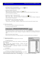
Machine Data Analyzer
MDA−3004
User’s manual
Introduction
Thank you very much for your purchasing of our product『e-p@k MDA-3004』.
e-p@k is the tool provided by our company to help operation rate improving activity of
customer’s equipment.
Machine data analyzer is the system to obtain number of items and times of items
(no work, full work, equipment error, and jig replacing, etc.) can be index of operation rate
from collecting data of all equipment and to generate graph display and text.
Please carefully read this manual before using and use our e-p@k correctly to improve
your company’s profit by making use of function of『e-p@k MDA-3004』
2
Contents
The first chapter Notices ...............................................................................................................................4
1.Notice for usage related to safety................................................................................................................................ 4
1-1.Danger ......................................................................................................................................................................................... 4
1-2.Caution........................................................................................................................................................................................ 5
1-3.Prevention from failure ......................................................................................................................................................... 5
2.Guarantee........................................................................................................................................................................................ 5
2-1.Guarantee condition............................................................................................................................................................... 5
2-2.Guarantee period..................................................................................................................................................................... 5
The second chapter Outline of system ..........................................................................................................6
1.What is e-p@k............................................................................................................................................................................... 6
1-1.e-p@k outline............................................................................................................................................................................ 6
1-2.e-p@k compatible type .......................................................................................................................................................11
2. e-p@k MDA outline....................................................................................................................................................................12
2-1. Flow of e-p@k MDA processing.....................................................................................................................................12
2-2. Function of e-p@k MDA processing ............................................................................................................................13
2-3. Analysis method of e-p@k MDA....................................................................................................................................16
The third chapter Installation of MDA-3004 .............................................................................................18
1. Installation of MDA ....................................................................................................................................................................18
2. Un-installation of MDA...........................................................................................................................................................20
The fourth chapter Operation method of MDA-3004.................................................................................21
1. Start of MDA...................................................................................................................................................................................21
2. Signal analysis................................................................................................................................................................................22
2-1. Setting of analysis macro file .........................................................................................................................................22
2-2. Detail setting of analysis macro file.............................................................................................................................27
2-3. Collecting data file selection...........................................................................................................................................34
2-4. Setting of analysis time range........................................................................................................................................36
2-5. Refresh function ..................................................................................................................................................................36
2-6. Analysis execution ..............................................................................................................................................................36
3. Signal analysis graph................................................................................................................................................................37
3-1. Display of graph....................................................................................................................................................................37
Appendix1 e-p@k various file explannation ...............................................................................................44
Appendix2 Trace file.....................................................................................................................................45
3
Notices
The first chapter
1.Notice for usage related to safety
In this manual important contents are listed to use safely and correctly by preventing safety hazard and damage of
property for user and adjacent person from occurring. Please read this manual carefully before using this machine
and comply with listed matters.Also never execute improper operations not listed in this manual otherwise it could
be cause of damage of MDA-3004 and injury for person.Remember that failure・trouble of personal computer and
erasing・damage of data or failure・trouble of this product caused by improper handling shall be out of guarantee of
our company.
1-1.Danger
This indication mark suggests the handling ignoring the mark may lead to
death or serious injury.
(1).Warning matters on design
・ This product is not supposed to use operation control device of equipment・device other than
「e-p@k system」. Failsafe system design for failure and stoppage of this product shall be executed
when this product is used for these usages. Also in this case install stop switch・emergency stop
switch separately giving priority to this product.
・ Never apply this machine to the usage related to safety of device・human body.
・ This product is not supposed to be applied such usages as aircraft instruments, aerospace instrument,
main line communication device, nuclear energy control equipment and medical instrument related to
life support where extremely high reliability and safety are required. Therefore this product cannot be
used for these usages.
(2).Warning items for wiring work
・ Execute installing confirming electric power is not supplied when interface connector is connected
because there is potential hazard that electric shock could be occurred.
・ Do not touch the equipment, etc. with wet hands. It could be cause of electric shock if power source
plug is connected to plug outlet.
4
The first chapter
Notices
1-2.Caution
This indication mark suggests the handling ignoring the mark may lead
to injury or physical damage.
(1).Notices during mounting
・Attach cable to connector surely. Otherwise it could be cause of incorrect input or incorrect output.
(2).Warning items for wiring work
・Wiring to main body shall be executed correctly after confirming rated voltage. It could be cause of fire and
failure when power source is connected to other than rated voltage and incorrect wiring should be executed.
・Connection with main body of PLC shall be executed by following the warning・notice of instruction of PLC
manufacturer and peripheral equipment manufacturer.
(3).Others
・All data inside personal computer (hard disk, etc.) shall be saved in MO and FD, etc. as backup when
software is installed or before change when any of computer environment is tried to change. Suffering can be
controlled at the minimum when data was erased or damaged by occurrence of failure and handling error.
Remember that we have no liability for erasing or damage of data due to neglecting of data backup saving.
1-3.Prevention from failure
・Avoid storing and using of this product under the direct sun shining.
・Handling of personal computer, PLC, and peripheral equipment shall be executed according to procedure
specified by manufacturer of these devices after carefully reading respective manual.
2.Guarantee
2-1.Guarantee condition
Carefully read description of 『Service condition of this program』 indicated in this manual.
2-2.Guarantee period
(1).Guarantee period
Guarantee period shall be 12 months after shipping from our factory. (For three (3) months when failure is
the same repaired portion.) We will repair free of charge (factory repairing) when cause of failure is due to
our company’s responsibility under normal environmental condition specified in general specifications.
(2).Guarantee range
Such software other than preinstalled 「e-p@k system」 as system, application software, and drivers that
are installed by customer shall be controlled by customer.
5
Outline of system
The second chapter
1.What is e-p@k
1-1.e-p@k outline
e-p@k is general term of production support system to monitor integrated overall production process and to
execute investigation of cause to interfere equipment operation.
You can utilize this product as a tool to find problem process out of overall production processes, to grasp
abnormal state and idle time remained within equipment by specific focusing of problem phenomena in the
problem process, and to help operation rate improvement activities in production process by investigating
cause of failure that has no recurrence.
In plant LAN
Visualizing tool
Storing control
function
e-p@k
Andon
Collecting
function
Bridge
1. Problem process can be observable.
2. Problem phenomenon can be identified.
3. Equipment idle time can be grasped.
CF card
Remained problems
・Variation among processes
・Loss time induced equipment error
disposition and taking action
・Loss time induced jig replacing set-up, etc.
・Bug present in PLC programming
・Operation failure of actuator and sensor
・Incorrect timing
4. Not producible failure
cause can be grasped!
5. Abnormal state in overall
processes can be grasped!
6. Equipment stop time
can be reduced
by predictive maintenance!
6
Analysis function
(Personal terminal)
The second chapter
Outline of system
(1).Basic workflow
PLAN
PLAN
DO
CHECK
①.
②.Drawing
③.PLC information
④.Drawing・analysis
Setting is made how
to draw and analysis
collected PLC information and under
what condition.
Actually connect to
PLC and collect information from operating
equipment.
Collected PLC information is made drawn,
analyzed, and displayed
to investigate the cause.
Collecting
condition setting
Setting is made what
condition and where shall
be collected by addressing
to destination of
PLC information.
condition setting
collecting
ACTION
Operation rate improvement activity
⑤.
Analyzed result
Improvement activities are executed for the causes that are
preventing improvement of operation rate.
Operation rate of production process is made improved by circulating “PDCA cycle” mentioned above.
(2).Structure and commercial goods of e-p@k
Following commercial goods can be selected so that effective operation rate improvement activity can be
made matching with production process of customer.
Product name
Machine data recorder
(Collecting box-PC)
Collecting
software package
Drawing
software package
Analyzing
software package
Product model
MDR−3004
Explanation
Permanent installation model BOX-PC to
collect information on equipment
MDR(S)−3004 Software package to collect information on
equipment
MDV−3004
Software package to draw or analyze
information on collected equipment
MDA−3004
Software package to analyze information on
collected equipment
7
The second chapter
Outline of system
Structure①.In case collecting using notebook computer,
etc.
From collecting to drawing・analyzing is executed using
one set notebook computer by installing 「Collecting
software package MDR 」 and 「 Drawing ・ analyzing
software package MDV」into the computer.
Structure②.In case equipment information collecting
dedicated BOX-PC (MDR) is used
Install 「 Drawing ・ analyzing software package MDV 」
into personal computer. And collecting is made using
collecting software package installed 「 BOX-PC for
collecting」 and drawing・analyzing is executed using
MDV personal computer. (MDR is sold separately.)
Structure③.In case collecting information using network
environment (wired)
Installation is the same with structure ②.
LAN setting of equipment information collecting
dedicated BOX-PC (permanent installation type) is
executed and drawing ・ analyzing is executed by
transferring collected equipment information to MDV
installed another personal computer by way of LAN.
(Optional device is required when network is used.)
Dedicated
cable
Equipment
PLC
CF card
Equipment
PLC
8
Collecting dedicated
BOX-PC(Permanent
installation type)
Computer used for
drawing・analyzing
Dedicated
cable
In-plant LAN
HAB
Equipment
PLC
Bridge
Collecting
dedicated BOX-PC
OA LAN
Dedicated
cable
Equipment
PLC
Structure④.In case collecting information through network
environment (wireless LAN)
Installation is the same with structure ②.
Wireless LAN setting of equipment information
collecting dedicated BOX-PC (permanent installation
type) is executed and drawing・analyzing is executed by
transferring collected equipment information to MDV
installed another personal computer by way of wireless
LAN. (Optional device is required when wireless LAN
is used.)
Notebook computer used for collecting
and drawing・analyzing
Computer used for
drawing・analyzing
Collecting
dedicated BOX-PC
Dedicated
cable
Bridge
Equipment
PLC
Collecting
dedicated BOX-PC
Access point
OA LAN
Dedicated
cable
Wireless LAN
Equipment
PLC
Collecting
dedicated BOX-PC
Computer used for
drawing・analyzing
The second chapter
Outline of system
(3).Feature of e-p@k
①. Connection to PLC is easy
Information shall be collected making targeted equipment actually operating by directly connecting PLC
(Programmable Logic Controller) that controls the equipment actually when information of production
process is collected.In this regard, only connection of dedicated cable to CPU card in PLC completes
wiring. Such equipment modifications as additional wiring for link card and addition of ladder software are
not required.
[Conventional]
Memory high-coder
[e−p@k]
35 [H]
1 [H]
Preparation 10H
Preparation 0.35H
Collecting
5H
Collecting
Editing
20H
Editing
0.50H
0.15H
Only following works just enough if e-p@k is installed:
・Only wire connection to periphery tool connection
I/F provided at CPU of PLC is just enough.
・Maximum 300 points (word) regardless device
・Data is displayed on personal computer.
Following works are required to observe data:
・Addition of output card to equipment PLC
・Wiring of memory high coder
・Document editing based on recorder paper
②. Information collecting availing network is possible.
Data collecting from office is possible without going off to production plant when e-p@k is used under
LAN environment.
③. Various analysis tools allowing the support for operation rate improvement activity
Drawing・analyzing tool can provide such abundant observable methods as 『Cycle chart』 and 『Gantt
chart』, real time drawing of these charts, CSV conversion, and chart conversion of Microsoft ® Excel.
④. Responding to various languages such as Japanese, English, and the third language
Duplicated purchasing for each language: Japanese version for domestic use and English version for
overseas is not required.Changing over from Japanese to English is provided
(4).Corresponding PLC maker and model name of e-p@k
Maker
Corresponding model name
MITSUBISHI Electric A series, Q series, Q-A series,
Co., Ltd.
FX series (only software packager version)
OMROM Co., Ltd.
CS series, CV series, CJ series,
C series, α series
CQM1 series, CPM series
Sharp Co., Ltd.
JW series
Allen-Bradley
SLC500 series
Maker name and product name are brand or registered brand of each company.
Model name of PLC that is currently not yet responding is under developing. Inquire to our company if
you need to know current developing state.
9
The second chapter
Outline of system
(5).Observable contents through e-p@k
①. Cycle chart
Controlled operation state can be displayed as cycle chart using production equipment PLC.Also
registering standard data and superposing it into current operation state allows you operation difference
at error state.
②. Gantt chart
Actual operation state of production process
can be displayed by collecting equipment
operation state.
Gantt chart also provides relation before and
after occurrence of some action in visual state.
(Gantt chart also can be outputted using
Microsoft ® Excel 2000.)
Under
setting-up
Error
occurrence
Normal
operation
③. Collecting data
Collected data can be converted into file format
(CSV file) of『Microsoft ® Excel』.
④. Analyzing data
You can find the key to improve operation rate from inclination of equipment by availing
『Machine data analyzer software』of e-p@k series. (Detail is referred to Machine data
analyzer software.)
10
The second chapter
Outline of system
1-2.e-p@k compatible type
(1).e-p@k MDR (S)-3004 compatible type
Computer main body DOS/V machine equipped processor of more than 300 MHz (more than 500 MHz recommended)
OS
Hard disk
Memory
Screen display
Application
Media
Windows2000 SP4、WindowsXP SP1a later
Free capacity of hard disk required to install is about 100 MB
More than 128 MB (more than 256MB recommended)
VGA more than 640 x 480 (SVGA more than 800 x 600 recommended)
Internet explorer Microsoft R IE 5.5 SPI later is required.
CD-ROM
Formal notation of Windows 2000 is Microsoft® and Windows® 2000 operating system.
Formal notation of Windows XP is Microsoft® and Windows®XP operating system.
(2).e-p@k MDV-3004 compatible type
Computer main body
DOS/V machine equipped processor of more than 500 MHz recommended
OS
Hard disk
Memory
Screen display
Application
Windows 2000 SP4, Windows XP SP 1a later
Free capacity of hard disk required to install is about 64 MB
More than 128 MB (more than 256MB recommended)
VGA more than 640 x 480 (SVGA more than 800 x 600 recommended)
Microsoft® Excel 2000 later is required for Excel output.
Internet explorer Microsoft R IE 5.5 SPI later is required.
CD-ROM
Media
Formal notation of Windows 2000 is Microsoft® and Windows® 2000 operating system.
Formal notation of Windows XP is Microsoft® and Windows®XP operating system.
(3).e-p@k MDA-3004 compatible type
Computer main body
DOS/V machine equipped processor of more than 500 MHz recommended
OS
Hard disk
Memory
Screen display
Application
Windows 2000 SP4, Windows XP SP 1a later
Free capacity of hard disk required to install is about 100 MB
More than 256 MB
VGA more than 640 x 480 (SVGA more than 800 x 600 recommended)
Media
ADO 2.10.4202 later is required.
CD-ROM
Formal notation of Windows 2000 is Microsoft® and Windows® 2000 operating system.
Formal notation of Windows XP is Microsoft® and Windows®XP operating system.
11
The second chapter
Outline of system
2. e-p@k MDA outline
2-1. Flow of e-p@k MDA processing
Various setting files are prepared from data collecting setting file (EPS), collected data file (EPD) is analyzed
referencing PLC. INI file, and the analyzed results are graph displayed.
Data
collecting
setting file
(EPS)
Analysis
macro
setting file
(AMC)
PLC file
(PLC.ini)
Collected
data file
(EPD)
File
preparation
Graph display
12
The second chapter
Outline of system
2-2. Function of e-p@k MDA processing
Analyzing possible function of e-p@k machine data analyzer (MDA) is explained.
(1). Signal analysis
Procedure to execute signal analysis is explained as following.
In case file existing
Analysis macro
file selection
In case file not existing
or changing
Collecting data
file selection
Analysis
execution
Analysis time
range setting
Graph display
Analysis macro
file setting
Time setting for out of
target
Analysis macro
file setting
In case previous analyzed
graph displayed
When time setting
for out of target is
specified
In case detail setting of
analysis function and
analysis coil executing
①. 1 signal ON time analysis
Records the time that analysis coil was turned
on and its duration of turning on and displays
the result in graph.
(Graph setting allows X-axis change from
[time] to [No.].)
Also [Distribution chart] can be changed
into [Bar graph] and also line can be drawn.
ON
OFF
Time
(sec)
100
80
Time 100
(sec)
80
60
40
60
20
40
20
YY/MM/DD YY/MM/DD YY/MM/DD
HH/MM/SS HH/MM/SSHH/MM/SS
1
2
3
No.
②. 1 signal ON-ON time analysis
Records the time that analysis coil was turned
on and the time elapsed time between the
previous turning on and subsequent turning
on then displays the result in graph.
(Graph setting allows X-axis change from
[time] to [No.].)
Also [Distribution chart] can be changed into
[Bar graph] and also line can be drawn.
ON
OFF
Time
(sec)
100
80
Time 100
(sec)
80
60
60
20
40
40
YY/MM/DD YY/MM/DD
HH/MM/SS HH/MM/SS
20
1
2
3
No.
13
YY/MM/DD
HH/MM/SS
The second chapter
Outline of system
③. 1 signal ON number of times
Records the number of times that analysis coil was turned on during specified unit of hour and displays
result in graph. Analysis macro setting specifies unit of time. Up to 86,400 (1 day) seconds can be
specified.
Graph setting allows X-axis change from
[time] to [No.].
ON
Also [Distribution chart] can be changed
OFF
Unit time Unit time unit time
Unit time Unit time Unit time
into
[Bar graph] and also line can be drawn.
Number of times
Number of times
(Time)
(time)
4
4
3
3
2
2
1
1
1
2
3
4
5
6
No.
YY/MM/DD YY/MM/DD YY/MM/DD YY/MM/DD YY/MM/DD YY/MM/DD YY/MM/DD
HH/MM/SS HH/MM/SS HH/MM/SS HH/MM/SS HH/MM/SS HH/MM/SS HH/MM/SS
④. 1 signal ON register analysis Records the time analysis coil was turned on and register value at
turned on and displays result in graph.
Graph setting allows X-axis change
ON
from [time] to [No.].
OFF
Register data10
(However analysis cannot be executed
when maker and model are selected.)
Also [Distribution chart] can be changed
into [Bar graph] and also line can be drawn.
20
15
25
YY/MM/DD
HH/MM/SS
YY/MM/DD
HH/MM/SS
YY/MM/DD
HH/MM/SS
Measured value (unit)
30
Measured value (unit)
20
30
20
10
10
YY/MM/DD
HH/MM/SS
1
2
3
4
No.
Register value is converted
by specified method in
analysis macro. Conversion
table is shown as shown in
right. Highest-order bit is
used as code when code is
present.
Register is prepared by
deleting・combining the data
according to specified size.
Size
(bit)
4,
8,
12, 16,
32
Conversion
type
HEX
BINARY
Code
Yes/No
Max. and min.
value
Max.and
value
min.
BCD
Example in case of register (4 bits)
M0000
M0000
M0000
8 th bit
7th bit
6th bit
M0000
5 th bit
Example in case of register (32 bits)
M0003
M0002
M0001
8 th bit
8th bit
8th bit
M0000
8 th bit
Example in case of address (8 bits)
X0007
X0006
X0005
1 th bit
1th bit
1th bit
X0004
1 th bit
14
Scale factor
Unit conversion by multiplying
constant value.
Unit conversion by multiplying
constant value.
M0000
4th bit
M0000
3 th bit
M0000
2 th bit
M0000
1th bit
X0003
1th bit
X0002
1 th bit
X0001
1 th bit
X0000
1th bit
The second chapter
Outline of system
Voltage data conversion from +10V∼ (with code) to pressure data from 1MPa ∼ -1MPa by
prepares binary data 16 bits is shown as following.
Register data is converted into analogue data and multiplies the data by 0.1.
Parameters in this case are as following:
32767
(7FFFh)
Size:
16 bits
Conversion type:
Binary
Code:
present
−10V
+10V
Maximum value:
+10
Minimum value:
-10
Scaling factor:
0.1
−32768
(8000h)
Unit:
MPa
⑤. 2 signals ON-ON time analysis
Records the time that analysis coil A was
turned on and the elapsed time between the
time that analysis coil A was turned on and
the time analysis coil B was turned on and
displays the result in graph.
Graph setting allows X-axis change from
[time] to [No.].
Also [Distribution chart] can be changed into
[Bar graph] and also line can be drawn.
ON
Analysis coil A
OFF
ON
Analysis coil B
OFF
Time
(sec)
30
20
Time
(sec)
30
10
20
YY/MM/DD
HH/MM/SS
10
1
2
3
4
YY/MM/DD
HH/MM/SS
YY/MM/DD YY/MM/DD
HH/MM/SS HH/MM/SS
No.
⑥. Multi signals ON analysis
Records analysis coil was turned on and
number of times and displays result in graph.
(Up to maximum 256 analysis coils can be
specified.)
They can be changed over into [Bar graph] of
[Item unit].
Y-axis can be selected [Number f times] and
[Time].
Analysis coil1
ON
OFF
Analysis coil 2
15
OFF
Analysis coil 3
15
20
ON
15
ON
OFF
20
15
Number of times
(times)
3
Number of times
(times)
3
Analysis coil 1
2
Analysis coil 2
2
Analysis coil 3
1
1
Analysis
coil 1
Analysis
coil 2
Analysis
coil 3
10
15
20
30
40
50
Times(sec)
The second chapter
Outline of system
2-3. Analysis method of e-p@k MDA
(1). What analysis coil means.
Analysis coil is explained taking following as example.
Transfer up
end
Transfer up
Coil No.
X0001
Y0001
D001
Coil comment
K=1.5 L=3.0
【A contact point】
Condition is satisfied
when signal is turned
on.
【B contact point】
Condition is satisfied
when signal is turned
off.
Transfer goes up time
【K】
【L】
When signal that turning on
time is less than specified value
it is not deemed turned on.
(Unit is second.)
Next, when required time to turn
on signal is less than specified
value it is deemed turned on.
(Unit is second.)
In this case, when X0001 is ON and Y0001 is OFF analysis coil D001 is recognized condition
is satisfied.
Analysis coil time chart
X0001
Y0001
ON
OFF
ON
OFF
X0001 AND ON
Y0001 OFF
Deemed continuously
turned on because turning
off time is less than L
D001
Deemed not turned on
because turning on time
is less than K.
ON
OFF
This duration of time is deemed turning on time of analysis coil D001.
16
The second chapter
Outline of system
(2). Self-holding time of analysis coil
Analysis coil time series is prepared by following calculation by stacking up previous calculation
result when analysis coil itself composes contact point.
Transfer up end
X0001
Transfer up
D001
Y0001
K=0
L=0
Transfer goes up time
Transfer
up time
D001
OR line
In this case, when X0001 is ON and Y0001 is OFF additionally previous D001 is ON and Y0001 is
OFF, analysis coil D001 is recognized condition is satisfied.
Anal ysis coil time chart
X0001
Y0001
D001
ON
OFF
ON
OFF
ON
OFF
[Caution]
Self-holding data that was stacked up shall not take over when extended time (time from
final data of previous time and top data of subsequent file) of collected data file is
exceeded 「File exceeding effective period」. (Refer to Appendix 2 Trace file).
Also self-holding data that the first data after elapse of out of target time shall not be
taken over when out of target time is set.
X0001 0001111111000000
Y0001 1111110000001111
D001 0000001111110000
Stack
0000001111110000
17
The third chapter
Installation of MDA-3004
1. Installation of MDA
Installation method of MDA-3004 is explained. (Note)
Set CD for installation of MDA-3004 to CD drive.
[Caution]
Ten (10) days limited time offer is available when installation is completed. Installation of
MDV-3004 is required for continued availing. Detail of installation of MDV-3004 is referred
to 「Installation Manual」.
Stop all programs before installation is made, otherwise installation could not be executed
normally.
①.Following diagram box is displayed automatically then click “Next” button.
When the dialogue is not displayed directory start “Setup.exe” file of install media.
②. 「Selection of installation destination」 dialogue is displayed.
Push “Reference” button to select holder when installation destination holder is changed.
Push “Next” button.
18
The third chapter
Installation of MDA−3004
③.「Set up status」 dialogue is displayed and copy of file is started.
At this point, following message is displayed when MDAC (Microsoft Data Access Components)
version 2.10.4202.1 or later is not installed.
Push “Yes” button then installer of MDAC is started. Install MDAC according to explanation.
Push “No” button then installer is not started. However, reading of MDB file will be failed when
MDAC is not installed.
[Caution]
MDAC (Ver 2.60.6526.3) of Japanese version is installed for Japanese OS.
Install MDAC (Ver 2.60.6526.3) of English version is installed for OS other than Japanese.
Install at user side when another version MDAC is required to install or MDAC of other
language is required to install.
④. Copy and register when 「MSCOMCTL. OCX」 file is not existed in system holder.
Following message is displayed when registration is completed successfully then click “OK” button
⑤. When installation is normally completed [Completion of InstallShield wizard] dialogue is displayed
then click “Completion” button.
19
The third chapter
Installation of MDA−3004
2. Un-installation of MDA
Un-installation method of MDA-3004 is explained.
①. Select [Setting] - [Control panel] from 「Start」 menu and start 「Addition and deletion of
application」.
②. Select “Machine Data Analyzer” from 「 Addition and deletion of application 」 and click
“Change/delete” button.
③. 「Setup status」 dialogue is displayed and deletion of file is started.
④. When un-installation is completed then 「Completion of maintenance」 dialogue is displayed then
click “Completion” button.
20
The fourth chapter Operation method of MDA-3004
1. Start of MDA
Start 「Program」-「Machine Data Analyzer」 from 「Start」 menu. 「Machine Data Analyzer」 dialogue
box is displayed.
Signal analysis: Signal analysis screen is displayed.
Signal analysis graph: Signal analysis graph display screen is displayed.
Language: Language changeover screen is displayed.
Select screen display required language and click “OK” button.
Close: Machine data analyzer is terminated.
[Caution]
Surely stop all programs at e-p@k starting, otherwise installation could not be executed normally.
21
The fourth chapter
Operation method of MDA-3004
2. Signal analysis
Click “Signal analysis” button from 「Machine Data Analyzer」 then 「Signal analysis」 dialogue is
displayed.
2-1. Setting of analysis macro file
(1). Selection of analysis macro file
Push “Selection” button of 「Analysis macro file selection」.
「Analysis macro file selection」 dialogue is displayed then select file and push “Open” button.
(2). Setting of analysis macro file
Push “Setting” button of 「Analysis macro file selection」.
「Analysis macro setting」 dialogue is displayed.
(Note) Value of selected file is initially
displayed when analysis macro
file is selected. Change of maker
and model cannot be executed.
22
The fourth chapter
Operation method of MDA-3004
①. Analysis macro file new preparation
Select [File] - [New preparation] from menu or push
All the values in dialogue box are cleared.
button.
②. Opening of analysis macro file
Either select [File] - [Open] from menu or push
button.
「Analysis macro file selection」 dialogue is displayed then select file and push “Open” button.
Value of selected file is displayed.
③. Overwrite saving of analysis macro file
Either select 「File」 - 「Overwrite saving」 from menu or push
button.
File is saved with the same name. However 「Analysis macro file saving」 dialogue is displayed
when file name is not specified.
④. Saving analysis macro file together with naming
Select 「File」 - 「Saving with naming」 from menu.
「Analysis macro file saving」 dialogue is displayed then select file and push “Saving” button.
(3). Collecting setting file
Select collecting condition setting file of collected data.
①. Collecting setting file selection
Push “Selection” button of 「Collection setting file」 from 「Analysis macro setting」 dialogue then
「Collecting setting file selection」 dialogue is displayed. (Extension of file displayed becomes
EPS.)
Select file and push “Open” button.
Bit selection of selected data collecting setting file or word selected all values are displayed.
(4). Collecting data address
Address operation of collecting data file is executed.
①. Comment filtering
Only specified character existing in the comment of collecting data
file is displayed.
Enter character into 「 Comment filtering 」 dialogue and push
“Execute” button or “Enter” key.
Difference between capital letter and small letter is not classified
but difference between double-byte character and one-byte
character is classified.
②. All display
All values that are bit selected or word selected are displayed.
③. Sorting in ascending order/descending order
Sorting is executed according to pushed tag when tag (address,
device classification, device code, comment) is pushed.
Sorting is changed ascending order ⇒ descending order ⇒ ascending order by each pushing.
23
The fourth chapter
Operation method of MDA-3004
(5). Addition of analysis function
Analysis executing function of collected data is added.
Notices at the time addition of analysis function are shown as following:
・Analysis function No. is “A001∼A999”.
・Analysis function No. is sorted in ascending order.
・Analysis coil No. is “D001∼D999”.
・Analysis coil No. is assigned vacant least No.
・Analysis function and comment of analysis coil makes comment of data collecting setting file initial
setting.
①. 1 signal ON time analysis
Select [Collecting data address] and push [1 ON] button.
Selected all lines are added when plural lines of [Collecting data address] are selected.
②. 1 signal ON-ON time analysis
Select [Collecting data address] and push [1 ON-ON] button.
Selected all lines are added when plural lines of [Collecting data address] are selected.
③. 1 signal ON number of times
Select [Collecting data address] and push [1 ON NUM.] button.
Selected all lines are added when plural lines of [Collecting data address] are selected.
[Unit time] that the value set at previous time becomes initial value.
④. 1 signal ON register analysis
Select [Collecting data address] and push [1 ON REG] button.
Selected all lines are added when plural lines of [Collecting data address] are selected.
[Register address] that the initial address of data collecting setting file becomes initial
value.
[Size, conversion type, code, maximum value, minimum value, unit, scaling factor] that
the value set at previous time becomes initial value.
⑤. 2 signals ON-ON time analysis
Select [Collecting data address] and push [2 ON-ON] button.
⑥. Multi signal ON analysis [MULTI ON] button
Select [Collecting data address] and push [MULTI ON] button.
[Collecting data address] can be selected maximum 256 addresses.
24
The fourth chapter
Operation method of MDA-3004
(6). Edit of analysis function
Edit of collected data analyzing function is executed.
①. Change of address
Select one line of [Collecting data address].
Select one line that address of [Analysis function setting] exists.
Push [>] button then changed into selected address.
②. Address addition of multi signal ON analysis
Select [Collecting data address]. (Plural lines can be selected.)
Select multi signal ON analysis of [Analysis function setting].
Push [>>] button then selected addresses are added.
③. Change of parameter and comment
Select change required line of [Analysis function
setting].
Data of selected line is displayed on [Parameter]
and [Comment] box then change parameter・
comment. Change is executed by pushing either
“Input” button or “ENTER” key.
After change selected line moves to one line
under.
Focus moves to parameter/comment box by
pushing “ENTER” key or double clicking of
change required line using mouse during change
required line of [Analysis function setting] is
selected.
④. Deletion of analysis function
Select deletion required line of [Analysis function
setting].
(Select headline in case of multi signal ON analysis.)
Click “Delete” button then selected function is deleted.
Right clicking of mouse also can execute the deletion.
Popup screen is displayed and selection of “Delete” deletes selected function.
⑤. Address deletion of multi-signal ON analysis
Select deletion required line of multi-signal ON analysis in [Analysis function setting].
Click “Delete” button then selected address is deleted.
Right clicking of mouse also can execute the deletion.
Popup screen is displayed and selection of “Delete” deletes selected address.
⑥. Address AB changeover of 2 signals ON-ON time analysis
Select line of 2 signals ON-ON time analysis of [Analysis function setting].
Push “Coil address A/B changeover” button then address A/B is changed over.
Right clicking of mouse also can execute the deletion.
Popup screen is displayed and selection of “Coil address A/B changeover” button changes
over address A/B.
25
The fourth chapter
Operation method of MDA-3004
(7). Analysis macro detail setting
Push [Analysis macro detail setting] button.
Detail setting of analysis macro can be executed. (Detail is referred to [2-2. Analysis macro file
saving].)
Analysis macro is changed and [Analysis macro file saving] dialogue is displayed when not saved in
file.
(8). Maker and model display
Data collecting setting file is restored and displayed.
(9). Termination of analysis macro setting
Push “Close” button. Analysis macro setting is terminated.
Following confirmation message is displayed when analysis macro is changed and not saved in file.
Push “Yes” button when saved in file and push “No” button when saving is not executed.
Push “Cancel” button when [Close] is required to release.
26
The fourth chapter
Operation method of MDA-3004
2-2. Detail setting of analysis macro file
「Analysis macro detail setting」 dialogue is displayed when “Analysis macro detail setting” button of
「Analysis macro setting」 dialogue is pushed.
(Note) Value of selected file is initially displayed when analysis macro file is selected.
Yellow box indicates cursor.
Cursor is moved by arrow key (→, ←, ↑, ↓).
Maximum contact point 11 lines x 11 columns can be set for one analysis coil.
Up to 999 points can be set in analysis coil.
Maximum line of ladder can be (999x11) + 999 lines.
(1). File
①. New preparation
Either select [File]-[New preparation] from menu or push
Screen becomes initial state.
button.
②. Open
Either select [File]-[Open] from menu or push
button.
Following [Analysis macro file selection] dialogue is displayed.
Select file and push “Open” button. Value of selected file is displayed.
③. Overwriting
Select [File]-[Overwriting] from menu. Or push
button.
Save the same name when analysis macro file name is selected.
27
The fourth chapter
Operation method of MDA-3004
④. Save with naming
Select [File]-[Save with naming] then [Analysis macro file saving] dialogue is displayed.
Select file and push [Save] button.
[Caution]
Ladder check is executed at following items. Move cursor to error line at error when error is occurred.
・Analysis function shall be existed.
・Analysis coil shall be existed.
・Line shall not be disconnected.
・Specified analysis coil at analysis function shall be existed.
⑤. Termination of application
Select [File]-[Termination of application] from menu. [Analysis macro detail setting] is
terminated.
Push “Cancel” button when [Termination of application] is required to release.
(2). Edit
①. Restore
Select [Edit]-[Restore] from menu then return to previous state. Up to maximum 100 steps can be
restored.
②Cut-off
Move cursor to the position where cutting-off is required and select [Edit]-[Cut-off] from menu.
Or push
button. Transfers the value at cursor position to copy buffer and replaces cursor
position with blank.
③. Copy
Move cursor to the position where copy is required and select [Edit]-[Copy] from menu. Or push
button. Value of cursor position is transferred to copy buffer.
④. Labeling
Move cursor to the position where labeling is required and select [Edit]-[Label] from menu. Or
push
button. Labels transferred value to copy buffer by [Cut-off] or [Copy] at cursor position.
Labeling cannot be executed when copied item (contact point, analysis coil, function) and labeling
position are different.
⑤. Insertion
Move cursor to the position where insertion is required and select [Edit]-[Insertion] from menu.
Or push [Insert] key. Right side contact point including cursor position is moved to right
one-by-one and make cursor position blank.
Insertion cannot be executed unless number 11th column is [blank] or [-].
⑥. Delete
Move cursor to the position where deletion is required and select [Edit]-[Delete] from menu. Or
push [Delete] key. Cursor position is replaced with blank.
28
The fourth chapter
Operation method of MDA-3004
⑦. 1 line insertion
Move cursor to the position where line insertion is required and select [Edit]-[1 line insertion]
from menu. Moves all the line that is under the cursor including cursor line downward by 1 line
making cursor line blank.
⑧. 1 line deletion
Move cursor to the position where one line deletion is required and select [Edit]-[1 line deletion]
from menu. Deletes cursor line and moves all the lines that are under the cursor upward by 1
line.
⑨. Comment display
Select [Edit]-[Comment display] from menu.
Check mark is turned on or turned off. Comment of contact point is displayed when check mark
is turned on and termination state is taken over to next start up.
⑩. Font setting
Select [Edit]-[Font setting] from menu. [Font] dialogue box is displayed.
Font is set and push “OK” button. Terminated state is taken over to next start up but color
setting is ignored.
⑪. Data collecting setting file selection
Select [Edit]-[Data collecting setting file] from menu then [Data collecting setting file] dialog is
displayed. (File extension is EPS.)
(Note) Maker and model cannot be changed.
29
The fourth chapter
Operation method of MDA-3004
(3) Contact point / analysis coil / function
①. “A” contact point
Move cursor to the position where “A” contact point addition required and push
The cursor position becomes “A” contact point
The position becomes blank when the cursor position is already “A” contact point.
button.
②. “B” contact point
Move cursor to the position where “B” contact point addition required and push
button.
The cursor position becomes “B” contact point
The position becomes blank when the cursor position is already “B” contact point.
③. OR line
Move cursor to the position where OR line is required to draw and push
OR line is drawn left upper of cursor position.
OR line is deleted when OR line is already drawn at cursor position.
button.
④. Horizontal bar
Move cursor to the position where horizontal bar is required to add and push
Cursor position becomes horizontal bar.
The position becomes blank when cursor position is already horizontal bar.
button.
⑤. Analysis coil
Move cursor to the line where analysis coil is required to add and push
button.
Analysis coil is added at right end of cursor line.
Blank is replaced with horizontal bar when blank is present at cursor line.
Analysis coil cannot be added when analysis coil is already present at cursor line.
⑥. Function
Move cursor to the line where function is required to add and push
Function is added at cursor line.
Function cannot be added when cursor line is completely blank.
30
button.
The fourth chapter
Operation method of MDA-3004
(4). Property
①. Contact point
Move cursor to the position of contact point and
either select [Edit]-[Property] from menu or push
“Enter” key. [Property] dialogue is displayed.
Select “A contact point”, ”B contact
point”, ”Horizontal bar” or “Blank” from [Symbol
selection].
Select “Address” or “Coil address” from [Address
information] and select address.
Check “OR (Vertical line)” when OR line is drawn.
Push “OK” button then contact point information
is changed.
(Note) Changeover of tag (contact point, analysis coil, function) cannot be executed.
②. Analysis coil
Move cursor to the position of analysis coil and
either select [Edit]-[Property] from menu or push
“Enter” key. [Property] dialogue is displayed.
Select [Address]. (D001∼D999)
Enter [Setting value: K]. (Enter numeral to three
places of decimals.)
Enter [Setting value: L]. (Enter numeral to three
places of decimals.)
Enter [Comment].
Check “OR (Vertical line)” when OR line is drawn.
Push “OK” button then analysis coil information is
changed.
(Note) Changeover of tag (contact point, analysis coil, function) cannot be executed.
③. Function (1 signal ON time analysis)
Move cursor to the position of function and either
select [Edit]-[Property] from menu or push “Enter”
key.
Select 「1 signal ON time analysis」 from [Function
selection].
Select [Analysis coil address].
Enter [Comment].
Push “OK” button then analysis coil information is
changed.
(Note) Changeover of tag (contact point, analysis coil, function) cannot be executed.
31
The fourth chapter
Operation method of MDA-3004
④. Function (1 signal ON-ON time analysis)
Move cursor to the position of function and either
select [Edit]-[Property] from menu or push “Enter”
key. [Property] dialogue is displayed.
Select 「1 signal ON-ON time analysis」 from
[Function selection].
Select [Analysis coil address].
Enter [Comment].
Push “OK” button then analysis coil information is
changed.
(Note) Changeover of tag (contact point, analysis coil, function) cannot be executed.
⑤. Function (1 signal ON number of times analysis)
Move cursor to the position of function and either
select [Edit]-[Property] from menu or push “Enter”
key. [Property] dialogue is displayed.
Select 「1 signal ON-ON number of times analysis」
from [Function selection].
Select [Analysis coil address].
Enter [Unit time].
Enter [Comment].
Push “OK” button then analysis coil information is
changed.
(Note) Changeover of tag (contact point, analysis coil, function) cannot be executed.
⑥. Function (1 signal ON register analysis)
Move cursor to the position of function and either
select [Edit]-[Property] from menu or push “Enter”
key. [Property] dialogue is displayed.
Select 「1 signal ON register analysis」 from
[Function selection].
Select [Analysis coil address].
Select [Register address].
Select [Size] from [4, 8, 12, 16, 32].
Select [Conversion model] from [HEX, BINARY,
BCD].
Select [Code] from 「Yes, No」.
Enter [Maximum value]. (Enter numeral to three places of decimals.)
Enter [Minimum value]. (Enter numeral to three places of decimals.)
Enter [Unit].
Enter [Scaling factor]. (Enter numeral to three places of decimals.)
Enter [Comment].
Push “OK” button then function information is changed.
(Note) Changeover of tag (contact point, analysis coil, function)
(Note) [Code, maximum value, minimum value, scaling factor]
become invalid when [HEX] is selected in [Conversion model].
[Code, maximum value, minimum value] become invalid when
[BCD] is selected in [Conversion model].
32
The fourth chapter
Operation method of MDA-3004
⑦. Function (2 signals ON-ON time analysis)
Move cursor to the position of function and either
select [Edit]-[Property] from menu or push “Enter”
key. [Property] dialogue is displayed.
Select 「2 signals ON-ON times analysis」 from
[Function selection].
Select [Analysis coil A] and [Analysis coil B].
Enter [Comment].
Push “OK” button then analysis coil information is
changed.
(Note) Changeover of tag (contact point, analysis coil, function) cannot be executed.
⑧. Function (Multiple signal ON time analysis)
Move cursor to the position of function and either
select [Edit]-[Property] from menu or push “Enter”
key. [Property] dialogue is displayed.
Select 「Multi-signal ON times analysis」 from
[Function selection].
Select [Analysis coil] from [Analysis coil register]
and push “Register” button when analysis coil is
registered.
Select [Analysis coil] from [Registered analysis coil]
and push “Delete” button when analysis coil is
deleted.
Enter [Comment].
Push “OK” button then function information is changed.
(Note) Changeover of tag (contact point, analysis coil, function) cannot be executed.
(5). Help
①. Version information
Either select [Help]-[Version information…] from
menu or push
button. [Version information …]
dialogue box is displayed.
33
The fourth chapter
Operation method of MDA-3004
2-3. Collecting data file selection
Select either [Holder selection] or [File selection] from [Collection data file selection] of [Signal analysis]
dialogue box.
(1). Holder selection
Push “Select” button at [Holder selection] side when [Holder selection] is selected.
[Reference of holder] dialogue box is displayed.
Select holder and push “OK” button.
Also check “Including sub-holder” when all files inside
sub-holder of specified holder are analyzed.
(2). File selection
Push “Select” button at [File selection] side when [File selection] is selected.
[Collected data file selection] dialogue box is displayed.
Collected data file is displayed at right side of the box when holder that is displayed at [Location
of file] is selected.
Currently selected holder name is displayed at [Holder].
Files inside sub-holder of selected holder also are displayed when [Including sub-holder] is
checked.
[Caution]
Sometimes a part of network or all network cannot be referenced displaying such message as
「This is invalid key.」 or 「This is not inherent key inside collection.」 when load on network is high
at network retrieving.
Sometimes part of holder cannot be displayed depending on machine state. Recovering could be
possible by restarting or restart up but collected data file that is not displayed but existing can be
displayed at right side box when [Including sub-holder] is checked even recovery is not executed.
34
The fourth chapter
Operation method of MDA-3004
①. Addition
Select addition required file from right side 「Location of file」 box. (Selection of plural lines is
possible.)
Click “Add” button. Added file is added to 「Selected file」 box.
Mouse clicking of added required file also can add from right side 「Location of file」 box.
②. All addition
Select holder from right side 「Location of file」 box.
Click “All add” button. All files displayed at right side box are added to 「Selected file」 box.
③. Deletion
Select deletion required file from 「Selected file」 box. (Selection of plural lines is possible.)
Click “Delete” button. The file is deleted from 「Selected file」 box.
④. All deletion
Click “All delete” button. All the files are deleted from 「Selected file」 box.
⑤. Close
Push “Close” button when returns to [Signal analysis] dialogue box.
Selected file is displayed in 「Selected file list」 of 「Collecting data file selection」 in [Signal
analysis] dialogue box.
35
The fourth chapter
Operation method of MDA-3004
2-4. Setting of analysis time range
Analyzing time range is set using [Signal analysis].
(1). Range setting of time
Select [All data] when selected files are all analyzed.
Select [Range designation] when only the data at specific time range from selected file are required
to analyze.
Specify [Year, month, day, time, minute, second] when [Range designation] is selected.
(2). Setting of out of targeted time
Check [Out of target time setting valid] and click [Out of
target time setting] button. [Out of target time setting]
dialogue box is displayed.
Specify [Start time] and [Termination time] then push [OK]
button
[Caution]
Spanning extends following day when such values are
specified as [Start time] > [Terminate time]. It becomes
invalid when the same value was specified for [Start
time] and [Terminate time].
2-5. Refresh function
Refresh function means the function to make graph renew by analyzing collected data file in
selected holder when specified time has been elapsed after previous graph display. This is
effective when [Holder selection] of [Collected data file selection] is selected. Check [Make refresh
function valid] and specify [Interval (minute)] when refresh function is used.
Push [Refresh terminate] button when refresh function is terminated.
(Note) Changed information by 「Graph setting」 is taken over during refreshing.
2-6. Analysis execution
Push “Analysis execution” button.
Collected data file is analyzed according to selected
condition.
Progress bar is advanced every collected data file analysis.
Graph is displayed when analysis of all files are completed.
36
The fourth chapter
Operation method of MDA-3004
3. Signal analysis graph
3-1. Display of graph
Two kinds of method are available in display of graph
①. Graph is not displayed when [Signal analysis graph] button is pushed from [Machine data analyzer]
dialogue box. Open file and display the graph.
②. Analysis result is displayed in graph when [Analysis execution] button was pushed from [Signal
analysis] dialogue box. Save file when analysis result is required to remain. Analysis result is
deleted when file is not saved.
[Function No.], [Analysis name], [Comment], [Address] are displayed in title bar.
(1). Graph display
①. 1 signal ON time analysis
X-axis is [Time of day] or [No.].
Y-axis is [Hour].
Each of information can be changed by [Graph setting]. (Refer to 「(4). ①. Graph setting」.)
Detail information is displayed when mouse is matched with [●] of [Distribution chart].
37
The fourth chapter
Operation method of MDA-3004
②. 1 signal ON-ON time analysis
X-axis is [Time of day] or [No.].
Y-axis is [Hour].
Each of information can be changed by [Graph setting].
Detail information is displayed when mouse is matched with
[●] of [Distribution chart].
Two files are displayed when collected data files were
different between initial ON and next ON.
③. 1 signal ON number of times analysis
X-axis is [Time of day] or [No.].
Y-axis is [No. of times].
Each of information can be changed by [Graph setting].
Detail information is displayed when mouse is matched with
[●] of [Distribution chart].
Maximum 100 piecework of ON are displayed when collected
data files that are signal are ON are plural.
38
The fourth chapter
Operation method of MDA-3004
④. 1 signal ON register analysis
X-axis is [Time of day] or [No.].
Y-axis is [Measured value].
Each of information can be changed by [Graph setting].
Detail information is displayed when mouse is matched with
[●] of [Distribution chart].
⑤. 2 signals ON-ON time analysis
X-axis is [Time of day] or [No.].
Y-axis is [Hour].
Each of information can be changed by [Graph setting].
Detail information is displayed when mouse is matched with
[●] of [Distribution chart].
Two files are displayed when collected data files were different
between ON of analysis coil A and ON of analysis coil B.
39
The fourth chapter
Operation method of MDA-3004
⑥. Multi-signals ON analysis
X-axis is [Hour].
Y-axis is [No. of times].
Each of information can be changed by [Graph setting].
Detail information is displayed when mouse is matched with
[Figure] of [Distribution chart].
All overlapped details information is displayed when figures are
overlapped.
Maximum 100 sets of piecework are displayed when collected
data files that are signal are ON are plural.
In multi-signals ON analysis, graph display of analysis coil unit can be executed.
X-axis is [Comment of analysis coil].
Y-axis is [Hour] or [No. of times]
Each of information can be changed by [Graph setting].
40
The fourth chapter
Operation method of MDA-3004
(2). File
①. Open
Either select [File]-[Open] from menu or click
button.
[Analysis file selection] dialogue box is displayed.
Select file and push “Open” button. Selected file is displayed in graph.
②. Close
Select graph and select [File]-[Close] from menu.
Selected graph is closed.
③. Save with naming
Select saving graph and either select [File]-[Save with naming] from menu or click
button.
[Analysis file saving] dialogue box is displayed then enter [File name] and click “Save”
button.
④. Print
Select printing graph and either select [File]-[Print] from menu or click
[Print] dialogue box is displayed.
button.
Click “Property” button as required and change
setting.
After this click “OK” button then selected graph
is printed.
⑤. Print preview
Select print previewing required graph and select [File]-[Print preview] from menu.
Push [Print] button when print is made.
Push “Close” button to restore.
41
The fourth chapter
Operation method of MDA-3004
⑥. Setting of printer
Select [File]-[Setting of printer] from menu.
[Setting of printer] dialogue is displayed then set printer and push “OK” button.
⑦. Termination of application
Select [File]-[Termination of application] from menu.
Graph display program is terminated.
(3). Edit
①. Copy
Select graph copy and select [Edit]-[Copy] from menu.
Graph is transferred to clipboard.
This can be labeled to Microsoft® Word or Microsoft® Excel, etc.
(4). Display
①. Graph setting
Select [Edit]-[Graph setting] from menu. [Graph setting] dialogue box is displayed.
Set each item and push “OK” button. Display of graph is changed over.
(Note). Sometimes orientation of character inside graph may be displayed incorrectly
according to font being set.
42
The fourth chapter
Operation method of MDA-3004
(5). Window
①. Cascade display
Select [Window]-[Cascade display] from menu.
②. Side-by-side display
Select [Window]-[Side-by-side display] from menu.
(6). Help
①. Version information
Either select [Help]-[Version information…] from menu
or click
button.
[Version information…] dialogue box is displayed.
43
Appendix1
e-p@k various file explannation
Various files of extension are used in e-p@k. In this appendix relation between flow of work and various files is
explained. These files can be roughly classified into following 3 types when they are classified according to a series
of flow from collecting to drawing・analyzing.
Address information data(EPS)
Collecting data(EPD)
Drawing setting data(EPG)
Address specified file of PLC to collect using e-p@k.
Information data of collected PLC using e-p@k based on address information
data (EPS)
Drawing method and sorting order, etc. are described setting data when
information data (EPD) of collected PLC is drawn・analyzed.
MDV−3004
Determines the method to set What address shall be
collected to 「 EPS setting 」 screen for making PLC
collecting and saves address information data (EPS).
EPS
MDR−3004
MDR(S)−3004
Collects PLC information using MDR based on address
information data (EPS) and saves into information data
(EPD).
EPD
EPG
MDV−3004
Executes drawing ・analyzing of collected data (EPD) by
drawing setting data (EPG) that drawing method and
sorting order are specified.
44
Trace file
Appendix2
【Trace file】
Passage of analysis is saved in file.
(1). Signal analysis trace file (Trace1.ini)
(Example)
[TIME]
SORT=00000010s……………………………………………………… Sort time
FILE=READ
ANALYZE
FILE-NAME
0001=00000002s 00000011s C:¥zk-7677-1_030508_001.epd… File read time and analysis time
0002=00000001s 00000011s C:¥zk-7677-1_030508_002.epd… File read time and analysis time
[TOTAL]
TIME=00000035s……………………………………………… Total time【 トレースファイル 】
45
【Effective time spanning between files】
In this file spanning effective time system, elapsed time of collected data file between final data of
previous file and top data of subsequent file is less than specified time, the data collection is judged to
be continuous, on the other hand the elapsed time is over the specified time, the data collection is
judged to be interrupted.
【Effective time spanning between files is not crossed over.】
File spanning occurrence position
ON
ON
ON
OFF
Analyzed as continuous data.
【Effective time spanning between
files is crossed over.】
ON
ON
Data analyzing is once intermitted
assuming this data is last data.
ON
OFF
Analyzing restarts from here.
Initial value of file spanning effective time is 5 sec.
Any change item of following file that exists in holder that was installed at machine analyzer
installation must be changed when the value is revised.
「File Change Time」 of 「Common」 section of 「DataAnalyzer.ini」 file
46
『Service condition of program』
Please read this service condition before this software and documentation are used.
MEIJI ELECTRIC INDUSTRIES Co., Ltd. (hereinafter referred to as 「our company」) shall license this software・program (hereinafter referred to as
「licensed program」) only when customer agreed with this service condition. The customer shall be deemed to agree the following condition when the
customer once used this 「licensed program」.
Customer is required immediately to return 「licensed program」 together with all other contents present in package to the purchased dealer or our
company because customer cannot install 「licensed program」 and use it when customer cannot agree with this service condition. Paid charge shall be
paid back in exchange by returning unused 「licensed program」 and related documents. As condition to obtain 「licensed program」 and right to use
documentation customer shall be agreed with all items described in following.
1.Period
(1) This service condition becomes effective when customer accepts license program.
(2) Customer can terminate its right of use of given license of license program by this service condition at any time by submitting written notice to
our company in advance more than 1 month.
(3) Our company shall have right to terminate right of use of licensed program when customer violates any of provision of this service conditions.
(4) Right of use of licensed program shall continue in valid until the right shall be terminated based on provisions of this service condition.
(5) Other rights based on this service condition shall be terminated at the same time when right of use of licensed program is terminated. The
customer shall tear up related documents such as provided manual, etc. together with licensed program immediately after termination of right of
use of licensed program.
2.Right of use
(1) Our company shall license exclusive right of use of 「License program」 to customer.
(2) Customer may load licensed program into temporary memory (RAM for example) at single location up to applied licensed numbers (hereinafter
called 「Permitted number of computer」) and use by installing into hard disk and other memory device.
(3) Licensed program shall be deemed used at intended computer when loaded into temporary memory (RAM for example) of computer or integrated
into hard disk or other memory device.
(4) Licensed program may be used by installing it into single file server in single local area network intending either one of (not both purposes)
following purposes when licensed program is structured for network.
① Permanent install into hard disk of computer or other memory device up to permitted number of computers.
② Using of licensed program on such network.
However total number of computer that uses licensed program shall not exceed permitted computer number. For example, if there are 5 units of
computer that use licensed program in different time zone, licensing required permissible computer number must be 5 units when they are serviced
under such network environment that 100 units of computers are connected to a server and even simultaneous servicing computers will not exceed 3
units.
(1) Right of use for obtained licensed program shall be terminated when customer obtains upgraded licensed program of the obtained licensed
program.
(2) Customer shall not permitted ① in any case, servicing, reproducing, changing, delivery, or transmitting: ② excluding forcible provisions,
reverse engineering, reverse assembling or adaptation of licensed program: ③ permission of reuse and leasing or loan.
(3) In any case, customer shall not reprint related document of provided manual, etc. together with licensed program to reproduction, document,
magazine, and network.
(4) This service condition shall not indicate any transferring of intellectual property lights related to licensed program.
(5) Customer shall be required to take proper action for licensee of this licensed program to make the licensee comply with this service condition.
3.Transfer of right and duty for license program
(1) Customer may assign customer s right based on this service condition only when following conditions are satisfied.
① Customer shall not assign this service condition, licensed program and its related duplicate as well as related documents
such as provided manual together with licensed program and make them retained completely.
② Assignee shall agree with this service condition in written format.
(2) Customer shall not execute licensing, assigning, transferring, and other disposing of licensed program and right of use to the third party.
4. Limitations of warranty
Our company, concerning licensed program, shall guarantee to meet to specifications specified by our company as long as customer uses our
licensed program under specified operating environment specified by our company. Our company shall not guarantee that execution of licensed
program shall not be interrupted, shall be free from error in its execution, or all the errors shall be corrected. Service result of licensed program
shall be attributed to responsible of customer. Guarantee period of licensed program shall be terminated when program service for intended
licensed program is terminated. During guarantee period our company, concerning part that is not changed in licensed program shall provide
guarantee for the error caused by 「cord」 through program・service.
5.Limitations of responsibility
Our company and supplier shall no liability for responsibility for special, accidental, indirect or resulted damage due to availability or incapability of
licensed program and support service rule or nonperformance of providing (damage due to business profit loss, loss of business information, or
including financial loss other than this, but these are not limited to) even if our company was informed the possibility of damage unless subjected to
applicable laws.
In any case all responsibilities of our company under this service condition shall not exceed the amount that customer actually had paid for the
licensed program. Above limitation is not always true depending on customer s situation because limitation or exclusion of responsibility is not
permitted depending on area.
6. And others
This service contract shall not intend to change right of customer based on Consumer Protection Law. Our company shall cancel this service
contract in the event of the customer s breach of this agreement. In this case right of use for the licensed program also shall be terminated.
Customer shall comply with related law and regulation of import and export.
Right of claim based on this service contract shall be extinguished by prescription as of the date subsequent to two (2) years when cause of
occurrence has been generated regardless of the claim.
Neither party hereto shall be responsible for damage attributed to other than own party.
47
■
■
■
■
■
No part or whole of this product may be reproduced in any form including photocopying without permission of our company.
Contents・specifications of this product are subject to change without notice.
Please accept that our company cannot be held responsible for influence of operated result of this software and manual.
Although our company expends all possible means but if you should find any doubtful point please immediately inform us.
User registration
Enter required items into 「User registration FAX paper」 enclosed herewith this product and send to our company or to access to our
e-p@k homepage to make your user s registration.
※ User key will be informed to the customer who made user registration.
※ Various services is available to the customer who made user registration on e-p@k homepage.
※ Change of user registration is not possible after user registration when product is handed over.
■ Latest version of this manual can be downloaded from e-p@k homepage. (User registration is required.)
■ Concerning education
「Operator education of e-p@k」 is implementing based on curriculum for effective use of our e-p@k. Refer to e-p@k homepage for detail.
■ Concerning trademark
Formal name of Microsoft® Windows® is Microsoft® Windows® operating system.
Microsoft® Windows® is registered trademark of United State Microsoft ® Company in United State and other countries.
Ethernet is the trademark of United State Western Digital Company.
Also company name, product name listed in this manual is trademark or registered trademark of each company.
Information on consultation
Make contact with our company when you have question・handling method, etc. or
difficulty about our e-p@k series product.
Inquiry on business transaction
TEL 0566-82-8511
FAX 0566-82-4700
Office time 9:00∼17:00
(Excluding Saturday and Sunday)
Inquiry on technical matters
TEL 0566-82-8513
FAX 0566-82-4777
Office time 9:00∼17:00
(Excluding Saturday and Sunday)
Visit our following e-p@k homepage for your inquiry over Internet.
URL http://www.meijidenki.co.jp/e-p@k/
Machine Data Analyzer User’s Manual
Issuing of initial version Nov 2005
The second version
April 2009
Copyright(C) 2004 MEIJI ELECTRIC INDUSTRIES Co,Ltd All Rights Reserved.
Kindly send to our company for replacing when you find paging disorder and missing page.
Our company will replace it paying postage charge.
明治電機工業株式会社
Main office/〒453-8580
13-8 KAMMEJIMA 2-CHOME NAKAMURA ward NAGOYA city AICHI Prefecture
Factory Engineering Business Headquarter/〒472-0022
48-1ITAHARI YAMAYASHIKI CHO CHIRYU city AICHI Prefecture
Q21095
48