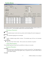
1
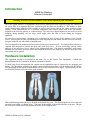
FIBER SIGMA 105 Hillcrest Road Flemington, New Jersey 08822-7173 U.S.A. Tel: +(908) 377-0763 Fax: +(908) 547-0095 E-mail: [email protected] Web: http://www.fibersigma.com STRIP for Windows: CONTROL PROGRAM FOR OPTICAL FIBER COATING STRIP AND PULLOUT FORCE APPARATUS USER’S MANUAL (For STRIP software version 0.19) Version 0.19a, August 2010 Contents Contents................................................................................... 1 Introduction ............................................................................. 2 Hardware Installation .............................................................. 2 Electrical Connections....................................................... 3 STRIP for Windows Software Installation.............................. 3 Running the Software for the First Time ........................... 3 Uninstalling STRIP for Windows...................................... 3 Updating the System Controller Firmware ........................ 3 Quick Start .............................................................................. 4 Stripping Your First Fiber ................................................. 4 The STRIP Windows .............................................................. 4 The Main Window............................................................. 5 Performing an Experiment........................................... 5 Loading Rate Parameters ............................................. 5 Contents Experiment Parameters .................................................5 Data Display Area.........................................................6 Export Data Window..........................................................7 Graph Window ...................................................................7 Set Zero Position Window..................................................8 Options Window.................................................................8 Calculator ...........................................................................8 Hardware Setup Window ...................................................8 Load Cell Calibration...............................................................8 Configuration Files...................................................................8 Troubleshooting .......................................................................8 Missing Features and Known Bugs..........................................8 History......................................................................................8 1 STRIP for Windows User’s Manual Introduction STRIP for Windows Software Version 0.19 Warning: Protective Eyewear Must Be Worn While Operating This Instrument The Fiber Sigma Tensile Test Equipment can be used to measure the force required to strip the coating off an optical fiber or to measure the force required to pull the fiber out of adhesive. The results, to some extent, depend on the adhesion of the coating, as well as other factors, such as the elastic properties of the coating. Such measurements are of practical importance since optical fibers need to be successfully stripped in the field for splicing or connectorizing. The strip force should neither be too small, to avoid stripping during handling, nor too large, which might cause the fiber to break during the stripping operation. For strip force measurement a stripping tool is mounted in place of one of the capstans of the Tensile Tester. Fiber Sigma provides a MicroStrip precision stripping tool and holder, but the end user can easily design a holder for any other kind of stripping tool. The load applied to the stripping tool is measured using a precision load cell. The load/position behavior is captured and analyzed to provide the peak and mean strip force. Several windowing options permit analysis of the strip force over a subset of the load/position data. This permits compliance with certain standard test procedures and also means that insignificant parts of the behavior at the start and end of the experiment can be ignored. Hardware Installation The equipment should be assembled in the same way as the Tensile Test Equipment. Consult the documentation for the Tension for Windows program for details. To make strip force measurements the capstan on the translation stage is replaced by the stripping tool holder. The MicroStrip stripping tool needs a minor modification so that it can be mounted in the holder. The photograph below shows an unmodified tool (left) and a modified tool (right). Approximately 10 mm are removed from the end of the white guide channel. This modification permits the tool to be held in the holder by a pin. The photograph below shows the tool inserted in the holder, as shown below. The knob in the middle of the holder attaches to the pin. The pin has a flat on it which seats firmly against the frame of the stripping tool. STRIP for Windows User’s Manual 2 For pullout force measurements the capstan is replaced by the toggle clamp assembly. The load cell needs to be calibrated. The calibration procedure is the same as that used for the Tensile Test Equipment. Consult the Load Cell Calibration section in the documentation for the Tension for Windows program for details. Electrical Connections Consult the documentation for the Tension for Windows program for details. STRIP for Windows Software Installation Warning: Run Windows Update to get the latest Windows patches before attempting to install STRIP for Windows Warning: Uninstall previous versions of STRIP before installing a newer version Run the SETUP program obtained from the Fiber Sigma website (http://www.fibersigma.com/downloads) or from the distribution CD in the STRIP directory. If you want to use a USB port on your PC for connecting to the System Controller, install the software supplied with the serial to USB adaptor. Running the Software for the First Time Running the STRIP program for the first time is the same as for the TENSION program. Consult the documentation for the Tension for Windows program for details. Uninstalling STRIP for Windows STRIP for Windows can be uninstalled using either one of two methods: 1. Run the Uninstall icon in the Fiber Sigma program folder (Start | Programs | Fiber Sigma). 2. Go to Start | Settings | Control Panel | Add or Remove Software and select STRIP and click Change/Remove. Updating the System Controller Firmware Warning: The Run/Program switch on the System Controller should be left in the Run position at all times except when updating the firmware using the instructions below. Consult the documentation for the Tension for Windows program for details on how to reprogram the System Controller. 3 STRIP for Windows User’s Manual Quick Start Consult the documentation for the Tension for Windows program for information on how to prepare the equipment for use. Add the strip force tool holder or the pullout force toggle clamp as described in the Hardware Installation section. Stripping Your First Fiber Warning: Operating This Equipment Can Be Hazardous Both the operator of the equipment and any other personnel in the same room must wear protective eyewear. The fiber might break during testing in which case it might shatter into several fragments which can have considerable kinetic energy, potentially injuring people not involved with the measurement. 1. Check that the loading rate and experiment parameters are correctly set in the Main Window. 2. Click Load fiber and wait until the translation stage has finished moving. 3. Take a suitable length of fiber, perhaps one meter long. Make sure that the striping tool is clean and free of any coating debris the small brush included with the tool. Insert one end of the fiber into the tool to the desired strip length. This is added by the scale on the white insert. It can be useful to place an ink mark on the insert at the position where the end of the fiber should be. Carefully close the tool and slide it all the way into the tool holder, making sure the fiber pigtail is not tugged. Drop the pin into the hole in the tool mount, then pull the tool out of the mount until it engages with the pin. The flat on the pin should engage with the handles of the stripping tool. 4. Carefully wrap the other end of the fiber around the load cell capstan for two or three turns. The fiber should first contact the capstan along the measurement axis of the load cell. This axis is collinear with the screw attaching the capstan plate to the top of the capstan. When correctly positioned the fiber should contact the rubber tape on the capstan approximately 6 mm from the edge of the tape. 5. Click Strip fiber and wait until strip is finished. The STRIP software will then take a few seconds to upload the force/position data from the System Controller. It will then display the data in the Graph Window. The graph can be reviewed, resized and the data and graph can be copied to the clipboard. The STRIP Windows This section describes the windows in the STRIP program: The Main Window Export Data Window Graph Window Set Zero Position Window Options Window Calculator Hardware Setup Window STRIP for Windows User’s Manual 4 The Main Window This window is at the heart of the program. Experiments are run from this window and other windows are all accessed from here. The main window displays all key experimental parameters. Performing an Experiment Load fiber The translation stage is moved to the zero position ready for loading a fiber into the stripping tool. Strip fiber The capstan and stripping tool are moved apart. Go to Specify a translation stage position in microns. The translation stage will move at its maximum speed. Set Zero position Opens the Set Zero Position window. This is used to reset or check the zero position. Loading Rate Parameters The translation stage/strip tool speed can be specified here in either µm/s or mm/min. Experiment Parameters Pull length This specifies how far the translation stage moves in order to strip the fiber. This length might be a few mm more than the official strip length in order (i) compensate for any slack in the fiber and (ii) ensure complete stripping. Threshold 5 STRIP for Windows User’s Manual Load/position data are captured during the stripping step. These data are used to characterize the strip force by the mean and maximum force. However, if there is any slack in the fiber, the measured force will be zero at the start of the experiment. If the fiber is completely stripped the force will drop to zero at the end of the experiment. If these regions of zero strip force are used to calculate, for example, the mean strip force, the result will be perturbed by the zero force regions which do not include real strip force information. These leading and trailing sections of the force/position trace can be ignored by setting a threshold force which is used to detect the start and end of the strip event. If this threshold force (in newtons, N) is non-zero then STRIP will search the force/position data from the start position until a force greater than the threshold is encountered – all data before this are ignored during the analysis; STRIP will also search the force/position data backwards from the end until a force greater than the threshold is encountered – all data after this are ignored during the analysis. In this way a window is taken from the data for analysis of the strip force. If the threshold load is set to zero, windowing of the data is not performed and all data are used. Analyze from….to Specifications for strip force might require that portions of the strip force/position trace be ignored for analysis. For example IEC 60793-1-32 requires that the first 20% of the data be ignored. The Analyze from .. to parameters are used to define a window in the data used for analysis. The parameters are specified as percentages, so that, for example for the IEC 60793-1-32 specification, the user would set 20 to 100 for these parameters. Note that this window into the data is into the window defined by the threshold load defined above. Specimen number This is the index number for the next specimen to be broken. This index number is the parameter “N” in the first column of the Result Table. Data Display Area The results of the stripping experiment are displayed in the Result Table. They are also saved to the current data file. This section of the Main Window shows the name of the current output file for the results. The file name includes the full path to the file - if the result is too long to fit in the available space part of the path may be replaced by ellipses. In that case, simply hover the mouse over the file name and the complete path and name will be displayed in the “tool tip” which appears when hovering. The Result Table The result table lists all results currently stored in the data file. The table can be configured to your liking and the display can be manipulated in various ways. The Result Table contains the following: The first column is grayed out and can not be edited. This contains the line number in the data file for each row/measurement. Note that even if the table is sorted in some order, the data file contains the data in order of this line number. N sequence number of the measurement max the maximum strip force measured in the window into the force/position data (see the Experiment Parameters section) measured in newtons (N) mean the mean strip force measured in the window into the force/position data (see the Experiment Parameters section) measured in newtons (N) std dev the standard deviation of the strip force measured in the window into the force/position data (see the Experiment Parameters section) measured in newtons (N) v translation stage speed (displayed in both µm/s and mm/min) L strip length (mm) date date at the end of the measurement, format is year/month/day so that sorting in alphanumerically also sorts in date order time time at the end of the measurement comment comments can be inserted in this column STRIP for Windows User’s Manual 6 [from-to]% min This single column contains a variety of parameters that are not normally needed themselves for later data analysis. However, they are included because they are all parameters that might affect the results – they are included so you can check you used the right values for them. They are the Analyze from .. to parameters %) and the threshold load (N). See the Experiment Parameters section for the meaning of these parameters. Result Table Actions Several actions can be used to customize the data display, export the data or add comments. The behavior of the result table is the same as for the TENSION program. Consult the documentation for the Tension for Windows program for details. Export Data Window Consult the documentation for the Tension for Windows program for details. Graph Window The graph window provides a detailed view force/position data captured during the experiment. Only the red part of the trace is used to calculate the maximum, mean and standard deviation of the strip force. The blue sections of the trace, if present, are defined by the Threshold load parameter (defined in the Experiment Parameters section). In the above example the threshold load was set to 0.2 N so that all data at the start and the end are ignored until a force of 0.2 N is detected. The green sections of the trace, if present, are also ignored for the strip force analysis. These sections are defined by the Analyze from .. to parameters (defined in the Experiment Parameters section). In the above example these parameters were set to 20% and 80% so that the first and last 20% of the trace are ignored. The horizontal red lines are the results of analyzing the data drawn in red. The solid lines are the mean (lower) and maximum (upper) strip force. The dotted lines are the mean strip force ± the standard deviation of the strip force. 7 STRIP for Windows User’s Manual Clicking the Copy button copies to the clipboard both the graph (in bit map format) and the data displayed by the graph. Either the graph or the data can be pasted into other applications - which gets pasted depends on the application. For example, Paint pastes the graph while SigmaPlot pastes the data. By default the data are pasted into Excel and Word but the graph can also be pasted using Paste Special. Note that the graph window can be resized to obtain bigger graphs with more resolution. Set Zero Position Window Consult the documentation for the Tension for Windows program for details. Options Window Consult the documentation for the Tension for Windows program for details. Calculator Consult the documentation for the Tension for Windows program for details. Hardware Setup Window Consult the documentation for the Tension for Windows program for details. Load Cell Calibration The calibration procedures for the load cell are identical to those for the TENSION program. Consult the documentation for the Tension for Windows program for details. Configuration Files Configuration files are plain text files that contain settings for various program parameters. Reading a configuration file will automatically set the values for the defined parameters. They can be used to quickly set several parameters at once. For example, you could create a file IEC60793-1-32.INI which would specify parameters that are compatible with that standard test procedure: ExptSpeed 8333.33 PullLength 30 StartAnalysis 20 StopAnalysis 100 The configuration files can be constructed using a plain text editor such as NotePad. As a starting template, you can create a file containing all available configuration parameters using the write configuration file option. You can then delete irrelevant parameters and adjust others as necessary. A complete list of Configuration File Parameters follows: Configuration File Parameters The available configuration parameters are listed below, together with their default values. Note however, that many parameters are saved when the STRIP program is closed. ExptSpeed 8333 PullLength 30 SpecimenCount 1 ThresholdForce 0 Specifies the translation stage speed in µm/s used during the strip force measurement. Specifies the distance in mm the translation stage should move the stripping tool during the measurement. Sets the index number of the next fiber to be broken. Specifies the threshold force in newtons which is used to ignore data at start STRIP for Windows User’s Manual 8 and end of the measurements. All data are used if this parameter is set to zero. StartAnalysis% 20 These two parameters express as a percentage the portion of the force/position StopAnalysis% 100 data that are analyzed for the strip force. HiCurrRate 10 When the translation stage is moved at a speed (µm/s) greater than the value defined by this parameter then the motor current is increased for the move. If the speed is less than this value, STRIP will drop the current to the lower standby current to avoid heating effects in slow, long-duration tests. The motor current will only be low if the Motor Current switch on the Stepper Motor Drive is set to remote. ReverseSense Set to false for normal operation. When set to true the sense of the translation stage/motor rotation are reversed. This can be used if custom fixtures are False mounted at the motor end of the translation stage instead of the other end. Note that the position displayed by the Stepper Motor Drive will be the negative of the value shown by STRIP. Noisy True If this parameter is set to true, then the System Controller clicks when each step is taken by the motor. This provides auditory feedback on the progress of an experiment. If the clicking/buzzing is annoying, set this parameter to false. Troubleshooting This section will include some common problems encountered by users, when such problems become apparent. Missing Features and Known Bugs Missing Features Automated updating of System Controller firmware Reset all configuration parameters to defaults Known Bugs Please report any bugs or errors. Please also suggest any way in which the software can be improved. History Version 0.19 No significant changes. Version 0.18 Fixed “subscript out of range” bug when starting a calibration (introduced in version 0.17). Version 0.17 Maintenance release. Version 0.16 Fixed bugs associated with load cell calibration window. Version 0.15 Fixed additional problems with how Greek characters display in Asian versions of Windows. Further improvements have been made to sorting the Results Table. Sorting multiple columns can be performed by sorting the individual columns in sequence. Sorting by date also sorts by time so that the results are sorted into exact chronological order. 9 STRIP for Windows User’s Manual The Motor Moving window now has a check box which locks the keyboard so that the motor can not be stopped by accidentally entering a keystroke. This helps avoid accidents during long duration experiments. Version 0.14 STRIP can be run without a System Controller attached – useful for exporting data or using the calculator. Detection of the System Controller has been improved. Improved sorting of the data grid. All program parameters can now be reset to their default values from the Options window. Fixed a problem with editing comments in the data grid. Version 0.13 Initial release. STRIP for Windows User’s Manual 10