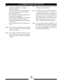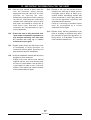
1
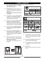
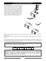
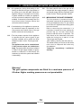
INSTALLATION AND
MAINTENANCE MANUAL
COMBINATION OVEN
WITH AND WITHOUT STEAM GENERATOR
GB
Technical service
90023730rev01
CONTENTS
1 •
2 •
3 •
4 •
5 •
6 •
7 •
8 •
9 •
10 •
11 •
12 •
13 •
14 •
GENERAL REMINDERS
TECHNICAL DATA
SPECIAL REQUIREMENTS FOR THE INSTALLATION SITE
STATUTORY REQUIREMENTS, TECHNICAL REGULATIONS AND DIRECTIVES
POSITIONING
ELECTRICAL CONNECTIONS AND EQUIPOTENTIAL BONDING
POINTS TO REMEMBER WHEN MAKING THE ELECTRICAL CONNECTION
WATER AND DRAIN CONNECTIONS
VENTS
GAS CONNECTION PROCEDURES
OPERATING AT THE RATED HEAT OUTPUT
COMMISSIONING AND TESTING
IMPORTANT INFORMATION FOR THE USER
INSTALLATION DIAGRAMS
Page
3
4
6
7
7
9
9
10
12
12
14
16
17
18
MODELS
4 x GN 2/3
5 x GN 1/1
6 x GN 1/1
7 x GN 1/1
7 x GN 2/1
10 x GN 1/1
10 x GN 2/1
20 x GN 1/1
20 x GN 2/1
VERSIONS
M - Standard electromechanical devices with manual controls, humidifier and lighting.
D - Manual controls with electronic control, humidifier, manual vent, lighting and double-glazed door.
P - Programmable electronics with control for automatic humidity, twin speed, core probe, lighting and
integrated washer unit.
T - Scroller with automatic humidity control, twin speed, MULTIPOINT core probe, PLUS FUNCTION,
lighting and integrated washer unit.
(KL automatic washing system on request)
The manufacturer accepts no liability for any inaccuracies in this manual
attributable to printing or copying errors. We reserve the right to modify
our products as we deem fit, without impairing their basic features.
The reproduction or copying of any part of this manual by any means
whatsoever is strictly forbidden unless authorized previously in writing by
the manufacturer.
ALI S.p.A. - 01.09.2004
2
90023730rev01
1 •GENERAL REMINDERS
1.1
• The oven must be installed, commissioned
and maintained only by a Lainox
authorized service agent.
1.2
• Carefully read the directions given in this
manual; they contain important information on
safety during installation, operation and
maintenance.
Keep this manual in a safe place for future
consultation!
1.3
• This appliance must be put only to the use
for which it is specifically intended, i.e.
cooking foods; any other type of use is
improper and therefore dangerous.
1.4
• Having removed the packing check that the
appliance is not damaged in any way.
If in doubt, proceed no further with installation
of the appliance and contact the Lainox
Customer Service or your dealer immediately.
1.5
1.6
• Example of a data plate:
• Packing materials must be disposed of in
conformity with local regulations. This
normally means that the different materials
are sorted according to type and collected as
urban refuse.
1.9
• Before positioning and connecting the
appliance, check that the utilities (electrical
power, water and gas supplies) are as
indicated on the data plate.
The data plate is on the right-hand side, at
the bottom.
• Packing materials are potentially dangerous
and must not be left where children can
play with them.
'
(
!"#
$ %&
• The positions of the inlet and drain
connections are clearly labelled. For further
details, see the installation diagram attached
to this manual.
1.10 • In the event of breakdown or faulty operation,
switch off the oven immediately!
1.11 • During installation and/or maintenance work it
is recommended you wear gloves to protect
your hands.
1.12 • Safety sticker
• Maximum height for inserting containers with
liquids.
1600 mm (63 inch)
1.7
1.8
3
90023730rev01
2 • TECHNICAL DATA
TABLE 1: GENERAL DATA - ELECTRIC OVENS
Model
Supply
voltage
Frequency
Total power
input
Amps
Chamber
power
Boiler
power
Motor
Oil-proof
connecting
cable
4 x GN 2/3
3N AC 400 V
3 AC 230 V
AC 230 V
50 Hz
3.25 kW
5
8
14
3.15 kW
-
1 x 0.20 Kw
5 x 1 mm2
4 x 1 mm2
3 x 1.5 mm2
5 x GN 2/3
3N AC 400 V
3 AC 230 V
AC 230 V
50 Hz
6.25 kW
9
16
27
6 kW
-
1 x 0.20 Kw
5 x 1 mm2
4 x 1.5 mm2
3 x 4 mm2
2x
5 x GN 1/1
3N AC 400 V
3 AC 230 V
50 Hz
12.5 kW
18
31
6 + 6 kW
-
2 x 0.20 Kw
5 x 2.5 mm2
4 x 4 mm2
6 x GN 1/1
7 x GN 1/1
3N AC 400 V
3 AC 230 V
AC 230 V
50 Hz
8 kW
12
20
35
7.5 kW
7,5 kW
1 x 0.25 Kw
5 x 1.5 mm2
4 x 2.5 mm2
3 x 6 mm2 2)
7 x GN 2/1
10 x GN 1/1
3N AC 400 V
3 AC 230 V
50 Hz
16 kW
23
40
15 kW
15 kW
1 x 0.55 Kw
5 x 2.5 mm2
4 x 6 mm2
10 x GN 2/1
3N AC 400 V
3 AC 230 V
50 Hz
31 kW
45
78
30 kW
30 kW
1 x 0.55 Kw
5 x 10 mm2 3)
4 x 25 mm2
20 x GN 1/1
3N AC 400 V
3 AC 230 V
50 Hz
31.8 kW
46
80
30 kW
30 kW
2 x 0.55 Kw
5 x 10 mm2 3)
4 x 25 mm2
20 x GN 2/1
3N AC 400 V
3 AC 230 V
50 Hz
61.8 kW
89
155
60 kW
60 kW
2 x 0.55 Kw
5 x 25 mm2
2x (4 x 25 mm2)
*) 2 power cables - 1) min Ø 12 mm - 2) max Ø 18 mm - 3) min Ø 26 mm - 4) max Ø 44 mm
Caution: The residual current device to be installed between the mains and the appliance
must be sized for a leakage of 1 mA x kW of power installed.
TABLE 2: GENERAL DATA GAS OVENS
Model
Supply
voltage
Frequency
Input
Motor
Oil-proof
connecting
cable
Gas power
Gas
connection
5 x GN 1/1
AC 230 V
50 Hz
0.25 kW
1 x 0.20 Kw
3 x 1 mm2
7.5 kW
1 x R 1/2"
6 x GN 1/1
AC 230 V
50 Hz
0.5 kW
1 x 0.25 Kw
3 x 1 mm2
9 kW
1 x R 1/2"
10 x GN 1/1
AC 230 V
50 Hz
1 kW
1 x 0.55 Kw
3 x 1 mm2
18 kW
1 x R 1/2"
10 x GN 2/1
AC 230 V
50 Hz
1 kW
1 x 0.55 Kw
3 x 1 mm2
27 kW
1 x R 1/2"
20 x GN 1/1
AC 230 V
50 Hz
1.8 kW
2 x 0.55 Kw
3 x 1.5 mm2
27 kW
1 x R 1/2"
20 x GN 2/1
AC 230 V
50 Hz
1.8 kW
2 x 0.55 Kw
3 x 1.5 mm2
54 kW
1 x R 3/4"
4
90023730rev01
2 • TECHNICAL DATA
TABLE 3: GENERAL WATER DATA
Model
Water
pressure kPa
6 x GN 1/1
7 x GN 1/1
200 - 500
10
2 x R 3/4" (1)
7 x GN 2/1
10 x GN 1/1
200 - 500
19
2 x R 3/4" (1)
10 x GN 2/1
200 - 500
30
2 x R 3/4"
20 x GN 1/1
200 - 500
37
2 x R 3/4" (1)
20 x GN 2/1
200 - 500
68
2 x R 3/4"
6 x GN 1/1
10 x GN 1/1
GAS
WITHOUT STEAM GENERATOR
Softened water
consumption
max.l/h
10 x GN 2/1
20 x GN 1/1
200 - 500
200 - 500
200 - 500
200 - 500
8
17
24
24
48
Model
4 x GN 2/3
200 - 500
4
2 x R 3/4"
5 x GN 1/1
200 - 500
8
2 x R 3/4" (1)
2x
5 x GN 1/1
200 - 500
8+8
2 x R 3/4"
(1)
6 x GN 1/1
200 - 500
8
2 x R 3/4"
(1)
15
2 x R 3/4" (1)
(1)
(1)
2 x R 3/4"
(1)
2 x R 3/4"
(1)
2 x R 3/4"
(1)
2 x R 3/4"
(1)
2 x R 3/4"
(1)
(1)
Water
connection
(1)
7 x GN 1/1
GAS
20 x GN 2/1
200 - 500
Softened water
Water
pressure kPa consumption
max.l/h
Water
connection
ELECTRIC
ELECTRIC
WITH STEAM GENERATOR
7 x GN 2/1
10 x GN 1/1
200 - 500
10 x GN 2/1
200 - 500
15
2 x R 3/4" (1)
20 x GN 1/1
200 - 500
30
2 x R 3/4" (1)
20 x GN 2/1
200 - 500
30
2 x R 3/4" (1)
5 x GN 1/1
200 - 500
8
2 x R 3/4" (1)
6 x GN 1/1
200 - 500
15
2 x R 3/4" (1)
10 x GN 1/1
200 - 500
22
2 x R 3/4" (1)
10 x GN 2/1
200 - 500
22
2 x R 3/4" (1)
20 x GN 1/1
200 - 500
30
2 x R 3/4" (1)
20 x GN 2/1
200 - 500
44
2 x R 3/4" (1)
The ovens are equipped with two water inlets, one for non-softened cold water and the other for hot water (max. 50 °C) or softened cold water.
TABLE 4: FLUE GAS EXTRACTION DATA (TYPE B13)
Models
Flue liner
pressure
Volumetric
mass
Flue gas
temperature
6 x GN 1/1
7 x GN 1/1
10 x GN 1/1
10 x GN 2/1
20 x GN 1/1
20 x GN 2/1
- 1.4 Pa
- 1.4 Pa
- 3.0 Pa
- 3.0 Pa
-
16.0 g/sec.
22.0 g/sec.
27.0 g/sec.
27.0 g/sec.
-
130 ˚C
155 ˚C
200 ˚C
200 ˚C
-
5
90023730rev01
3 • SPECIAL REQUIREMENTS FOR THE INSTALLATION SITE
3.1
• The room where the oven is to be fitted has
to be well ventilated with all the openings
required for rooms with gas installations
(see specific regulations).
3.2
• In addition, it is good policy to locate the
appliance under an extractor hood so that
cooking vapours can be removed rapidly
and continuously.
3.3
• The room must have a flue gas extraction
stack (appliances with installation type
B13), or a suitable flue gas extraction
system fitted with all relevant safety
devices (appliances with installation type
B23). Further details are given under the
heading: "Gas connection procedures".
Check with the appropriate agency whether
or not special authorization is required for
the emission of flue gases into the
atmosphere.
3.4
• Current CEI (Italian Electrotechnical
Committee) regulations require the
installation of a multiple pole switch
between the oven and the electrical power
supply; the switch must have a contact gap
of at least 3 mm on each pole.
3.5
• The oven needs two water supplies, one of
which need not be softened, but must
necessarily be cold (for condensing
steam). The other supply, serving the
vaporizer, must incorporate a softener with
suitable flow and pressure specifications
(see technical data and water connections
heading). A shutoff valve must be installed
on each of the water supply pipelines to
the appliance.
3.6
• The room must have a water drain in a
good position for the oven to be installed,
its specifications are given under the
heading “Water and drain connections” in
this manual.
3.7
• The gas supply plumbing must be installed
in accordance with current regulations,
adopting pipe sections and pressures
suitable for the appliance (see technical
data and gas connections heading).
A fast acting shutoff valve must be installed
on the gas inlet line to the appliance. It is
absolutely essential that this valve should
be specified to current standards and type
test approved.
3.8
• The electrical isolating switch and the
water and gas shutoff valves must all be
located near to the appliance, within easy
reach for the user.
6
90023730rev01
4 • STATUTORY REQUIREMENTS, TECHNICAL REGULATIONS AND DIRECTIVES
Throughout installation it is vital to observe
the following requirements:
4.1
• any health and hygiene standards
applicable to kitchens and eating places;
4.7
• the regulations of the electrical power
supply company or agency;
4.2
• local and/or territorial building regulations
and fire prevention standards;
4.8
• any other local regulations.
4.3
• current accident prevention guidelines;
4.4
• CEI requirements relating to electrical
systems;
4.5
• UNI-CIG 8723 Standard “Gas systems for
appliances used in professional kitchens
and communal facilities”;
4.5
• the regulations of the gas supply company
or agency;
5 • POSITIONING
5.1
• To position the appliances, it is recommended
to use the mount offered by the manufacturer;
should you want to do things differently, it is
necessary to take account of the weight of the
appliance.
5.2
• Before manoeuvring the oven into the
selected position, attach the water inlet hoses
and waste pipe to the relative connection
points (refer to headings describing the water
and drain connections).
5.3
obstruct the openings and slots in the casing
as they disperse the heat in the electric
component compartment.
Keep strictly to the installation diagrams.
5.4
• Once the appliance is installed, the electrical
power cable must be protected, and never
stretched or tugged.
5.5
• The appliance must be level: any difference in
level or sloping of the supporting surface
should be eliminated. Differences in level or
sloping negatively affect oven operation.
• The distances from other appliances or from
adjacent walls that must be left to allow
access for servicing operations will be found
on the installation diagram for the oven to
connect. In the event of the oven being
installed directly against an inflammable wall,
suitable heat insulation must be provided.
Current fire regulations should be
meticulously observed and respected. Do not
7
90023730rev01
5 • POSITIONING
5.6
• Remove all packing materials and peel away
the protective plastic film from all external
surfaces of the oven.
5.7
• For free-standing models, the appliance needs to
be levelled: small differences in level of the
supporting surface can be eliminated with the
adjustable feet (by screwing or unscrewing
them). A significantly uneven or sloping stance
can affect the operation of the oven adversely.
For models equipped with a pan trolley, it is
necessary to pay special attention when levelling.
5.8
• Lining up the pan trolleys 20 x 1/1 GN
and 20 x 2/1 GN. If the floor is not level, a
remedy must be found using an access ramp
with a maximum gradient of 4° (not included in
the supply).
If there is an outlet grate in front of the
appliance, it is necessary to fit runners in the
pan trolley entry area.
OK
OK
201 - 202
X = 200 mm
Y = 300 mm
8
90023730rev01
6 • ELECTRICAL CONNECTIONS AND EQUIPOTENTIAL BONDING
6.1
• As this oven is a type X appliance (oven
without power cable and plug), the cable and
other hardware needed to make the
connection to the electrical power supply must
be provided by the installer. The cable must
satisfy the requirements indicated in table 1
“General data”. As already mentioned, the
oven must be connected to the power supply
by way of a multiple pole main isolating switch
ensuring a gap between open contacts of at
least 3 mm on each pole.
6.2
• To gain access to the AC mains connection
terminal board, the right hand panel of the
casing must be removed by undoing the fixing
screws (all models).
6.3
• The cable must be fed in from beneath the
clamp. The individual wires are then fastened
to the corresponding terminals of the terminal
board. The earth wire must be longer than the
other wires, so that in the event of the cable
being jerked or the clamp broken, the live
wires will disconnect first.
Check the efficiency of the isolating switch.
6.4
• The oven must be kept in an equipotential
system. This connection is made by wiring a
conductor of nominal cross section 10 mm2 to
the corresponding terminal at the back of the
oven, which is marked with the internationally
recognized symbol.
All appliances in the room are bonded in this
way and connected to the earth system of the
building.
6.5
• The electrical safety of this appliance can be
guaranteed only when it is connected correctly
to an efficient earth system, in compliance
with current standards.
7 • POINTS TO REMEMBER WHEN MAKING THE ELECTRICAL CONNECTION
7.1
7.2
• As all ovens of the series are fitted with an
alternating fan motor (clockwise and
anticlockwise rotation), there is no need for
the fan to rotate in any particular
direction.
Simply
verify,
when
commissioning the appliance, that the fan
is balanced and rotates freely.
Warning: the 20 x GN 1/1 and 20 x GN 2/1
models are equipped with two motors.
7.3
• This trouble is indicated:
On gas models mechanical version by the
burner ignition reset button, which is lit up.
On gas models electronic version via the
electronic card.
7.4
• Check also that the neutral registers zero
potential when tested. If not, the fault
already described in point three of this
section will occur. In this eventuality, consult
the installer of the building's electrical
system.
• When making the electrical connection you
need to take care that the neutral pin of the
terminal block corresponds to the neutral
wire of the supply line. If this connection is
not made correctly, the burners will not be
able to operate.
9
90023730rev01
8 • WATER AND DRAIN CONNECTIONS
supplying water that is too softened or too
aggressive, and scaling in the oven and in
the water system in the case of supplying
water that is too hard.
Hardness: between 3° and 6° TH
PH:
greater than 7.5
Chlorides: less than 30 ppm
These values are important for ensuring
that the water used by the appliance is
suitably treated!
8.1 • WATER PRESSURE
The pressure of the water in the network
must be between 200 and 500 kPa, as
already stated under the heading
“Technical Data”. If the supply pressure is
higher than this, a pressure reduction valve
must be installed between the oven and
the main.
8.2 • WATER CONNECTIONS TO THE
BOILER (IF APPLICABLE) AND
VAPORIZER
The water supplied to the vaporizer must
be either cold and softened or hot (max
50 °C), as described below. The water
connection is R 3/4”. The hose for
connection to the water supply must be
provided by the installer. A shutoff valve
must be installed on the line between the
oven and the supply.
8.4 • WATER CONNECTIONS FOR
CONDENSING STEAM
The water used for condensing steam need
not be softened, but must necessarily be
cold. The water connection is R 3/4”. The
hose for connection to the water supply
must be provided by the installer. A shutoff
valve must be installed on the line between
the oven and the supply.
8.3 • WATER SPECIFICATIONS
The characteristics of the water must come
within the limits given below, in order to
prevent both corrosion, which is extremely
damaging for the appliance, due to
10
90023730rev01
8 • WATER AND DRAIN CONNECTIONS
8.5 • DRAINING
The water is drained off by gravity through
a heat-resistant pipe DN 50 (not flexible),
maximum length 2 m, installed at an angle
of no less than 4°.
Mean temperature of the drain water:
65 °C.
Fig. 1
For the range with the drain as per fig.1 it is
possible to make a direct connection with an air
trap, without fitting a drain cup, as the drainage
manifold system has an internal air drop (Fig. 2).
With a drain on the floor without an air trap it is
necessary to have an outlet clearance of 2 cm
(Fig. 3).
Fig. 2
Range “The Cube”
Fig. 3
For the remaining models it is imperative to fit a
drain cup to ensure a minimum air drop of 25 mm.
between the appliance's plastic drain elbow and
drain line. A direct connection is not
permissible.
Min. 4
25 mm.
Max. 200 cm
WARNING:
The drain line must be outside the perimeter of the oven.
It is prohibited to reduce the drain diameter.
11
90023730rev01
9 • VENTS
9.1
• Under no circumstances must vents A
and B be shut, blocked or ducted into
other pipes.
A - Vent to extract vapours from the oven
B - Safety vent
A
B
10 • GAS CONNECTION PROCEDURES
10.1 • GAS CONNECTION
The section of the gas supply pipe must be
chosen according to the type of gas and the
consumption of the appliance to be
connected. The system must be designed
and installed in accordance with current
regulations. The gas connection on the
oven is R 1/2” or R 3/4”, and this
section must never be reduced.
A fast acting shutoff valve must be installed
on the gas inlet line to the oven. The valve
must be type test approved in accordance
with current regulations.
The connection to the gas main can be
permanent or detachable; if flexible metal
tube is used, this should be made of a
stainless and corrosion resistant material
(rubber hose is not recommended).
If when making the connection you use any
sealing materials, they must be type test
approved for this purpose.
10.3 • EXHAUSTING FLUE GASES
Model with 5, 6 and 7 pans GN 1/1
Since this appliance due to its capacity has
installation type A3, it is not necessary to
connect it to a stack for extracting the flue
gases. The flue gases can be exhausted into
the installation room. It is especially important
to have good, continuous ventilation!
Remaining models
As these ovens have a power rating of
>14 kW, type B installation is required. The
installer must select one of the methods
described below, according to the design of
the building and of the room where the
appliance is sited. The diameter of the flue
pipes must be as indicated in the installation
diagrams.
Warning:
flue gases may reach temperatures of
400 °C!
10.2 • LEAK TEST
All connections between the mains and the
appliance must be tested for leakage. The
recommended method is to use a proprietary
leak detection spray; alternatively, a noncorrosive foamy liquid of any general
description can simply be brushed onto the
fittings: whichever method is used, no
bubbles should appear.
Never under any circumstances test for
gas leaks with a naked flame!
Fumes must never be ducted away
utilizing an extraction system!
Clear the gas supply system of any
machining debris before connecting the
oven!
12
90023730rev01
10 • GAS CONNECTION PROCEDURES
Installation type B13
Extraction with natural draught fitted with a damper
and a heat-resistant pipe (see "Flue gas
temperatures" in Table 4 under the heading
“Technical Data”) connected to the stack. Never
under any circumstances must flue gases be ducted
away directly utilizing a mechanical extraction
system. Selecting this type of installation the oven
must be fitted with the damper, as shown in the
drawing. If the oven is equipped with an adaptor
collar for standard size flue pipes, fit the adaptor.
Hood filter
Suction hood
Ducted
ceiling
Note: It is the installer's responsibility to ensure that the flue extension pipe has been correctly and
securely fitted.
Note: From the floor to the top limit of the flue gas extraction pipe (extension) there must be a minimum distance
of 1.80 m.
Where extraction systems are selected for type B13 and B23 installations, these must be properly sized
and specified with at least one interlock device that will shut off the gas supply to the oven automatically in
the event of the extractor system failing to operate.
After installation, the installer must update the data plate by ticking the box, corresponding to
the type of installation made, with an indelible marker pen.
)!
*!
*!
The manufacturer accepts no liability for any damage or malfunctioning of the appliance
attributable to the absence or inadequacy of earthing systems, to the incorrect arrangement or
installation of auxiliary systems, also to incorrectly made connections or to non-compliance of
the building's electrical system with current regulations.
13
90023730rev01
11 • OPERATING AT THE RATED HEAT OUTPUT
11.1 • All appliances, during final testing in the
factory, are fitted for the type of gas shown on
the sticker next to the data plate. Should the
appliance fitting not correspond to the family
of gases available on location, the appliance
must be converted to adapt to the type of gas
available. If conversion is necessary, then you
must inform Lainox Customer Service and
refer to the technical manual.
11.2 • Commissioning of the appliance to operate at
the rated heat output is dependent on the
inlet pressure and calorific value of the gas
and the correct amount of primary air.
11.3 • The inlet pressure required for the appliance
to operate with the various types of gas
typically available will be within the limits
indicated in table 6 of the “Tecnical gas data”
booklet.
The appliance must not be commissioned
if inlet pressure values are outside these
limits. If pressures differ from those indicated
in Table 6, the gas supply company or agency
should be contacted, or alternatively the
contractor by which the system was installed
in the building.
11.4 • The lower calorific value of the gas can be
checked with the supply company or agency,
and should comply with the information given
in table 5 of the “Tecnical gas data” booklet.
11.5 • MEASURING THE INLET PRESSURE
The inlet pressure is measured using a
manometer connected to the pressure tap (3)
of the gas adjustment valve. To gain access
to the valve, the right-hand side casing panel
has to be removed.
Before connecting the manometer it is
necessary to loosen the screw sealing the
pressure tap (3). You then measure the
pressure with the burner in operation. The
value shown on the manometer must come
within the limits given in table 6 “of the
“Tecnical gas data” booklet.
After checking, carefully close the screw (3).
The sealed screws you can see on the valves
must never be tampered with under any
circumstances.
Tampering immediately invalidates
warranty!
Warning!
The gas system components are fitted for a maximum pressure of
65 mbar. Higher working pressures are not permissible.
14
90023730rev01
11 • OPERATING AT THE RATED HEAT OUTPUT
CHECKING NOMINAL HEAT CAPACITY
Check the depth of the screw "A" in
accordance with table 5 of the “Tecnical gas
data” booklet,using a gauge.
Short the two terminals "B" and "C" on the
control card - see photo
Check that the burner fan speed, using a
frequency meter connected to terminals "D"
and "E" as in the photo, corresponds to the
data given in table 5 of the “Tecnical gas data”
booklet.
Set 180 °C convection cooking at low speed
(where applicable), otherwise at normal speed.
Check the speed at position "IGN", with
terminals "B" and "C" shorted.
After testing, take off the short.
Check the speed on position "MIN".
Set the normal speed and check the speed at
position "MAX".
Check the combustion, CO (ppm) and CO2 (%)
values, with an appropriate instrument:
Start the oven working, 180 °C convection
mode, open the door and short the micro-door
with a magnet fixed with tape, the oven restarts
and wait for approximately 5 minutes.
Position the flue gas collection probe in the flue
gas outlet pipe (chamber and boiler).
The CO2 must be for:
Natural gas between 9% and 10.5%
L.P.G.
between 11% and 13%
The CO must be no greater than 300 ppm
(measured).
Carry out the test in both convection and steam
mode.
If these readings are outside the ranges,
proceed as stated in the technical manual.
For the conversion from natural gas to LPG, or
vice versa, proceed as described in the
technical manual.
Reading in:
D-E = Hz (0-200Hz)
D-F = VDC (0-6 VDC)
D
F
E
IGN
MIN
MAX
A
C
3
B
Conversion: As mentioned above, every appliance is factory set to burn the type of gas
specified, it may become necessary nonetheless to convert the appliance from one type of gas
to another. Therefore, only personnel authorized by the company and belonging to the technical
service who have the corresponding technical handbook can do this work.
15
90023730rev01
12 •COMMISSIONING AND TESTING
12.1 • Check the appliance and the entire
installation straight after connecting.
Check in particular:
• there are no traces of the protective film on
the outside walls and the oven is empty;
• all the vents are clear;
• the connections are made as required and
instructed in this handbook;
• all the safety requirements of the current
standards, laws and directives are met;
• there is no leakage from the gas and water
connections;
• water drainage and flue gas extraction are
clear.
12.2 • Now proceed to light the oven as directed
in the user manual, checking the smooth
ignition of the burner.
12.4 • Carefully refit the right-hand side that was
removed for the above work.
12.5 • For additional certainty that the appliance
is operating correctly, carry out a
volumetric measurement of the quantity of
gas consumed. The meter will show how
much gas has been consumed over a
given period of time, and this value can be
checked against the values given in
Table 5 of the “Tecnical gas data” booklet.
12.6 • The test report must be completed in full
and submitted to the customer, who should
then sign in acceptance. With effect from
this moment, the appliance is covered by
the manufacturer's warranty.
12.3 • You should moreover check that the
silicone joints and sleeves of the water
circuit (oven vent, oven outlet, drip tray) do
not leak.
16
90023730rev01
13 • IMPORTANT INFORMATION FOR THE USER
13.1 • With the user manual to hand, show the
user the functions, safety devices,
appropriate use and, above all, the time
intervals for servicing the oven.
Maintenance operations include cleaning
the burners, inspecting the combustion
chamber and cleaning the various ducts
and pipes, and should be carried out at
least once a year. With this in mind,
customers are recommended to sign a
service agreement.
13.2 • Ensure the user is fully aware that such
repair and/or maintenance operations as
may become necessary over time must
be carried out only by a Lainox
authorized service agent.
13.5 • Explain to the user that certain faults in
operation are often due to simple errors or
oversights such as failure to switch on or
connect utilities. Accordingly, kitchen staff
should be trained in such a way that they
can use the appliance confidently and
understand how it operates.
Faults of a recurring or persistent nature
must be investigated by a Lainox
authorized Service Agent.
13.6 • Explain clearly that any alterations to the
room or changes in ventilation may affect
the operation of gas-fired appliances. In
these cases, it is advisable to have the
oven functions checked over.
13.3 • Explain clearly to the user that in the event
of breakdown or faulty operation, all
connected utilities (water, electricity and
gas) should be shut off immediately.
13.4 • Keep the installation manual and the wiring
diagram for future reference.
Explain to the user that the user manual
supplied with the oven must be kept near
the oven in a place where it can be seen. It
is good policy to make a note, in the user
manual, of the name and contact numbers
of the selected Service Agent.
17
90023730rev01
14 • INSTALLATION DIAGRAMS
25
50
DISTANCES TO OBSERVE
500
We recommend keeping a distance
of 500 mm on the right-hand side
in order to carry out maintenance
work.
DO NOT INSTALL APPLIANCES
WITH A SOURCE OF HEAT ON
THE RIGHT-HAND SIDE OF THE
OVEN
CAUTION: if the ambient
temperature to the right of the
appliance is too high, the oven will
stop for reasons of safety.
Minimum distance from sources of
heat on the right-hand side:
400 mm.
400
18
90023730rev01
NOTES
19
90023730rev01
NOTES
20
90023730rev01
NOTES
21
90023730rev01