1
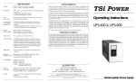
TSi POWER
Operating Instructions
UPS-10000/1000B
16000/EXT-8000
16000
UPSTORS
INDICA
REMOTE
STATUS
G
BAT CHR
INV ON
AC ON
MAX
M
TE
REMO
ALAR
POWER
UT
OUTP
ENABLE
UT
OUTP
ERY
BATT
ON
OTE
REM
BLE
DISA
MAL
NOR
OFF
Uninterruptible Power Supply
LOAD
AGE
VOLT
PPLY
R SU
AGE
VOLT
MIN
PTIBLE
ERRU
UNINT
POWE
SAVE THESE INSTRUCTIONS
This Manual Contains Important Safety Instructions.
CONSERVER CES INSTRUCTIONS
Cette Notice Contient Des Instructions Importantes
Concernant La Sécurité.
This manual contains important instructions for models UPS-10000, UPS-16000
and EXT-8000 that should be followed during installation and maintenance of
the UPS and batteries.
Nominal Battery Voltage of the battery supply inside the UPS and Battery
Extension Unit is 48 volts.
When you are using the rack, cabinet or wall mounting kits, please see the section
on Installation Procedure for Mounting Kits for important safety information.
IMPORTANT NOTICE FOR SERVICING PERSONNEL
A. Servicing of batteries should be performed or supervised by personnel knowledgeable of batteries and the
required precautions. Keep unauthorized personnel away from batteries.
B. When replacing batteries, use the same number and the following type batteries: SEALED LEAD-CALCIUM.
C. CAUTION — Do not dispose of battery or batteries in a fire. The battery may explode.
D. CAUTION — Do not open or mutilate the battery or batteries. Released electrolyte is harmful to the skin and
eyes. It may be toxic.
E. CAUTION — A battery can present a risk of high short circuit current. The following precautions should be
observed when working on batteries:
1. Remove watches, rings, or other metal objects.
2. Use tools with insulated handles.
Table of Contents
Quick Installation Guide......................................................................... 1
Front Controls, Functions & Indicators .................................................. 2
Rear Controls & Functions ..................................................................... 3
EXT-8000 Controls, Functions & Indicators .......................................... 4
About Your UPS...................................................................................... 5
Operating Instructions ............................................................................ 6
Network Installation & Alarm Interface .................................................. 8
Remote UPS Access ................................................................................ 9
Serial RS-232 Communications ............................................................ 10
Backup Time Chart ............................................................................... 12
EXT-8000 Battery Extension Units ....................................................... 13
Troubleshooting and Maintenance ........................................................ 14
Specifications ........................................................................................ 15
Installation Procedure for Mounting Kits .............................................. 17
i
UPS-10000, 16000 & EXT-8000 Operating Instructions
Quick Installation Guide
To get the UPS up and working immediately, please follow these instructions:
¨ Unpack the UPS from the box. Save the packing material for future
use.
CAUTION: You should not attempt to
carry the UPS by yourself. Ask at
least one other person to help you.
¨ Place the UPS at a convenient location, within 6 feet of an electrical
outlet and near the equipment you want backed up. Be careful, it’s
heavy!
¨ Plug the AC cord into a properly grounded, 3-prong, 120V/60Hz 15A
electrical outlet.
¨ Plug in your equipment to the outlets provided at the rear of the UPS.
Please, no refrigerators or space heaters!
¨ Remove the tape from the large power switch at the front of the UPS,
and turn the UPS on with the power switch. After an initial delay of
about 5 seconds, all your equipment hooked up to the UPS should be
ready to power up.
For more information about the
bargraph displays, see page 7.
¨ As a quick check, confirm that the top green bargraph shows between 4
and 6 light segments turned on, and that the middle red bargraph
shows at least 5 light segments turned on.
Congratulations! You’ve already taken a large step toward protecting your
valuable equipment from potential power problems. We suggest however
that you read the rest of this manual to derive the most benefit from your
investment in TSi Power’s UPS’s. If you’ve encountered any problems in
this quick installation procedure, please read on. You can also refer to the
troubleshooting guide on p. 14.
Quick Installation Guide
1
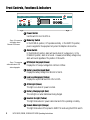
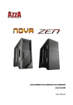
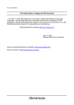
Front Controls, Functions & Indicators
MODE
NORMAL
POWER
REMOTE
ALARM
S TAT U S
ON
ENABLE
DISABLE
OFF
B
A
C
D
E
F
I N D I C ATO R S
min
UPS-16000
max
OUTPUT
VOLTAGE
BATTERY
VOLTAGE
OUTPUT
LOAD
AC ON
BAT CHRG
INVON
REMOTE
G H I J
UNINTERRUPTIBLE POWER SUPPLY
A Power Switch
Use this switch to turn the UPS on.
See p. 9 for more ¨
information about
Remote UPS Access.
B Mode Key Switch
In the NORMAL position, UPS operates normally. In the REMOTE position,
power is supplied to the equipment only when the telephone line is active.
C Alarm Switch
In the ENABLED position, alarm will sound when AC outage occurs. In the
DISABLED position, alarm is not sound. However, when battery voltage is low,
alarm will sound regardless of the position of this switch.
See p. 7 for more ¨
information about UPS
status bargraphs.
D UPS Output Bargraph (Green)
Displays the UPS output voltage from 112Vac to 130Vac.
E Battery Level Bargraph (Red)
Displays the battery voltage from 40.6Vdc to 56Vdc.
F Load Level Bargraph (Yellow)
Displays the output load level from 11% to 110%.
G AC On Light (Green)
This light is on when AC power is normal.
H Battery Charging Light (Red)
This red light is on when batteries are being charged.
I Inverter On Light (Yellow)
This light blinks when AC power is abnormal and UPS is operating on battery.
J Remote Mode Light (Orange)
This light blinks when UPS is placed in REMOTE mode using the MODE switch.
2
UPS-10000,1000B, 16000 & EXT-8000 Operating Instructions
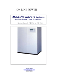
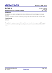
Rear Panel Controls & Functions
D
WARNING
5
4
3
2
8
7
6
1
2
3
4
CAUTION
4
9
3
8
2
7
UPS-10000
1
MODEM LINE
CAUTION MAXIMUM OF 4 BATTERY EXTENSION UNITS MAY BE USED.
FOR DISCONNECT USE ONLY. NOT INTENDED FOR CURRENT INTERRUPTION.
TURN OFF POWER SWITCH DURING BATTERY EXTENSION CONNECTION.
H
SERIAL NO.
MADE IN U.S.A.
WARNING
FOR CONTINUED PROTECTION
AGAINST FIRE, REPLACE ONLY
WITH WITH UL LISTED FUSE OF
SAME TYPE AND RATING.
BATTERY FUSE
E
US
EF
E F
FUS
FOR CONTINUED PROTECTION
AGAINST FIRE, REPLACE ONLY WITH
WITH UL LISTED FUSE OF SAME TYPE AND RATING.
WARNING
125V 10A
FUSE
B
C
FUS
E
US
30A
UNINTERRUPTIBLE
POWER SUPPLY
AC INPUT:
120V, 60HZ, 10A MAX, P.F.=1
UPS OUTPUT: 120V, 60HZ, 6.2A MAX, P.F.=1
DC IN/OUTPUT: 48V, 30A MAX
6
0
S
FU E
Leave at least 2" of ¨
clearance to ensure
proper air flow.
48VDC
TO: EXT-8000
A
U® L LISTED
27F2
ALARM
INTERFACE
5
1
B1B2B3B4
RISK OF ELECTRIC SHOCK
THIS UPS RECEIVES POWER
FROM MORE THAN ONE
SOURCE—DISCONNECTION
FROM THE AC SOURCE AND
THE DC SOURCE IS REQUIRED TO DEENERGIZE
THIS UNIT PRIOR TO
SERVICING.
HAZARDOUS LIVE PARTS
INSIDE THIS UPS ARE
ENERGIZED FROM THE
BATTERY SUPPLY EVEN
WHEN THE INPUT AC
POWER IS DISCONNECTED.
DO NOT REMOVE COVER.
NO USER SERVICEABLE
PARTS INSIDE.
REFER
SERVICING TO QUALIFIED
PERSONNEL.
G
REMOTE CONTROL
BAUD
RATE
1
ON
9
F
E
RS-232
INTERFACE
TO REDUCE THE RISK
OF ELECTRIC SHOCK,
INSTALL IN A TEMPERATURE
AND HUMIDITY CONTROLLED
INDOOR AREA FREE OF
CONDUCTIVE CONTAMINANTS.
U
P
S
O
U
T
P
U
AC FUSE
T
AC IN
J
I
A Ventilation Holes
Cooling fan will always be on during UPS operation.
B Battery Extension Fuse
30A fuse protects against short or overload in the EXT-8000 circuit.
If you are not sure how ¨
much power your
equipment draws, see
insert, “Load Ratings
for Typical Equipment”.
C UPS Output Sockets
Connect equipment to be backed up to these outlets. UPS-10000 has 4 sockets and
maximum output power of 750 watts. UPS-16000 has 6 sockets and maximum
output power of 1200 watts.
See p. 10 for more ¨
information about serial
communications.
D RS-232C Serial Port (only on UPS-10000S or UPS-16000S models)
For serial communication between UPS and an external device (e.g. a PC).
E Baud Rate Switch
Selects baud rate for the RS-232C serial port.
See p. 9 for more ¨
information about
Remote UPS Access.
F Remote Control Phone Connectors
Telephone equipment connectors for remote access. Connect incoming telephone
line to the LINE jack. Connect phone equipment to the MODEM jack.
See p. 8 for more ¨
information about
connecting your UPS to
a network.
G Alarm Interface Port
For communication between UPS and a file server. Requires monitoring software.
H Battery
Extension
Connector
(only
10000/16000)
Connects to the EXT-8000 Battery Extension Unit. 48Vdc/30A maximum.
I AC Fuse
Protects agains short or overload in the AC circuit.
J AC Power Cord
Plugs into the AC outlet.
Rear Panel Controls & Functions
3
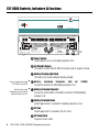
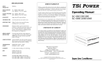
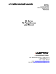
EXT-8000 Controls, Indicators & Functions
POWER
I N D I C ATO R
EXT-8000
ON
A
AC ON
BAT CHRG
B C
OFF
BATTERY EXTENSION UNIT
TO: UPS-10000/16000
OR EXT-8000
TO: EXT-8000
D
E
48VDC
BATTERY FUSE
F
FUS
REPLACE ONLY WITH UL LISTED
FUSE OF SAME TYPE AND RATING
• TURN OFF POWER SWITCH DURING EXT.
BATTERY CONNNECTION.
30A • FOR DISCONNECT USE ONLY. NOT INTENDED
250VAC
FOR CURRENT INTERRUPTION.
3A
AC FUSE
AC IN
E
US
EF
E F
E F
CAUTION
E
US
FUS
MADE IN U.S.A.
E
US
30A
FUSE
SERIAL NO.
• INTENDED FOR INSTALLATION IN A PROTECTED
ENVIRONMENT.
• HAZARDOUS VOLTAGE INSIDE.
• NO USER SERVICEABLE PARTS.
• DISCONNECT AC AND DC POWER BEFORE OPENING
THIS COVER.
• REFER SERVICING TO QUALIFIED PERSONNEL.
S
FU E
BATTERY
EXTENSION
120V, 60HZ, 3A MAX, P.F.=1
48V, 30A MAX
S
FU E
AC INPUT:
DC IN/OUTPUT:
FUS
CAUTION
EXT-8000
WARNING
FOR CONTINUED PROTECTION AGAINST FIRE,
REPLACE ONLY WITH SAME TYPE AND RATING OF FUSE.
G
H
A Power Switch
Use this switch to turn on the Battery Extension Unit.
B AC ON Light (Green)
This light is on when the EXT-8000 is turned on and AC power is normal.
C Battery Charging Light (Red)
This light turns on when batteries are being charged.
See p. 13 about connecting ¨
EXT-8000 to your UPS.
D Battery Extension Connector (Not for
Connects to another EXT-8000 Battery Extension Unit.
To find out how much ¨
holdup time you can expect,
consult the chart on p. 12.
E Battery Extension Connector
Connects to a UPS-10000, UPS-16000 or another EXT-8000 Battery
Extension Unit.
1000B)
F Battery Extension Fuses
protects against short or overload in the battery extension circuit.
G AC Fuse
Protects agains short or overload in the AC circuit.
H AC Power Cord
Plugs into the AC outlet.
4
UPS-10000, 16000 & EXT-8000 Operating Instructions
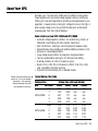
About Your UPS
Normally, your TSi Power UPS-10000 and UPS-16000 Uninterruptible
Power Supplies work as constant voltage regulators and line conditioners,
filtering out noise and irregularities to provide pure sinewave power to your
equipment. However, when incoming AC voltage is too low or too high, or
when a power outage occurs, they provide the same pure uninterrupted
sinewave power from their internal batteries.
Some Features of your UPS-10000 and UPS-16000
• Automatic voltage regulation, isolation, line conditioning, common &
differential noise filtering with ferro-resonant transformer.
• Zero transfer time—resulting in uninterrupted pure sinewave output.
• Extended backup time possible with additional Battery Extension Units.
• Brownout & overvoltage protection.
• 3-way voltage surge protection by heavy duty Surge Suppressors.
• Two-tone audible alarm warning for AC failure and low battery.
• Overload protection at 110% of maximum output.
• Novell, UNIX, VMS, OS/2, Windows 3.11/95/NT, Mac OS & other
LAN compatible UPS alarm reporting.
• Optional true RS-232 alarm port on selected models.
Please consult the backup time ¨
chart on p. 12 for more detailed
information. Just remember
that actual holdup times with
your equipment could vary.
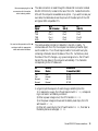
Typical Backup Time Table
Configuration
UPS
EXT-8000
none
1
UPS-10000
2
3
4
none
1
UPS-16000
2
3
4
Holdup Time with Load (hh:mm)
300W
0:25
1:33
2:47
4:06
5:28
0:35
1:37
2:46
3:57
5:12
600W 900W
0:11
n/a
0:42
n/a
1:17
n/a
1:54
n/a
2:33
n/a
0:18 0:11
0:51 0:33
1:28 0:56
2:06 1:21
2:46 1:47
1200W
n/a
n/a
n/a
n/a
n/a
0:08
0:23
0:39
0:57
1:16
About Your UPS
5
Operating Instructions
For the UPS-16000, a dedicated ¨
AC socket (no other equipment on
the same line) is recommended.
For a more complete and up-to- ¨
date guide to power requirements,
please check the accompanying
insert, “Load Ratings for Typical
Equipment”. Also, you can usually
find the power consumption printed
in the rear of the equipment.
1) Place the UPS near a grounded (3 pronged) AC outlet, rated at 120V,
60Hz, 15A. Plug the power cord of the UPS into the AC socket. Note that
the UPS will only start up when AC power is present. Therefore the UPS
should be left on at all times when uninterrupted power is required.
2) Make sure that the POWER switch is OFF. Verify that the MODE
switch is in the NORMAL position. Plug in the equipment to be backed up
into the outlets in the rear of the UPS. Turn the equipment off for now.
CAUTION: Make sure that your equipment does not draw more the
maximum power rating of the UPS. For the UPS-10000, the maximum
power rating is 750W. For the UPS-16000, the maximum power rating is
1200W.
• A PC draws between 150W and 250W (without the monitor).
• A 14" color monitor draws about 75W.
• A big screen monitor (17" & up) draws between 100W and 200W.
• A laser printer draws between 600W and 1000W.
CAUTION: A laser printer should not be backed up by your UPS unless
absolutely necessary. A laser printer draws high pulsed power that may
interfere with sensitive equipment.
3) Turn on the POWER switch. You should immediately hear the UPS
“humming” as it is energized. The following indicators should now turn on:
• AC ON green light.
• BAT CHRG red light should be on or flickering.
• OUTPUT VOLTAGE green bar-graph should show between 4 and
6 light segments turned on.
• BATTERY VOLTAGE red bar-graph should show between 4 and 9
light segments turned on.
CAUTION: It is recommended that ¨
you not exceed 90% of your UPS’s
maximum output (8 yellow light
segments). This reduces the
likelihood that your equipment will
accidentally trigger the overload
shutoff circuitry of the UPS.
6
4) About 5 seconds after turning on the POWER switch, your equipment
will be supplied with power. As you turn your equipment on one by one,
you should see the OUTPUT LOAD yellow bar-graph turn on, with
increasing number of lights. Verify that all your equipment is working
properly.
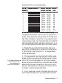
5) The LED bar-graph indicators give a quick and complete overview of
UPS-10000,1000B, 16000 & EXT-8000 Operating Instructions
the status of the UPS. They can be read as follows:
# OF ON BARGRAPH DISPLAY
SEGMENTS
1
2
3
4
5
6
7
8
9
10
OUTPUT
VOLTAGE
112 Vac
114 Vac
116 Vac
118 Vac
120 Vac
122 Vac
124 Vac
126 Vac
128 Vac
130 Vac
BATTERY OUTPUT
VOLTAGE LOAD
40.6 Vdc
11%
42.2 Vdc
22%
44.8 Vdc
33%
46.4 Vdc
44%
48.0 Vdc
55%
49.6 Vdc
66%
51.2 Vdc
77%
52.8 Vdc
88%
54.4 Vdc
99%
56.0 Vdc
110%
6) As a test of your UPS, you can simulate an AC power outage by
unplugging the UPS from the AC outlet. As soon as you unplug the UPS,
the green AC ON light should go off and the yellow INV ON light should
begin to blink, indicating an AC power failure. All your equipment should
continue operating normally. Also, if the ALARM switch is in the ENABLE
position, the audible alarm should “beep” about once every second. You can
turn off the alarm by placing the ALARM switch in the DISABLE position.
7) Plug the UPS’s power cord back into the AC outlet. After about 3
seconds, the AC ON light will turn on, the yellow INV ON light will turn
off, and the red BAT CHRG light will turn on. Your equipment should
continue operating normally.
The Low Battery Audible Alarm ¨
cannot be turned off. It will
sound regardless of the
position of the ALARM Switch.
8) If the power outage had been real and prolonged, the battery voltage
will drop until there is only a few minutes of battery power left (3 or fewer
red BATTERY VOLTAGE light segments on.) At this time, the audible
alarm will come on as a continuous tone (or if the ALARM switch had been
enabled, change from a beep once a second to a continuous tone.) At the
same time, a warning will be sent via the alarm ports in the rear of the UPS
to a file server or computer to prepare for shutdown.
9) If the AC power outage continues, and the battery drops below 42 Vdc,
the UPS will shutoff, and all power to your equipment will be turned off.
Operating Instructions
7
If the batteries are fully drained, ¨
it will take longer for the BAT
CHRG light to go off completely,
sometimes as long as 24 hours.
However, when it flickers, that
indicates that the batteries are
more than 90% charged.
10) When AC power returns, the UPS will restart automatically, restore
power to your equipment, and begin recharging the batteries. As the
batteries approach full charge, in about 4 to 6 hours, the red BAT CHRG
light will begin to flicker, and eventually turn off after several more hours.
11) In the event of an overload or short-circuit, the UPS will shut off
immediately. When this occurs, the overload or short-circuit must be
removed, and the POWER switch must be turned off, then on again, in
order to re-start the UPS.
Network Alarm Interface & Installation
Pin #
Name
Function
1
SHUTDOWN
Input to UPS. A positive pulse
5V or higher and lasting longer than 1/4
sec will shut down the UPS when it is
running on battery power.
6
ACFAIL (O-C)
Open-Collector Output from UPS.
Normally open, this transistor switch will
close when AC fails.
2
ACFAIL
Output from UPS. Normally low, this
signal will go high when AC fails.
7
BATLOW
Output from UPS. Normally low, this
signal will go high when about 2 minutes
of battery reserve power (at full load)
remains.
3
ACFAIL (O-C)
Open-Collector Output from UPS.
Normally closed, this transistor switch will
open when AC fails.
4
GND
Ground.
9
GND
Ground.
5 BATLOW (O-C) Open-Collector Output from UPS.
Normally open, this transistor switch will
close when about 2 minutes of battery
reserve power (at full load) remains.
9
UPS INTERNAL ALARM CIRCUIT
BAT NORMAL
BAT LOW
AC GOOD
AC FAIL
BAT NORMAL
BAT LOW
5
8
4
7
3
6
2
1
RS-232
RS-232
8
AC GOOD
AC FAIL
NORMAL
SHUTDOWN
Your UPS-10000 and UPS-16000 provide UPS alarm
reporting for Novell NetWare, UNIX, Windows for
Workgroups, Windows 95, Windows NT, Mac OS & other
file servers and workstations. See accompanying insert,
“Accessories and Software” for a full listing of currently
available UPS monitoring & shutdown software.
LAN connections are made through the ALARM port
located in the rear. You should follow the instructions in
your network or workstation documentation on attaching a
UPS. This ALARM port is a DB-9 female connector which
you can adapt for your own hardware and software to
monitor the UPS.
The diagram on the left shows the pin-outs of the alarm
interface port. Note that some older units may not be
equipped with all the functions shown. Please contact TSi
Power for more information.
If you wish to use the alarm interface port for custom
applications, take into consideration the following limitations.
• Pins 3, 5 & 6 are open-collector transistor outputs, limited
to switching 40V and sinking 20mA of current.
• Pins 2 and 7 are RS-232 compatible outputs. They will
switch from RS-232 low (about -10V) to high (about
+10V), and can drive a 25mA load.
UPS-10000, 16000 & EXT-8000 Operating Instructions
• A positive (> 5V) pulse lasting longer than 1/4 second at pin 1 is required
to shut down the UPS during power failures. This pin is inactive when the
AC mains is normal.
• For performance & safety, your alarm monitoring circuit should be
isolated (via transformers, relays or optocouplers) from the rest of your
network.
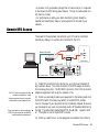
Remote UPS Access
The power to the equipment connected to your UPS can be controlled
remotely by dialing in to a phone line connected to the UPS.
Modem Data Cable
REMOTE CONTROL
Modem
MODEM
Phone Jack
LINE
Rear of UPS
WARNING
RS-232
INTERFACE
TO REDUCE THE RISK
OF ELECTRIC SHOCK,
INSTALL IN A TEMPERATURE
AND HUMIDITY CONTROLLED
INDOOR AREA FREE OF
CONDUCTIVE CONTAMINANTS.
5
4
3
2
8
7
REMOTE CONTROL
BAUD
RATE
1
6
1
2
3
4
4
9
3
8
2
7
27F2
UPS-10000
1
SERIAL NO.
MODEM LINE
MADE IN U.S.A.
CAUTION MAXIMUM OF 4 BATTERY EXTENSION UNITS MAY BE USED.
FOR DISCONNECT USE ONLY. NOT INTENDED FOR CURRENT INTERRUPTION.
TURN OFF POWER SWITCH DURING BATTERY EXTENSION CONNECTION.
WARNING
FOR CONTINUED PROTECTION
AGAINST FIRE, REPLACE ONLY
WITH WITH UL LISTED FUSE OF
SAME TYPE AND RATING.
BATTERY FUSE
E F
S
FU E
E
US
30A
UNINTERRUPTIBLE
POWER SUPPLY
AC INPUT:
120V, 60HZ, 10A MAX, P.F.=1
UPS OUTPUT: 120V, 60HZ, 6.2A MAX, P.F.=1
DC IN/OUTPUT: 48V, 30A MAX
6
0
B1B2B3B4
48VDC
TO: EXT-8000
LISTED
UL
®
ALARM
INTERFACE
5
1
ON
9
CAUTION
125V 10A
FUS
EF
E
US
FUSE
FUS
RISK OF ELECTRIC SHOCK
THIS UPS RECEIVES POWER
FROM MORE THAN ONE
SOURCE—DISCONNECTION
FROM THE AC SOURCE AND
THE DC SOURCE IS REQUIRED TO DEENERGIZE
THIS UNIT PRIOR TO
SERVICING.
HAZARDOUS LIVE PARTS
INSIDE THIS UPS ARE
ENERGIZED FROM THE
BATTERY SUPPLY EVEN
WHEN THE INPUT AC
POWER IS DISCONNECTED.
DO NOT REMOVE COVER.
NO USER SERVICEABLE
PARTS INSIDE.
REFER
SERVICING TO QUALIFIED
PERSONNEL.
FOR CONTINUED PROTECTION
AGAINST FIRE, REPLACE ONLY WITH
WITH UL LISTED FUSE OF SAME TYPE AND RATING.
WARNING
U
P
S
O
U
T
P
U
T
AC FUSE
AC IN
PC Power Cable
The UPS will not interfere with the ¨
modem or telephone—it will
however protect them from surges
and spikes on the telephone line.
It may take about a minute after the ¨
UPS is turned on before the MODE
switch becomes operational.
(1) Make the connections to the phone line, your phone and modem (if
any) as shown above. The LINE connector of the UPS always connects to
the incoming phone line. The MODEM connector of the UPS connects to
telephone equipment such as phone, modem or fax.
(2) When you are ready to place your equipment in the remote mode, turn
the MODE switch (the rotary key switch) to the REMOTE position.
Caution: the power to your equipment will be immediately removed. Make sure
you have saved all your work and were ready to shut off the system before taking
this step. The amber light marked REMOTE should flash. Leave the UPS
on. The system is now in the REMOTE mode.
(3) When you want to turn on the equipment connected to the UPS at a
Remote UPS Access
9
later time from another location, simply dial the number of the phone line
to which the UPS is connected. After 3 to 5 rings, the UPS will detect the
ringing and supply power to the equipment. Also, if the phone line
becomes busy—e.g. when a modem establishes connection—the UPS will
continue to supply the equipment with power.
(4) When you hang up the phone, the UPS will remove power to the
equipment after 30 to 40 seconds. You can redial the number and keep the
equipment on within this time.
For example, suppose you wished to access a remote PC from your home.
Normally, you would have to keep your remote PC turned on all the time,
thus reducing its life and wasting electricity. With your TSi Power UPS, you
can keep the remote PC off, and only turn it on when necessary. You would
configure the remote PC to run a communications program—such as
pcAnywhere or Carbon Copy—upon boot-up, and then place the UPS in
the REMOTE mode, turning the remote PC off. At home, when you need
to access the remote PC, you would dial the UPS, turn on the remote PC,
and let your home modem and remote modem establish a connection.
When finished, you can hang up, and power to the PC will be turned off
automatically after 30 to 40 seconds. This process can be repeated as many
times as necessary.
Many other applications are possible, to make the UPS an integral part of
your computer system.
Serial RS-232 Communications (UPS-10000S & UPS-16000S only)
In the models equipped with the “S”-option, there is an additional way to
communicate between the computer and the UPS. Using the RS-232
protocol for serial communications, these models can exchange information
via the serial port, at rates of 1200, 2400, 4800 or 9600 baud. The baud
rate is set by the DIP switches
marked BAUD RATE, next to
1200 baud
2400 baud
4800 baud
9600 baud
the serial connector, as shown.
ON
ON
1
1 0 UPS-10000,1000B, 16000 & EXT-8000 Operating Instructions
2
3
4
ON
1
2
3
4
ON
1
2
3
4
1
2
3
4
See accompanying list of ¨
accessories for information
about ordering cables.
You can test the operation of the ¨
serial port with the appropriate
cable and modem software.
The cable connection is made through the female DB-9 connector marked
RS-232 INTERFACE, located in the rear of the UPS. Cables that link the
UPS with the computer are available as an option. If you wish to make your
own cable, the table below shows the pinouts of the serial ports of the UPS
and typical IBM compatible PC’s.
RS-232
Signal
UPS
(DB-9 female)
PC
(DB-9)
PC
(DB-25)
RXD
TXD
TDR
GND
Pin 3
Pin 2
Pin 4
Pin 5
Pin 2
Pin 3
Pin 4
Pin 5
Pin 3
Pin 2
Pin 20
Pin 5
The communications format is: 8 data bits, 1 stop bit, no parity. To
communicate with the UPS, the computer can send any character (byte)
over the serial line. The UPS will respond within 50 ms with two bytes,
containing information about the status of the UPS. Furthermore, when
the status of the UPS changes—e.g. a power outage occurs—the UPS will
transmit the new status to the computer automatically. The characters
corresponding to the UPS status are:
AC
Status
Battery
Status
Characters
Transmitted (HEX)
Fail
Fail
Normal
Normal
Low
Normal
Low
Normal
0C 0D
0D 0D
0E 0D
0F 0D
In a typical cycle the sequence of events may go something like this:
1) In response to a query, the UPS will respond with 0F 0D, corresponding to normal AC and battery conditions.
2) When a power outage occurs, the UPS transmits 0D 0D.
3) As the power outage continues and the battery level drops, the UPS
will transmit 0C 0D.
4) When AC power returns, the UPS will transmit 0E 0D, then later as
the battery becomes recharged, 0F 0D.
Serial RS-232 Communications 11
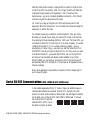
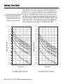
Backup Time Chart
If you are not sure how much power ¨
your equipment draws, check the rear
panel for input power ratings. You
can also consult the insert, “Load
Ratings for Typical Equipment”.
Some applications may require longer backup times than available with a
standalone UPS. An easy and cost effective way to extend backup time is
through TSi ’s EXT-8000 Battery Extension Units. Connecting just one
EXT-8000 to an UPS-16000 will increase total backup time to about 23
minutes at full load. Additional EXT-8000’s can be daisy-chained for even
longer backup times. The chart below shows backup times possible with
various combinations of UPS-10000, UPS-16000 and EXT-8000.
1.5 days
1.5 days
1 day
1 day
18 hrs
18 hrs
12 hrs
10 hrs
8 hrs
12 hrs
10 hrs
8 hrs
6 hrs
5 hrs
4 hrs
UP
S1
UP 000
0w
S10
00 ith 4
EXT
0w
UP
-80
ith
S00
10
3E
00
X
T
-80
0w
00
ith
2E
UP
XTS80
10
00
00
0w
ith
1E
XT80
00
3 hrs
2 hrs
90 min
1 hr
45 min
Typical Holdup Time
Typical Holdup Time
6 hrs
5 hrs
4 hrs
2 hrs
90 min
1 hr
45 min
30 min
30 min
20 min
20 min
15 min
UP
S
10 min
8 min
0
150
300
450
UP
S1
UP 600
0w
S16
00 ith 4
UP
0w
E
Sith XT-80
16
00
3E
00
XT0w
80
00
ith
UP
2E
SXT-8
16
000
00
0w
ith
1E
XT80
00
3 hrs
15 min
-10
00
0
600
UP
S-1
60
00
10 min
8 min
750
Load in W
UPS-10000 Holdup Time Chart
12 UPS-10000, 16000 & EXT-8000 Operating Instructions
0
200
400
600
800
1000
Load in W
UPS-16000 Holdup Time Chart
1200
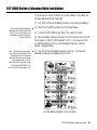
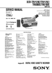
EXT-8000 Battery Extension Units Installation
To connect one or more EXT-8000’s to an UPS-10000 or UPS-16000, see
the figure below and follow these steps.
(1) Turn off the UPS and the Battery Extension Units before proceeding!
(3) Connect the EXT-8000(’s) and the UPS to a wall AC socket.
(4) Take the battery extension connector from the UPS and connect it with
the connector on the EXT-8000 marked TO UPS. If you have more than
one Battery Extension Unit, they would be daisy-chained in a similiar
manner. See figure below.
(5) Turn the UPS and the Battery Extension Units on. You have just
extended the backup time capability of your UPS.
WARNING
RS-232
INTERFACE
TO REDUCE THE RISK
OF ELECTRIC SHOCK,
INSTALL IN A TEMPERATURE
AND HUMIDITY CONTROLLED
INDOOR AREA FREE OF
CONDUCTIVE CONTAMINANTS.
5
4
3
2
REMOTE CONTROL
BAUD
RATE
1
8
7
6
1
2
3
4
LISTED
UL
®
27F2
ALARM
INTERFACE
5
1
ON
9
4
9
3
8
2
7
UPS-10000
1
SERIAL NO.
MODEM LINE
MADE IN U.S.A.
CAUTION MAXIMUM OF 4 BATTERY EXTENSION UNITS MAY BE USED.
FOR DISCONNECT USE ONLY. NOT INTENDED FOR CURRENT INTERRUPTION.
TURN OFF POWER SWITCH DURING BATTERY EXTENSION CONNECTION.
48VDC
TO: EXT-8000
WARNING
FOR CONTINUED PROTECTION
AGAINST FIRE, REPLACE ONLY
WITH WITH UL LISTED FUSE OF
SAME TYPE AND RATING.
BATTERY FUSE
E F
E
US
30A
UNINTERRUPTIBLE
POWER SUPPLY
AC INPUT:
120V, 60HZ, 10A MAX, P.F.=1
UPS OUTPUT: 120V, 60HZ, 6.2A MAX, P.F.=1
DC IN/OUTPUT: 48V, 30A MAX
6
0
B1B2B3B4
CAUTION
RISK OF ELECTRIC SHOCK
THIS UPS RECEIVES POWER
FROM MORE THAN ONE
SOURCE—DISCONNECTION
FROM THE AC SOURCE AND
THE DC SOURCE IS REQUIRED TO DEENERGIZE
THIS UNIT PRIOR TO
SERVICING.
HAZARDOUS LIVE PARTS
INSIDE THIS UPS ARE
ENERGIZED FROM THE
BATTERY SUPPLY EVEN
WHEN THE INPUT AC
POWER IS DISCONNECTED.
DO NOT REMOVE COVER.
NO USER SERVICEABLE
PARTS INSIDE.
REFER
SERVICING TO QUALIFIED
PERSONNEL.
S
FU E
125V 10A
FUS
EF
E
US
FUSE
FOR CONTINUED PROTECTION
AGAINST FIRE, REPLACE ONLY WITH
WITH UL LISTED FUSE OF SAME TYPE AND RATING.
WARNING
U
P
S
O
U
T
P
U
T
AC FUSE
AC IN
AC FUSE
AC IN
TO: UPS-10000/16000
OR EXT-8000
TO: EXT-8000
48VDC
BATTERY FUSE
CAUTION
• TURN OFF POWER SWITCH DURING EXT.
BATTERY CONNNECTION.
30A • FOR DISCONNECT USE ONLY. NOT INTENDED
250VAC
FOR CURRENT INTERRUPTION.
3A
E
US
EF
E
US
E F
E F
E
US
30A
FUSE
FUS
• INTENDED FOR INSTALLATION IN A PROTECTED
ENVIRONMENT.
• HAZARDOUS VOLTAGE INSIDE.
• NO USER SERVICEABLE PARTS.
• DISCONNECT AC AND DC POWER BEFORE OPENING
THIS COVER.
• REFER SERVICING TO QUALIFIED PERSONNEL.
S
FU E
MADE IN U.S.A.
S
FU E
BATTERY
EXTENSION
120V, 60HZ, 3A MAX, P.F.=1
48V, 30A MAX
SERIAL NO.
FUS
CAUTION
EXT-8000
AC INPUT:
DC IN/OUTPUT:
FUS
WARNING
REPLACE ONLY WITH UL LISTED
FUSE OF SAME TYPE AND RATING
FOR CONTINUED PROTECTION AGAINST FIRE,
REPLACE ONLY WITH SAME TYPE AND RATING OF FUSE.
TO: UPS-10000/16000
OR EXT-8000
TO: EXT-8000
48VDC
BATTERY FUSE
CAUTION
• TURN OFF POWER SWITCH DURING EXT.
BATTERY CONNNECTION.
30A • FOR DISCONNECT USE ONLY. NOT INTENDED
250VAC
FOR CURRENT INTERRUPTION.
3A
AC FUSE
AC IN
E
US
EF
E
US
E F
E F
E
US
30A
FUSE
• INTENDED FOR INSTALLATION IN A PROTECTED
ENVIRONMENT.
• HAZARDOUS VOLTAGE INSIDE.
• NO USER SERVICEABLE PARTS.
• DISCONNECT AC AND DC POWER BEFORE OPENING
THIS COVER.
• REFER SERVICING TO QUALIFIED PERSONNEL.
FUS
BATTERY
EXTENSION
120V, 60HZ, 3A MAX, P.F.=1
48V, 30A MAX
SERIAL NO.
MADE IN U.S.A.
S
FU E
AC INPUT:
DC IN/OUTPUT:
S
FU E
EXT-8000
FUS
CAUTION
FUS
WARNING
REPLACE ONLY WITH UL LISTED
FUSE OF SAME TYPE AND RATING
FOR CONTINUED PROTECTION AGAINST FIRE,
REPLACE ONLY WITH SAME TYPE AND RATING OF FUSE.
TO: UPS-10000/16000
OR EXT-8000
TO: EXT-8000
48VDC
BATTERY FUSE
CAUTION
• TURN OFF POWER SWITCH DURING EXT.
BATTERY CONNNECTION.
30A • FOR DISCONNECT USE ONLY. NOT INTENDED
250VAC
FOR CURRENT INTERRUPTION.
3A
AC FUSE
AC IN
E
US
EF
E
US
E F
E F
E
US
30A
FUSE
FUS
• INTENDED FOR INSTALLATION IN A PROTECTED
ENVIRONMENT.
• HAZARDOUS VOLTAGE INSIDE.
• NO USER SERVICEABLE PARTS.
• DISCONNECT AC AND DC POWER BEFORE OPENING
THIS COVER.
• REFER SERVICING TO QUALIFIED PERSONNEL.
S
FU E
MADE IN U.S.A.
S
FU E
BATTERY
EXTENSION
120V, 60HZ, 3A MAX, P.F.=1
48V, 30A MAX
SERIAL NO.
FUS
CAUTION
EXT-8000
AC INPUT:
DC IN/OUTPUT:
FUS
WARNING
REPLACE ONLY WITH UL LISTED
FUSE OF SAME TYPE AND RATING
FOR CONTINUED PROTECTION AGAINST FIRE,
REPLACE ONLY WITH SAME TYPE AND RATING OF FUSE.
TO: UPS-10000/16000
OR EXT-8000
TO: EXT-8000
48VDC
BATTERY FUSE
CAUTION
E
US
• TURN OFF POWER SWITCH DURING EXT.
BATTERY CONNNECTION.
30A • FOR DISCONNECT USE ONLY. NOT INTENDED
250VAC
FOR CURRENT INTERRUPTION.
3A
AC FUSE
AC IN
E
US
EF
E
US
30A
E F
• INTENDED FOR INSTALLATION IN A PROTECTED
ENVIRONMENT.
• HAZARDOUS VOLTAGE INSIDE.
• NO USER SERVICEABLE PARTS.
• DISCONNECT AC AND DC POWER BEFORE OPENING
THIS COVER.
• REFER SERVICING TO QUALIFIED PERSONNEL.
E F
BATTERY
EXTENSION
120V, 60HZ, 3A MAX, P.F.=1
48V, 30A MAX
FUS
MADE IN U.S.A.
FUSE
SERIAL NO.
S
FU E
AC INPUT:
DC IN/OUTPUT:
S
FU E
EXT-8000
FUS
CAUTION
FUS
Note: The maximum load rating of ¨
your UPS has not increased—only
the length of time it can back up
that load. So you cannot hook up
more equipment to your UPS,
above the maximum power rating,
just by adding EXT-8000’s. For
that, you need to use a larger UPS.
(2) Stack the EXT-8000(’s) under the UPS as shown below.
FUS
If you need to place the Battery ¨
Extension Units further away from
the UPS, you can purchase a 6 ft
long battery extension cable (TSi
Part # CA-8000A).
WARNING
REPLACE ONLY WITH UL LISTED
FUSE OF SAME TYPE AND RATING
FOR CONTINUED PROTECTION AGAINST FIRE,
REPLACE ONLY WITH SAME TYPE AND RATING OF FUSE.
UPS and Battery Extension Unit Connection
EXT-8000 Battery Extension Units 13
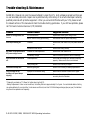
Trouble-shooting & Maintenance
WARNING: Please do not open the case and attempt to repair the UPS. High voltages are present and there are
no user servicable parts inside. Repairs can be performed only at the factory or at an authorized repair centers by
qualified personnel with protective equipment. When you encounter difficulties with your UPS, please consult
the relevant sections of this manual and check the trouble-shooting guide below. If you still have problems, please
call TSi Power’s Customer Service at (770) 263-6063.
Problem
Possible Causes
Suggested Solutions
Green AC ON light does not
turn on.
AC fuse has blown.
Replace with same type & rating of fuse.
Bad AC outlet or faulty ground wiring
Use another outlet or repair faulty wiring.
UPS keeps shutting off.
Overload.
Reduce load, then reset UPS (turn power switch off/
on.
Excessive inrush current.
Reduce load during startup.
No power to equipment when
AC power outage occurs.
Overload or Overtemperature.
Reduce load, then restart UPS.
Low Battery Voltage.
Wait for normal AC power to return to recharge.
UPS becomes hot and shuts
off.
Overtemperature.
Check that the cooling fan in the rear is working
properly. Make sure air flow is not blocked.
Faulty cooling fan.
Return UPS to factory for repair.*
†
Insufficient holdup time.
Batteries getting old.
Return UPS to factory for battery replacement.*
Circuit breaker in the
building’s AC panel keeps
tripping.
Improper circuit breaker rating.
Make sure the breaker is rated 20A or higher.
Overload.
Remove other equipment from the same circuit
served by the circuit breaker.
* Please call your dealer or TSi Power for before returning the UPS.
†
Battery Replacement: Under normal conditions, the battery lifetime is approximately 4 to 5 years. Your authorized dealer or factory
can replace batteries for a nominal fee. Under severe conditions (more than 150 full discharge-recharge cycles per year), the batteries
may have to be replaced more frequently.
1 4 UPS-10000,1000B, 16000 & EXT-8000 Operating Instructions
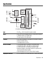
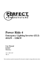
{
{
Ferro-Resonant
Transformer
Hot
Ground
Neutral
AC
Filtering
&
Protection
Solid-State
Relay
Resonant
Capacitor
+48VDC
Hot
Fuse
Inverter
Battery
Logic Ground
Neutral
}
UPS OUTPUT
To EXT-8000
AC INPUT
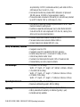
Specifications
Ground
Battery
Charger
UPS-10000 & UPS-16000 Block Diagram
Input
• 95~135VRMS, 60±3Hz, sinusoidal or pseudo-sinusoidal.
Output
• 120VRMS±5%, 60±1Hz sinewave, less than 5% total harmonic distortion.
• 1,200 watt maximum (UPS-16000 series).
• 750 watt maximum (UPS-10000 series).
Transfers
• Zero transfer time between AC and battery (no interruption of power).
• Brownout threshold: 95±2VRMS.
• Overvoltage threshold: 135±2VRMS.
Battery & Charger
•
•
•
•
Surge/Spike Protection
• AC hot to neutral, AC hot to earth ground & AC neutral to earth ground
UPS-10000 series: 48Vdc, 7Ah battery, 1.5A half-wave charger.
UPS-16000 series: 48Vdc, 10Ah battery, 2A half-wave charger.
EXT-8000 series: 48Vdc, 17Ah battery, 2A half-wave charger.
Batteries are charged to a float voltage of 56Vdc at an optimum rate to
ensure long life and maximum capacity.
• Typical recharging time is 4 hours to return to 90% of capacity.
Specifications 15
are protected by 3 MOV’s (metal oxide varistors), each rated at 150V &
6,500 amps of shunt current (8 × 20µs).
• Ferroresonant transformer provides 2000:1 attenuation of spikes and
200,000 joules & 100,000A of surge suppression capacity.
• Phone and modem connected to the dual RJ-11 connectors are protected
by an MOV rated at 150V & 2,500 amps (8 × 20µs).
Isolation
• Ferroresonant transformer provides complete isolation from AC mains.
Neutral is bonded to earth ground.
• Qualifies as a separately derived power source under National Electric
Code Article 250-5D and complies with FIPS Pub. 94, Isolating Transformer and Grounding Recommendations.
Noise Filtering
• Common mode noise is reduced ≥120dB at 20MHz.
• Transverse mode noise is reduced ≥50dB at 20MHz.
• All-steel chassis blocks radiated EMI/RFI noise.
Safety and Reliability Features
•
•
•
•
•
•
Designed to meet UL1778
Designed to meet FCC standards for EMI/RFI emissions.
External fuses protect all AC circuits and DC battery circuits.
Internal fuse protects inverter circuit.
Overload circuit disconnects the load at 110% of maximum load.
Polarized battery connector prevents accidents.
Size and Weight
• UPS-16000: 111 lbs (50kg).
Width - 17"; Depth - 21"; Height - 6.5" (432mm x 533mm x 165mm).
• UPS-10000: 80 lbs (36kg).
Width - 17"; Depth - 21"; Height - 5" (432mm x 533mm x 127mm).
• EXT-8000: 70 lbs (32kg).
Width - 17"; Depth - 21"; Height - 5" (432mm x 533mm x 127mm).
Operating Environment
• Humidity: 0 to 95%, non-condensing.
• Maximum withstanding weight: 400 lbs (180kg).
Warranty
• 2 years limited warranty, parts & labor (except for batteries).
• Battery manufacturer’s warranty on batteries (typically 1 year).
• Extended warranty available.
1 6 UPS-10000,1000B, 16000 & EXT-8000 Operating Instructions
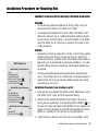
Installation Procedure for Mounting Kits
ASSEMBLY & INSTALLATION OF MK-8000A, MK-8000B & MK-8000D
WARNING
• Do not place any equipment heavier than 30 lbs (14 kg) on top of a
rack-mounted UPS-10000, UPS-16000 or EXT-8000.
• It is strongly recommended that the UPS-10000, UPS-16000 or EXT8000 unit is placed on top of a weight-bearing shelf capable of supporting a minimum of 200 lbs (90 kg). Use the MK-8000A or MK-8000B
(with MK-8000D for 24" racks) only to prevent front-to-back or sideto-side movements.
Kit Parts List
MK-8000A (Front Brackets)
Item
Qty
MK-8000A Left
1
MK-8000A Right
1
#8-32 x 5/16" Screw A
4
G-shaped #10-32 Clip Nut
4
#10-32 x 3/8" Bolt B
4
MK-8000B (Rear Brackets)
Item
Qty
MK-8000B Left
1
MK-8000B Right
1
#8-32 x 5/16" Screw A
4
G-shaped #10-32 Clip Nut
4
#10-32 x 3/8" Bolt B
4
MK-8000D (24" Rack Adaptor)
Item
Qty
MK-8000D
1
#10-32 x 3/8" Bolt B
2
CAUTION
• Because the units are very heavy (80 to 130 lbs, or 36 to 60 kg), exercise
extreme caution when lifting or turning over the units. Never try to
handle the unit alone. Hydraulic jack or other safe and secure means of
keeping the unit in placd should be used during installation. For a safe
and secure lifting, moving or positioning, 4 strong adult assistants may
be required.
• Use heavy duty leather gloves and steel-toed shoes to avoid personal
injury. Do not drop the unit on a hard surface. A well-built wooden or
metal stretcher with 4 long and sturdy handles may help with moving
and positioning of the unit.
Installation Procedure (see drawing on p.18):
1. Make sure that you have both MK-8000A and MK-8000B (and 2 sets of
MK-8000D for 24" racks), and that no parts are missing.
2. Attach the front brackets (MK-8000A left and right) to the unit by
turning the unit upside down, then tightening with the #8 bolts A . If
the rack is 24" wide, then fasten the MK-8000D 24" rack adaptors (not
shown) to the front brackets using the #10 bolts provided with the MK8000D kit. Carefully turn the unit over to its upright position.
3. Inspect the rack or cabinet in which the unit is to be installed. Verify
Installation Procedures for Mounting Kits 17
that both the front and rear mounting rails are installed. The distance
between the front and rear rails should be between
23.5" and 26" (60cm ~ 66cm). Place the 8 clip
nuts (not shown, 2 in each rail) at the
B
desired height. The two clip nuts in each
rail should be separated by 1.75"
(44mm). Verify that the clip nuts
of the four rails are at equal
MK-8000B
Right Bracket
heights from the floor.
B
MK-8000B
Left Bracket
MK-8000A
Left Bracket
A
1-3/4"
(44mm)
B
A
4. Mount the rear brackets
MK-8000B Left and Right to
B
the rear mounting rails by
A
A
00
80
KM
tightening B into the 4 clip
ket
Right Brac
nuts already in position. If the
rack is 24" wide, fasten the MK8000D 24" rack adaptors first to the rear brackets.
A
1-3/4"
(44mm)
5. With the help of your assistants, place the unit on top of a metal or
wooden stretcher. Then lift, carry and position the unit inside the rack.
Carefully slide the unit into the rack or cabinet. The rear of the unit
(without the brackets) must enter the cabinet first, from the front of the
cabinet.
6. While the unit is being held at the desired location and height by your
assistants, you should secure the unit firmly to the cabinet by fastening
the front mounting brackets of the unit into the front rails using B
and 4 clip nuts already in place.
7. While the unit is still being held at the desired location and height, the
rear brackets should be fastened to the unit (from the bottom of the
unit) with A .
8. When the unit is being held firmly in position by the 4 brackets at all 4
corners by all 16 bolts (4 in front, 8 from bottom, 4 in rear), and all the
bolts are tightly fastened, the stretcher may be removed from under the
unit.
18 UPS-10000, 16000 & EXT-8000 Operating Instructions
Limited Warranty
TSi Power warrants this product to be free from defects in
materials and workmanship for two (2) years† from the date of
purchase from TSi Power or its authorized representatives. TSi
Power will repair (or at its option, replace) any defective
component(s) during this warranty period.
To make a request or claim for service under this limited
warranty, the original purchaser must return the product, in the
original shipping container or equivalent, to TSi Power or its
authorized distributor, accompanied by a written receipt showing the date of purchase, dealer’s name, and both the model name
and serial number of the product.
Warranty does not cover transportation costs. Damage by
misuse, accident or unauthorized tampering of the product is not
covered by the warranty. NO OTHER WARRANTIES ARE
EXPRESSED OR IMPLIED. TSI POWER CORP. IS NOT
LIABLE FOR CONSEQUENTIAL DAMAGES. THIS WARRANTY GIVES YOU SPECIFIC LEGAL RIGHTS, AND
YOU MAY ALSO HAVE OTHER RIGHTS WHICH VARY
FROM STATE TO STATE.
†
Excluding batteries. Battery manufacturer’s warranty applies on
batteries.
Limitation of Liability
IN NO EVENT SHALL TSI POWER OR ITS SUPPLIERS BE
LIABLE FOR ANY DAMAGES WHATSOEVER (INCLUDING WITHOUT LIMITATION, DAMAGES FOR LOSS OF
BUSINESS PROFITS, BUSINESS INTERRUPTION, LOSS
OF BUSINESS INFORMATION, OR OTHER PECUNIARY
LOSS) ARISING OUT OF THE USE OR INABILITY TO
USE THIS TSI POWER PRODUCT, EVEN IF TSI POWER
HAS BEEN ADVISED OF THE POSSIBILITY OF SUCH
DAMAGES. SOME STATES DO NOT ALLOW THE LIMITATION OR EXCLUSION OF LIABILITY FOR INCIDENTAL OR CONSEQUENTIAL DAMAGES, SO THE ABOVE
LIMITATIONS MAY NOT APPLY TO YOU.
TSi POWER CORPORATION
1103 West Pierce Avenue
Antigo, WI 30071, USA
Phone: (715) 623-0636 FAX: (715) 623-2426
Internet: www.tsipower.com
e-mail: [email protected]
© Copyright—2002 TSi Power Corp. All rights reserved.
TSi Power’s ongoing product improvement process makes specifications subject to change.
Other company’s product names herein are for identification purposes only and may be trademarks of their respective companies.