1
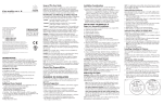
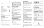
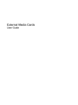
Scope of This User Guide
COLORCAST 14 CONDUIT
i n s t a l l a t i o n
®
g u i d e
The goal of this user guide is to explain in easily understandable
language the necessary steps to install ColorCast 14 Conduit and assure
peak performance. Its intended use is for reference only, by persons who
are fully qualified. This document should never be considered a substitute
for any provision of a regulation or state and/or local code.
Identification and Warnings of Safety Hazards
Color Kinetics Incorporated
10 Milk Street, suite 1100
Boston, MA 02108
Tel 888 Full RGB
Tel 617 423 9999
Fax 617 423 9998
[email protected]
www.colorkinetics.com
ColorCast 14 Conduit
ITEM# 123-000008-00 (Fixture, White)
123-000008-01 (Fixture, Black)
ITEM# 123-000003-00 (Base, White)
123-000003-01 (Base, Black)
This product is protected by one or more of the following patents: U.S. Patent Nos.
6,016,038, 6,150,774 and other patents listed at http://colorkinetics.com/patents/.
Other patents pending.
©2005-2006 Color Kinetics Incorporated. All rights reserved. Chromacore, Chromasic,
Color Kinetics, the Color Kinetics logo, ColorBlast, ColorBlaze, ColorBurst, ColorCast,
ColorPlay, ColorScape, Direct Light, iColor, iColor Cove, iPlayer, Optibin, Powercore,
QuickPlay, Sauce, the Sauce logo, and Smartjuice are registered trademarks and
DIMand, EssentialWhite, eW, IntelliWhite, iW, and Light Without Limits are trademarks
of Color Kinetics Incorporated.
All other brand or product names are trademarks or registered trademarks of their
respective owners.
PUB-000135-00 Rev 01
Specifications subject to change without notice.
Getting Started
Color Kinetics® ColorCast™ 14 Conduit offers indoor/outdoor wall
washing, up to 15 feet, and large alcove lighting in a conduit ready,
compact linear housing. Its power-on-board technology makes it easy
to install.
This guide contains important information on planning, installing, and
operating your new ColorCast 14 Conduit. For your protection, read it
carefully and save it for future reference.
Included in this box
• 1 ColorCast 14 Conduit fixture
• Installation Guide
• Warranty and Registration cards
Additional items needed
•
•
•
•
•
•
olorCast 14 Conduit Base (ITEM# 123-000003C
Color Kinetics Data Enabler (ITEM# 106-000003-04/05)
12 AWG, 4 conductor, copper wire
#10 mounting screws (M5) and tools
3/4" NPT conduit and hubs as required
5/16" hex wrench or adjustable wrench for seal plugs (shipped
with base)
Optional items
• 3/16" OD braided safety cable and hardware as required.
In accordance with ANSI Z535.4-2002 the following system of
identifying the severity of the hazards associated with the products is
used:
“danger” Imminently hazardous situation which, if not avoided, will
result in death or serious injury.
“warning”Potentially hazardous situation that, if not avoided, could
result in death or serious injury.
“caution” Potentially hazardous situation that, if not avoided, may
result in minor or moderate injury or property damage.
danger: Ensure that main power supply is off before installation or
wiring, ColorCast 14 Conduit. Failure to adhere to these instructions
will result in death or serious injury.
danger: ColorCast 14 Conduit must be installed by a qualified
electrician in accordance with NEC and relevant local codes. Failure
to comply will result in death, serious injury, or property damage.
warning: Do not attempt to install or use ColorCast 14 Conduit
until you read and understand the installation instructions, and safety
labels. Failure to adhere to these instructions could result in serious
injury or property damage.
warning: Do not use ColorCast 14 Conduit if the lens, housing, or
power cables are damaged. Doing so can result in death, serious
injury, and property damage.
warning: As dictated by a Structural Engineer and/or local code,
install safety cables to ColorCast 14 Conduit fixtures. Failure to do so
can result in injuries or property damage.
warning: When using safety cables, ensure that they comply to the
specifications given in this user guide. Failure to comply can result in
injuries or property damage.
warning: ColorCast 14 Conduit has line voltage risk of shock and
no user serviceable parts. Do not attempt to open the fixture. Doing so
can result in death, serious injury, and property damage.
caution: Use appropriate materials and mounting methods to support
the fixture adequately. Failure to do so can result in property damage
and void the warranty
caution: Do not exceed the specified voltage and current input.
Doing so will result in property damage and void the warranty.
caution: Do not exceed the maximum number of specified fixtures in
a light run. Doing so will result in current overload.
caution: Do not use sharp tools near or on the fixture lens. Doing so
will result in property damage and void the warranty.
caution: Do not hot swap. Ensure that power to the fixture is off
before connecting or disconnecting fixtures. Hot swapping will result
in property damage and void the warranty.
caution: ColorCast 14 Conduit is a Class 2 LED product with
LED radiation. Do not stare into beam or view directly with optical
instruments.
note: The instructions and precautions set forth in this user guide
are not necessarily all-inclusive, all conceivable, or relevant to all
applications as Color Kinetics cannot anticipate all conceivable or
unique situations.
owner/user responsibilities
It is the responsibility of the contractor, installer, purchaser, owner, and
user to install, maintain, and operate ColorCast 14 Conduit in such a
manner as to comply with all state and local laws, ordinances, regulations, and the American National Standard Institute Safety Code.
plan the installation
The nature and complexity of ColorCast 14 Conduit installation
requires in-depth planning to ensure timely, successful installation with
minimal complications and down time.
planning suggestions
When planning ColorCast 14 Conduit installation, Color Kinetics
suggests doing the following:
• Consult an Electrical Inspector to approve all wiring plans.
• Refer to local and state codes for installation compliance.
• Create a Layout Plan drawing.
• Create a Mapping Grid. Use this grid to record serial numbers for
easy reference and addressing.
• Employ Color Kinetics Application Engineering Services.
installation considerations
When creating your installation plan, consider the following:
• Location of Data Enabler in relationship to lights. Each Data Enabler
can support up to 38 (120VAC), 58 (220VAC), or 61 (240VAC)
ColorCast 14 fixtures, using a 50-foot, field-cuttable leader cable.
The Data Enabler supports a slightly greater or fewer number of
fixtures depending on customized installation parameters.
note: By decreasing the length of the leader cable you can increase
the number of ColorCast 14 fixtures per run. For more information
contact Color Kinetics or refer to the Configuration Calculator
located at www.colorkinetics.com/support.
• Calculate the number of fixtures per Data Enabler. Use the
Configuration Calculator located at www.colorkinetics.com/support
to calculate the number of fixtures you can put on a data enabler.
The fixtures to Data Enabler ratio is determined by the parameters
of your installation. Installation parameters include all or part of the
following: line voltage, fixture type, leader length, jumper lengths,
and wire gauge.
• Location of the fixture and method of attaching. Mounting hardware
is dictated by the mounting surface. Ensure that the hardware used
is appropriate for the mounting surface.
• Spacing between fixtures determines the number of fixtures per run.
For the maximum number of ColorCast 14 Conduit fixtures per run,
install fixtures butted end-to-end. You can also install the fixtures
spaced apart. Increasing the space between fixtures decreases the
number of fixtures per run.
• Install and wire the Data Enabler after installing ColorCast 14
Conduit fixtures. Refer to the Data Enabler Installation Guide.
STEPS TO A SUCCESSFUL INSTALLATION
1. Record serial numbers and identify fixtures as you unpack them.
Note the installation location on a mapping grid.
2. Install fixtures.
3. Address the fixtures.
4. Install the Data Enablers.
5. Connect power and data from the Data Enabler to the fixtures.
record serial numbers
1. As you unpack the fixtures record the serial numbers.
Each ColorCast 14 Conduit fixture has a unique serial number
programmed at the time of manufacture.
2. Write the serial numbers onto a Mapping Grid.
3. Using the Layout Plan, assign the fixture to a layout position in the
installation.
4. Using a weatherproof label, identify the fixture's installation
position. Place an identifying label in an inconspicuous location.
install the fixture
ColorCast 14 Conduit fixtures and bases are installed in series,
end-to-end or spaced apart, using 12 AWG, 4-conductor, copper
cable. To install ColorCast 14 Conduit, begin by installing the
ColorCast 14 Conduit Base and conduit. After installing the bases
and conduit, pull wiring through the conduit into the bases and then
wire the fixtures. Finally mount the fixtures to the bases and attach
safety cables as dictated.
note: ColorCast 14 Conduit can also be installed in parallel.
install colorcast 14 conduit base
The ColorCast 14 Conduit Base is designed with four 3/4" NPT
conduit holes which accommodate threaded pipe, conduit hubs, and
flexible conduit. The conduit holes are located on the side, ends, and
bottom of the base for installation versatility. The type of conduit you
use is dictated by your electrical design plan along with relevant state
and local codes.
TOP
8.9”
(22.6 cm)
Fig. 1
DIA. 0.75”
(1.9 cm)
TYP
END
1.8”
(4.6 cm)
1.9”
(4.8 cm)
1“
(2.5 cm)
2.46“
(6.2 cm)
2“
(5 cm)
SIDE
1“
(2.5 cm)
2“
(5 cm)
4.75“
(12 cm)
Attach Conduit: Prior to mounting the bases, attach the necessary
conduit and use the seal plugs and gaskets provided, to seal
all conduit holes not needed for the installation. Tighten plugs
until gaskets are slightly compressed. Do not over tighten. When
calculating the conduit length between fixtures, ensure that the
spacing between fixtures is at least 4-3/4 (12 cm) inches, measured
from the center of one base's mounting hole to the center of the next
base's mounting hole. See Fig. 2.
note: ColorCast 14 Conduit must be installed with each fixture
oriented in the same direction for expected effects. The fixtures align
and mount to the conduit base in one direction only. Ensure that all
bases are aligned in the same direction when attaching conduit and
installing. An easy to ensure proper alignment is to locate the side
and/or bottom conduit holes on each base in the same direction.
Fig. 2
4.75”
(12 cm)
Conduit
4.75”
(12 cm)
Minimum mounting base spacing measured
on mounting holes center to center.
Note: For outdoor installations, use RTV Silicone on the conduit
coupler and plugs ensure that the conduit connections to the base are
water-tight.
Mount Base: After attaching the conduit to the base, mount the base
by using the four mounting holes located at each end of the base. Use
caution:
Do not over tighten the mounting hardware. Doing so can
damage the base resulting in possible installation failure.
hardware suitable for the mounting surface. See Fig. 1
Note: The ColorCast 14 Conduit base can be used as a template
when pre-drilled pilot holes are required. Hold the fixture in place and
mark the four screw holes. Ensure that the minimum spacing between
base mounting holes is 4-3/4 inches (12 cm).
Wire Fixture: Pull 12 AWG, 4-conductor, stranded copper cable
danger: Turn off main power supply before wiring the fixtures.
Failure to do so will result in death or serious injury.
15 to 20 lbf-in (1.5 to 2.3 N-mm) to create a seal. Do not
over tighten.
Each fixture is designed for use with a safety cable. When dictated by
local or state code, or by a Structural Engineer, attach a safety cable
from the fixture to the mounting surface.
1. Locate the four cable holes are designed into each fixture--two at
each end of the fixture. See Fig. 7.
2. Thread a cable through one of the cable holes.
3. Attach the safety cable to the mounting surface.
• Connect the chassis ground pig tail and the fixture ground (green/
Fig. 3
outgoing line wires. See Fig. 4.
• Connect the fixture neutral (white, US/blue, EU) to the incoming and
Fig. 5
Line, ground, and data
wires not shown.
outgoing neutral wires. See Fig. 5.
• Connect the fixture data (red, US/black, EU) to the incoming and
Fig. 6
Line, neutral, and ground
wires not shown.
outgoing data wires. See Fig. 6.
Attach Fixture to Base: After all wiring connections are complete,
you are ready to attach the fixture to the base.
• Ensure that all wires are tucked completely into the base and that
the gasket is seated properly.
• Align pins on base to fixture bottom plate. Attach the fixture to base
using the six provided screws and lock washers. Tighten screws to
DMX OUT*
(CAT5)
*Data Out is not
available for Ethernet
DMX/Ethernet IN
(CAT5/CAT5e, RJ45)
U.S.
LINE - BLACK
NEUTRAL - WHITE
GROUND - GREEN/YELLOW
DATA - RED
LINE - BROWN
NEUTRAL - BLUE
GROUND - GREEN/YELLOW
DATA - BLACK
For the proper mounting method of the safety cable to the installation surface, refer to a Structural Engineer or applicable standards
for your specific application.
Ground, neutral, and data
wires not shown.
100-240VAC
EUROPE
Line, neutral, and data
wires not shown.
The safety cables used in the installation should meet the following
minimal requirements:
material: 316 Stainless Steel
size: 5/64-inch (0.78-inch nominal diameter) or larger,
minimum break load must be greater than 400
pounds. Maximum diameter is 3/16-inch.
construction: 7 x 7 (49 wires) performed stranded
end terminations: Determined by installer and/or owner
mounting method:Determined by installer or owner
danger:
Ensure that the power source is off before wiring the Data
Enabler or connecting fixtures. Failure to do so can can result in
serious injuries or death.
install the Data enabler
Determine number of Data Enablers needed for your installation and
the location of each. Use the ColorCast 14 Installation Tool located at
www.colorkinetics.com/support/install_tool to calculate the number
of Data Enablers required for your installation. The ColorCast 14
Installation Tool considers the line voltage, leader length, and fixture
spacing when calculating the maximum number of fixtures per Data
Enabler.
Things to remember:
• Install the Data Enabler according to state and local codes.
• Consult an Electrical Inspector to approve all wiring plans.
Refer to the Data Enabler Installation Guide for complete
instructions. After running power and data to the Data Enabler, you
are ready to attach the ColorCast 14 Conduit fixtures.
attach fixture run to data enabler
16.7 million (24bit) additive RGB colors; continuously
variable intensity source
High intensity, surface mount, power LEDs
beam angle
90˚ (at 50% of peak illuminance)
housing
Die cast aluminum
Fixture: 13.5” x 3.6” x 1.4” (34.3 cm) x (9.1 cm) x
(3.6 cm)
Base: 8.9" x 1.9" x 2" (22.6 cm) x (4.8 cm) x (5 cm)
connectors
Wire nuts
listings C-UL US listed, CE certified
COMMUNICATION SPECIFICATIONS
data interface
Color Kinetics Data Enabler
control
Color Kinetics full line of controllers or other DMX512
(RS485) sources
ELECTRICAL specifications
power requirement
100-240VAC, 50-60 Hz
power consumption
30W at full output
power factor 0.95 or greater at 120VAC
color range
12AWG, 4-Conductor
Stranded Copper Cable
From Power Source
Safety Cable
Holes
4. Using Light System Composer software, discover and address all
lights attached to the Ethernet system.
ColorCast 14 Conduit specifications
Controller
Fig. 7
Use wire nuts of suitable size to connect 3-12 AWG wires.
• Connect the fixture line (black, US/brown, EU) to the incoming and
Fig. 4
End-to-End Connection
Maximum lights per Data Enabler: 36 (112VAC) or 61 (240VAC) (Depending on installation parameters.)
attach safety cable
through the conduit and into the base.
yellow) to the incoming and outgoing ground wires. See Fig. 3.
Fig. 8
D
L
L
N
N
G
G
DMX OUT*
To Lights
DMX/ETHERNET IN
*Not Available For Ethernet
Environmental specifications
temperature range
-40˚F to 122˚F ( -40˚C to 50˚C) operating temperature
After all fixture wiring connections are complete, attach the leader
cable from the first light in the run to the Data Enabler. See Fig. 8.
Refer to the Data Enabler Installation Guide for complete instructions.
address the fixtures
LED Source Life
The ColorCast 14 Conduit fixtures are pre-addressed to light number
1 at the time of manufacture. Address each fixture with a new light
number, as needed, using one of the follow methods.
zapi: Use Color Kinetics Zapi to reset the DMX address for each
serial number. Refer to the Zapi User Guide for step-by-step
addressing instructions.
sas: When using a PC with iPlayer 2 or a PC with Smart Jack 3
to address the serial numbers, download the Serial Addressing
Software and instructions from http://support.colorkinetics.com.
light system composer: When using ColorCast 14 Conduit fixtures in an Ethernet application, the lights can be addressed after
installation using the Light System Composer Management Tool.
to set dmx address:
pre-installation using zapi or sas
1. W
ith power disconnected, connect a single ColorCast 14 Conduit
fixture or a series of fixtures to a Data Enabler.
2. A
ttach the DMX interface (Zapi, iPlayer 2, or Smart Jack 3) to the
DMX IN port on the Data Enabler.
3. C
onnect power to the Data Enabler.
4. Use Zapi or Serial Addressing Software (SAS) to set the light
address for each serial number.
5. If addressing individual fixtures, disconnect power and then disconnect the addressed fixture(s). Repeat steps 1 through 5.
note: Serial addressing gives you the option of post-installation
addressing multiple fixtures through a single Data Enabler or multiple
Data Enablers using the recorded serial numbers. Refer to the Zapi
User Guide or SAS Instruction Guide for details.
post-installation using zapi, sas, or light system composer
1. A
fter installing ColorCast 14 Conduit and Data Enabler, connect
power to system.
2. A
ttach the DMX interface (Zapi, iPlayer 2, or Smart Jack 3) to the
DMX/Ethernet IN port on the Data Enabler;
or attach the Light System Manager Ethernet system to the DMX/
Ethernet IN port on the Data Enabler.
3. Using Zapi or Serial Addressing Software (SAS) set the light
address for each fixture by entering the serial number.
-4˚F to 122˚F ( -20˚C to 50˚C) starting temperature
protection ratingIP66
In traditional lamp sources, lifetime is defined as the point at which 50% of the lamps fail.
This is also termed Mean Time Between Failure [MTBF]. LEDs are semiconductor devices
and have a much longer MTBF than conventional sources. However, MTBF is not the only
consideration in determining useful life. Color Kinetics uses the concept of useful light
output for rating source lifetimes. Like traditional sources, LED output degrades over time
(lumen depreciation) and this is the metric for SSL lifetime.
LED lumen depreciation is affected by numerous environmental conditions such as ambient
temperature, humidity, and ventilation. Lumen depreciation is also affected by means of
control, thermal management, current levels, and a host of other electrical design considerations. Color Kinetics systems are expertly engineered to optimize LED life when used
under normal operating conditions. Lumen depreciation information is based on LED manufacturers’ source life data as well as other third party testing. Low temperatures and controlled effects have a beneficial effect on lumen depreciation. Overall system lifetime could
vary substantially based on usage and the environment in which the system is installed.
Temperature and effects will affect lifetime. Color Kinetics rates product lifetime using
lumen depreciation to 50% of original light output. When the fixture is running at room
temperature using a color wash effect, the range of lifetime is in the range of 80,000100,000 hours. This is LED manufacturers’ test data. High output is defined as any LED
device that is 1/2 watt or above. For more detailed information on source life, please see
www.colorkinetics.com/lifetime.
Warranty
This product is sold pursuant to CK’s Standard Terms and Conditions (the “T&Cs”) which
may be found at http://colorkinetics.com/howtobuy/buy/terms and which contain important provisions, including, among others, Limited Warranty, exclusions and limitations on
CK’s liability for damages, and restrictions on the remedies that are available to you.