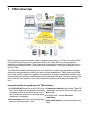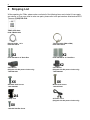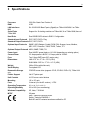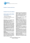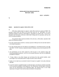
1
T/Mon LNX, MINI G2, SLIM G2
QUICK START
Visit our website at www.dpstelecom.com for the latest PDF manual and FAQs.
August 27, 2015
D-QS-TMLNX-12001
Revision History
August 27, 2015
Updated screen shots
February 27, 2014
Added browser compatability info
February 4, 2014
Initial Release
This document contains proprietary information which is protected by copyright. All rights are reserved. No part of this
document may be photocopied without prior written consent of DPS Telecom.
All software and manuals are copyrighted by DPS Telecom. Said software and manuals may not be reproduced, copied,
transmitted or used to make a derivative work, by either mechanical, electronic or any other means in whole or in part, without
prior written consent from DPS Telecom, except as required by United States copyright laws.
© 2015 DPS Telecom
Notice
The material in this manual is for information purposes and is subject to change without notice. DPS Telecom shall not be
liable for errors contained herein or consequential damages in connection with the furnishing, performance, or use of this
manual.
Contents
Visit our w ebsite at w w w .dpstelecom .com for the latest PDF m anual and FAQs
1 T/Mon Overview
1
2 Shipping List
2
3 Specifications
3
4 Hardware Installation
4
4.1 Mounting
4
4.2 Power Connection: -48VDC
7
4.3 Power Connection: 110VAC
7
5 Initial Setup
8
5.1 Changing T/Mon's IP Address via Serial Connection
5.2 LAN Connection
5.2.1
Configuring the NIC Interfaces
8
10
11
5.3 Network Time Protocol (NTP)
14
5.4 Create Shortcut to the Legacy T/Mon Administrative Console
15
5.4.1
Alternative Method to Create Shortcut
16
5.5 Loading Existing T/Mon Database
19
6 Optional Software Module: SQL Agent
22
6.1 Internal Alarms
22
6.2 Performance Stats in Monitor Mode
22
6.3 Adding New Users to the SQL Server
23
6.4 Data Dictionary
24
7 Optional Software Module: Site Dialer for T/Mon
27
7.1 Step 1: Setup the Voice Pager Job
27
7.2 Step 2: Setup the Site Dialer RTU Job
28
7.3 Step 3: Create the Site Dialer Device
29
7.4 Step 4: Setup Pager Carriers
29
7.5 Step 5: Define Voice Format
30
8 T/Mon Web 3.0
8.1 Standing / COS Alarms
31
32
8.1.1
View Detail
32
8.1.2
Trouble Log
33
8.1.3
Ack (Acknowledge)
33
8.1.4
Silence
34
8.2 Ports / Jobs
8.2.1
Dialup Device Stats Monitor
35
36
8.3 Controls
36
8.4 Silence
37
8.5 Analog Groups
8.5.1
Analog Trending Graphs
37
39
8.6 History Reports
41
9 Reference Section
44
9.1 Updating T/Mon Software
44
9.2 Powering Down or Rebooting
46
10 Technical Support
46
11 T/Mon Gold and Platinum Plans
47
12 End User License Agreement
48
1
1 T/Mon Overview
DPS is proud to announce the latest in alarm management technology - the T/Mon. It combines T/Mon
NOC and EXP technology into one, blazing fast device. The T/Mon yields a cleaner configuration,
especially for redundant systems. T/Mon features all the flexibility you expect from T/Mon, with a much
faster processor and more RAM - just to name a few enhancements - as it lays the foundation for the
future of T/Mon.
The T/Mon Remote Alarm Monitoring System is a multiprotocol, multifunction network alarm manager
designed as a single-platform solution for all alarm monitoring applications. T/Mon collects alarm data
from a wide variety of equipment, regardless of manufacturer or protocol, and displays the state of your
entire network in one interface, eliminating the need for specialized terminals. T/Access is a thing of the
past for the LNX, as it supports a fresh, new web interface offering more flexibility and visibility than
ever.
Immediate benefits of upgrading to the T/Mon platform:
6 10/100/1000 NICs versus a single 10/100 in the
NOC. With multiple LAN configurations becoming
increasingly popular for security reasons, your T/
Mon LNX can communicate on 6 networks while
maintaining IP segregation.
Completely compatible with existing T/Mon EXP
applications, such as the SQL History Agent and
Voice Dialer
On-board RAID 1 for true hard drive
redundancy
Processes more ASCII jobs, virtual polling loops,
Better multi-tasking environment to allow more,
and more GFX connections - faster
faster
2
2 Shipping List
While unpacking the T/Mon, please make sure that all of the following items are included. If some parts
are missing, or if you ever need to order new parts, please refer to the part numbers listed and call DPS
Telecom at (800) 622-3314.
T/Mon Quick Start
D-QS-TMLNX-12001
Ethernet Cable - 14 ft.
D-PR-923-10A-14
T/Access Cable (DB9 to DB9)
D-PR-1053-10A-10
X2
X2
D-CS-538-20A-01 19" Rack Ears
D-CS-538-20A-02 23" Rack Ears
4-Pin Barrier
(Shipped with DC powered units only)
1-820-00814-02
2-Pin Barrier
(Shipped with DC powered units only)
1-820-00862-02
X2
X6
Standard Rack Screws
1-000-12500-06
X6
Metric Rack Screws
1-000-80750-03
X4
5 Amp Fuse
X8
1-000-80375-02 Ear Screw
AC Power Cord
(Shipped with AC powered units only)
3
3 Specifications
Processor
2.66 GHz Quad-Core Pentium 4
RAM
4 GB
LAN Interfaces
MINI
Serial Ports
T/Mon MINI
Hard Drive
Six 10/100/1000 BaseT ports (Gigabit) on T/Mon LNX/SLIM, 2 on TMon
Standard Input Protocols
DCP, DCPf, DCPx, Ping
Support for 16 docking modules on T/Mon LNX, 8 on T/Mon SLIM, None of
Dual 500GB SATA drives in RAID 1 Configuration
Standard Output Protocols DCP, DCPf, DCPx
Optional Input Protocols
SNMP, ASCII, Badger, Cordell, DCM, E2A, Granger, Larse, Modbus,
NEC, NTP, Pulsecom, TABS, TBOS, Teltrac, TL1
Optional Output Protocols ASCII, SNMP, TABS, TL1
Power Input
Dual -48VDC power feeds or 110 VAC (depending on ordering option)
Current Draw:
3.5 Amps peak at -48VDC, 2.0 Amps peak at 110VAC
Fuse
Two 5-Amp GMT fuses (DC version only)
Dimensions:
LNX: 8.75” H x 17” W x 14” D (6 RU)
Weight
SLIM / MINI: 5.25” H x 17” W x 14” D (4RU)
28 lbs (30 lbs with slide rack)
Visual Display
Front panel LCD
Removable Storage
only
Printer Support
CD/DVD burner drive (supports CD-R, CD-RW, DVD+/-R), T/Mon LNX
Unit Controls
4 LCD menu control buttons
Mounting
19" or 23" rack
Fans
3 internal (4 in the AC version), 1 CPU
Operating Temperature
41° to 95° F (5° to 35° C)
Operating Humidity
0% to 90% (non-condensing)
Windows Compatibility
XP, Vista, 7 32/64 bit
MTBF
60 years
Via LPT printer port
EMC: Tested to EN55022/55024
Safety: Tested to EN60950-1
Both AC and DC variants have been certified for CE
4
4 Hardware Installation
4.1 Mounting
Slide Rack Mounting - Optional Accessory (T/Mon LNX only)
Slide Rack Mounting
The Slide Rack enables the T/Mon LNX to easily slide out of its rack position for installation and service
access. Your T/Mon shipped with the Slide Rack already mounted to the unit and with the specified rack
ears in the correct position for installation. Installing the T/Mon with Slide Rack takes three steps:
1. Removing the Slide Rack from the T/Mon
2. Mounting the Slide Rack on the equipment rack
3. Mounting the T/Mon on the Slide Rack.
Note: The T/Mon with Slide Rack occupies 4 rack units of space. At least 1 rack unit (1 3/4”) should be
allowed above the T/Mon for ventilation. The Slide Rack extends nearly 13” - be sure to provide
adequate service loop in the connecting cables to allow the T/Mon LNX to extend to this distance. After
installation and testing of the T/Mon is completed, the slide lock screws should be installed in the Slide
Rack to prevent accidental migration of the unit into the aisle space. The slide lock screws go into the
equipment rack when flush mounted.
Removing the Slide Rack From T/Mon LNX
Removing the Slide Rack makes mounting the T/Mon is an easy, one person, job. To remove the Slide
Rack, follow these steps:
1. Make sure the T/Mon is off and disconnected from all network interfaces and power supplies.
2. Carefully place the T/Mon upside down on a clean, even surface. (This will not damage the unit.)
3. The T/Mon is secured to the Slide Rack by two screws - see Figure 4a. Remove these screws and
save them for reattaching the unit.
4. Gently lift the Slide Rack to remove it from the T/Mon.
5
Mounting the Slide Rack - Optional
The Slide Rack is light and can easily be mounted to the equipment rack by one person. The rack ears
specified with your order (either 19” or 23”) are already attached to the Slide Rack. (If the incorrect ears
have been attached to the Slide Rack, look for the extra ears included with your shipment.) To mount
the Slide Rack to the equipment rack, follow these steps:
1. Supporting the Slide Rack with one hand, align the mounting holes in the rack ears with the rack rails.
2. Secure both brackets with the rack screws provided in the hardware bag.
Slide Rack Mounting
Mounting the T/Mon LNX on the Slide Rack
To mount the T/Mon on the Slide Rack, follow these steps:
1. Extend the Slide Rack.
2. Lift the T/Mon and place it on the Slide Rack.
Place the T/Mon on the extended Slide Rack
3. Align the notches on the bottom of the T/Mon with the mounting tabs on the Slide Rack - see
Figure 4a. There is a tab on either side of the Slide Rack, approximately 2” from the front of the
Rack. Gently place the T/Mon onto the mounting tabs.
6
There is a m ounting tab on either side of the Slide Rack approxim ately 2” from the front of the Slide Rack
4. From below the T/Mon, insert the two screws that secure the T/Mon to the Slide Rack.
5. Slide the Slide Rack back into place.
Secure T/Mon to Slide Rack
Rack Mounting
If you did not order the Slide Rack, your T/Mon is equipped with rack ears that can be positioned for
either 5” projection or flush mounting in either 23” or 19” racks. To mount the T/Mon directly to the
equipment rack, follow these steps:
1. Determine which mounting configuration is required. The T/Mon is supplied with the brackets in the
19”/5” projections position.
2. If a different configuration is required, remove the 8-32 screws, re-orient the brackets and re-install
the screws.
3. Place the T/Mon in the rack and align the mounting holes in the brackets with the holes in the rack
rails. Secure each bracket with two 12-24 screws (provided in hardware bag).
7
4.2 Power Connection: -48VDC
The T/Mon is powered by two screw terminal barrier plug power connectors.
Screw term inal barrier plugs
To connect the T/Mon to a power supply, follow these steps:
1. Always use safe power practices when making power connections. Be sure to remove fuses from
the fuse distribution panel, as well as the back of the T/Mon, before making your power connections.
2. Use the grounding lug to connect the unit to earth ground. The grounding lug is next to the symbol
.
Insert the eyelet of the earth ground cable between the two bolts on the grounding lug (Ground cable
not included).
3. Insert a battery ground into the power connector plug's right terminal and tighten the screw; then
insert a battery line to the plug's left terminal and tighten its screw.
4. Insert a fuse into the fuse distribution panel and measure voltage. The voltmeter should read between
–40 and –70VDC.
5. The power plug can be inserted into the power connector only one way to ensure the correct polarity.
Note that the negative voltage terminal is on the left and the GND terminal is on the right.
6. Insert fuse into the Power A fuse slot. The power LED should be lit green. If the LED is red, the power
connection is reversed. To confirm that power is correctly connected, the front panel LEDs will flash
RED and GREEN, indicating that the firmware is booting up.
7. Repeat steps 1 -6 for Power B connector.
4.3 Power Connection: 110VAC
These instructions apply only to T/Mon models with 110VAC power connection.
1. Insert the power cord into the power inlet on the back of
the T/Mon.
2. Connect the plug end to a 110VAC outlet.
3. Turn on the power switch on the back of the T/Mon to
start the system.
110VAC version of the T/Mon
8
5 Initial Setup
5.1 Changing T/Mon's IP Address via Serial Connection
The following script is used to configure Eth0 (main network interface). Refer to the next section to to
create and define additional interfaces.
1. Connect a null terminated serial cable (T/Access cable included with the unit) from a PC's COM port
to the T/Mon craft port.
2. Start HyperTerminal on your PC, located in the Start Menu > Programs > Accessories >
Communications. Configure a serial port with the following information:
38400 bps
8 data bits
No parity
1 stop bit
No flow control
3. Connect HyperTerminal and Press Enter. A login prompt should appear.
4. Enter the default username "dps_admin" and default password "dpstelecom" (without quotes)
5. Enter "./changeIp" (case-sensitive; type without quotes, leads with a period) and press Enter. Enter
in the new IP address, subnet, gateway, and DNS information.
9
6. Press Y to confirm the new IP address. The script will apply the new IP.
10
5.2 LAN Connection
Connect the T/Mon to your LAN by inserting a standard Ethernet cable into the "eth0" port, located on
the rear of the unit.
Connecting the T/Mon to LAN
Ethernet port pinout
11
5.2.1 Configuring the NIC Interfaces
Your main network interface, Eth0, was created in the previous step. Use the following instructions for
creating Eth1 through Eth5 (Network interfaces 2-6).
1. After giving the T/Mon an IP address, open an Internet browser and navigate to the IP at port 10000:
http://xxx.xxx.xxx.xxx:10000 (where x's aressss T/Mon's IP address)
2. Login with the default username of "dps_admin" and password "dpstelecom"
3. In the left frame, click on Networking, then click on Network Configuration.
4. In the right frame, click on Network Interfaces. Click on the Activated at Boot tab.
12
5. Click on Add a New Interface.
6. In the name field, enter the NIC label on the back of the T/Mon unit you want to use: eth1, eth2, eth3,
eth4, or eth5. NOTE: If the network is not active, don't define.
7. Click on Create and Apply.
8. The new interface should now appear on the list.
13
9. Adding gateways to new network interfaces:
Return to the Network Configuration page from Step 3. This time, click on the Routing and
Gateways icon.
Select the network interface you've just created from the drop-down menu (Eth2 in this
example). Enter the gateway information.
Select No for Act as router. Click Save to finish.
14
5.3 Network Time Protocol (NTP)
On T/Mon, time syncing is no longer handled as a job, as previously in the T/Mon NOC & IAM. If an NTP
job is defined in your existing T/Mon database, you must set it to "Halted". Use the following instructions
to setup NTP using the Webmin interface.
1. In the left navigation pane, click on Hardware, then System Time. Click on Time server sync tab.
2. Enter the IP address or host name of the NTP server you want to sync with. NOTE: If using the
host name, verify that DNS servers are defined in the previous step.
3. Define the synchronization schedule. If you are unsure how often to sync, check with your server
administrator.
4. Click the Sync and Apply button to finish. NOTE: If you are not using Network Time Protocol, but you
do want the correct time, click on the Set Time tab to enter it in manually.
15
5.4 Create Shortcut to the Legacy T/Mon Administrative Console
Important: During this process you will be prompted to install a plugin for the browser you are using.
Make sure you have the appropriate rights on that machine to install browser plugins. Use Internet
Explorer 6, 7, 8 or Firefox 3.5 and lower. Chrome and browser versions not listed are not supported by
this version of VMware.
Note: Only necessary if upgrading from a T/Mon NOC, IAM or SLIM G1.
1. Open your web browser.
2. Enter "https://xxx.xxx.xxx.xxx:8333", where the xxx is the IP address assigned to the T/Mon. (Make
sure it's https for the secure connection.)
3. Log in with "dps_admin" as the username and "dpstelecom" as the password
4. Click "Generate Virtual Machine Shortcut"
16
5. Click "Install Desktop Shortcut to TMon IDE." This will create a shortcut to the main console on your
desktop.
|
|
|
|
|
|
|
|
|
|
|
|
|
|
|
NOTE: If the popup says "VMWare Remote Console
| Plug-in is not installed", click on tbe Console tab >
|
Install plug-in.
|
|
|
|
|
|
|
|
|
6. Double click this icon and log on (the username to login is "DPS" and the password is also "DPS").
7. To direct keyboard input to the console, click anywhere in the window
8. To return keyboard input to the local machine, press CTRL-ALT.
5.4.1 Alternative Method to Create Shortcut
You can use this alternative method to create a shortcut to T/Mon Administrative Console:
1.
2.
3.
4.
Open any internet browser
Enter “http://xxx.xxx.xxx.xxx:10000”, where the xxx.is the IP address assigned to the T/Mon LNX.
Log in with “dps_admin” as the username and “dpstelecom” as the password.
Click on “Others” on the left side of the page. Then click on “Custom Commands”.
17
5. Scroll all the way to the bottom of the page and look for buttons that are labeled “Download VMWare
Plugin” and “Install Desktop Shortcut”.
6. Click on the "Download VMWare Plugin" button. Then click the link to the VMWare Plugin Installer.
18
7. Once the file has downloaded, run the installer.
8. Click on the link to “Return to commands”.
9. Click on the “Install Desktop Shortcut” button. Then click the link to the Shortcut Installer.
10. Run the file after it has downloaded.
11. Enter the IP address that was assigned to the T/MonLNX in the text box and click on the Start button
to create the shortcut.
19
12. You should now have the VMWare console shortcut on your desktop.
5.5 Loading Existing T/Mon Database
Note: Only necessary if upgrading from a T/Mon NOC, IAM or SLIM G1.
1. Open the T/Mon FTP server by right clicking on the Start Menu of the PC and selecting Explore.
2. Clear the address bar at the top and type ftp://xxx.xxx.xxx.xxx, where the x's are the IP address of
T/Mon.
3. Login to the FTP server. The user name is "dps" and password is "DPS" (both are case-sensitive).
4. Drag and drop your saved T/Mon database (archive.cfg and ctrl.cfg) into the root directory of the
FTP server. You can also click anywhere on the screen and paste your .cfg files onto the system.
20
5. Once the files are pasted into the T/Mon, it will take T/Mon approximately 10 minutes (depending on
the size of your database) to convert it over to the T/Mon format.
21
6. Take T/Mon out of monitor mode by pressing ESC, R, Enter and go to Files > Utilities > Restore
Data Files. Restore the C-Configuration files from the C drive.
7. Hit Enter when you see the message "Insert Disk #1 and press <Enter>"
8. Now that your database has been restored, there are a couple differences between the older T/Mon
and the new T/Mon that you should be aware of. The main differences that affect us are knowing
which TCP ports can no longer be used.
The following is a list of Ports that cannot be
used by T/Mon because now the is using them
“behind the scenes”:
10000
9801
9802
9803
9811
9813
8333
8222
80
20
21
Most likely the only ports that this will affect are
the FTP jobs and the HTTP Web-browser. To
work around this we must change these ports
from – to:
20 to 8020
21 to 8021
80 to 8080
To do this, escape back to the Master Menu and go to Parameters > Remote Ports. Hit F for find
and go to Job 28. Hit F1 to view all of the TCP/UDP ports being used by the system. Make sure you
enter thru the list and change the ftp ports and Web ports to the new port numbers. It is best to scan
thru the rest of the ports being used to be sure no others are on the list above.
22
6 Optional Software Module: SQL Agent
The T/Mon SQL Agent job is designed to store history events from your T/Mon in a high-speed SQL
database. Once in the SQL database, you can query T/Mon history events from any number of outside
sources. Storing history events in the SQL database makes the them easily accessible via spreadsheet
programs, database access tools, Visual Basic, and server-side web technology. You can also access
historical alarm data using the T/Mon History Reporter software module (optional).
Topology draw ing of T/Mon EXP running the SQL Agent.
6.1 Internal Alarms
The following housekeeping alarms (AKA internal alarms) are available for the T/Mon SQL Agent
(address 1):
Cannot communicate with T/Mon SQL Agent: This alarm is set when the T/Mon SQL Agent fails to
respond to the T/Mon’s keep-alive request or the T/Mon is unable to establish a TCP network
connection with the T/Mon SQL Agent. This alarm clears when the T/Mon SQL Agent successfully
responds to the T/Mon’s keep-alive request.
Cannot connect TCP with T/Mon SQL Agent: This alarm is set when the T/Mon is unable to
establish a TCP network connection with the T/Mon SQL Agent. This alarm clears when the T/Mon is
able to establish a TCP network connection with the T/Mon SQL Agent.
Excessive Errors - See Performance/Stats: This alarm is set when the T/Mon receives an
excessive amount of error messages. The purpose of this alarm is to prompt the user to look at the
Performance/Stats Window. This alarm clears when the Performance/Stats are reset (Alt-F2) or the
T/Mon is re-initialized.
SQL Server Failed - see T/Mon SQL Agent: This alarm is set when the T/Mon SQL Agent loses
communication with the SQL Server. If this happens you should check if the SQL Server is still
running. This alarm clears when the T/Mon SQL Agent restores communication with the server.
6.2 Performance Stats in Monitor Mode
The following performance statistics are displayed in the Performance/Stats Window from Monitor
Mode:
Sync Tot: Total number of history synchronization attempts.
Sync Ok: Total number of successfully completed history synchronizations.
23
Hst Evt Tot: Total number of history events sent.
Hst Evt Ok: Total number of successfully completed history events.
Time Out: Received a partial message.
No Response: Receive no message.
New CMD Err: Received an unknown command.
Msg Err: Received an invalid message.
Noise Chars: Invalid/unexpected characters.
Comm Err: Failed attempt to communicate with T/Mon SQL Agent (Keep-Alive or TCP connection).
6.3 Adding New Users to the SQL Server
By default, the dps_admin user should have access rights to the event_history table in the SQL
database. If the dps_admin user does not have access rights, or you wish to grant access rights to an
additional LNX user, you can grant access rights through your T/Mon's Webmin interface.
Note: LNX users are not the same as T/Mon users. LNX users are independently managed through
the Webmin interface.
To grant or edit access rights to the tmon_history table:
1. Log into Webmin - http://IPAddress:10000 (Username: dps_admin; Password: dpstelecom)
2. Click Servers > MySQL Database Server.
3. Click Table Permissions.
4. Click Add New Permissions in Database.
5. Enter data for the new user:
· Choose the Table you want the new user to be able to access (typically tmon_history) from the
drop-down menu
· In the Username field, select the right-most radio button (next to the open text box), and enter the
name of the user you wish to grant access to the table. (Typically dps_admin)
· Leave Hosts set to Any
· Select all table and field permissions.
24
6. Click Create to finish.
Note: If, after adding table permissions, you still cannot access the SQL Server, contact DPS
Support.
6.4 Data Dictionary
(Tm on_history) Data Dictionary field descriptions
Field Name
Fie ld T ype
IPAddr
varchar(15)
IP Address of the TMon.
PRI
IPPort
smalliant(6)
IP Port of the TMon.
PRI
0
EventDateTime
datetime
The date and time which the TMon
received the event.
PRI
0000-00-00
00:00:00
Port
smallint(6)
The port which the TMon received the
event on.
0
Address
smallint(6)
The address which the TMon received
the event on.
0
Display
smallint(6)
The display which the TMon received
the event on.
0
Point
smallint(6)
The point which the TMon received
the event on
0
EventCounter
tinyint(4)
unsigned
Forms a unique identifier when used
in conjunction with the
EventDateTime.
AckDateTime
datetime
The date and time which the event
was acknowledged. This field is only
relevant if the “Initials” field is not
blank.
YES
Initials
varchar(10)
The initials of the user that
acknowledged the alarm.
YES
The state of the event.
• ‘S’=Silenced
• ‘C’=Cleared
• ‘F’=Set
YES
AlarmState
char(1)
D e scription
ArrowN ull
Key
PRI
MUL
D e fault
0
25
AlarmLevel
char(1)
The severity level of the event.
• ‘A’=Critical
• ‘B’=Major
• ‘C’=Minor
• ‘D’=Status
SubDevice
char(3)
Name of the sub-device which
reported the event.
YES
SiteName
varchar(40)
Name of the site which reported the
event.
YES
PointName
varchar(40)
Name of the point which corresponds
to the event.
YES
AuxPointName
varchar(40)
Auxiliary name of the point which
corresponds to the event.
YES
AlarmStatus
varchar(8)
Description of the current status of the
event.
YES
DispDesc
varchar(40)
Name of the display which the TMon
received the event on.
YES
datetime
The date and time which the device
that reported the event to the TMon
received the event.
YES
Current timestamp used by Microsoft
Access.
YES
TStamp
timestamp
YES
CURRENT_
TIMESTAMP
26
Data Dictionary key nam es and field nam es
Key Name
Field Name
Collation
Cardinality
PRIMARY
PRIMARY
PRIMARY
PRIMARY
INDEX ack
INDEX ack
INDEX ack
IPAddr
IPPort
EventDateTime
EventCounter
Initials
AckDateTime
EventDateTime
A
A
A
A
A
A
A
7776
(file_list) List of dat files that can be transferred to the SQL database. Used to determ ine if the file has changed and
needs to retrieved.
Field Name
Field Type
IP Addr
Varchar(13)
FileName
TimeStamp
CRC
Varchar(15)
Varchar(30)
Varchar(30)
Description
ArrowNul
1
IP Address of T/Mon where packet
came from
Name of T/Mon DAT file
Timestamp if T/Mon DAT file
CRC of received DAT file
Key
Default
Yes
Yes
0
(tm on_history_w indow s) This table contains the w indow s associated w ith each alarm point from the tm on_history table.
Field Name
Field Type
IP Addr
Varchar(15)
IPPort
Smallinit(6)
EventDateTime
Datetime
Event Counter
Double(4
WindlDX
Smallinit(6)
Window
Smallinit(
Description
ArrowNul
1
IP Address of T/Mon where the
packets came from.
Port of the SQL connection on T/
Mon.
Key
Default
Yes
Date and Time which the T/Mon
received the event.
Forms a unique identifier when used
in conjunction with EventDateTime.
Windows index. This ranges from 1
to 8. Each alarm point on T/Mon can
be associated with up to 8 windows.
Windows value. This is the window
that an associated alarm would
report to.
Yes
0
Yes
0000-0000
00:00:00
Yes
0
Yes
0
0
(DAT_EMWIN) This table contains data from EMWIN.dat on T/Mon
Field Name
Field Type
WindIdx
WinName
WinDesc
Smallinit(6)
Varchar(15)
Varchar(41)
Description
Tmon window index
Window name
Window description
ArrowNul
1
Yes
Yes
Key
Default
Yes
0
27
7 Optional Software Module: Site Dialer for T/Mon
Most of the configuration for this application is done on the T/Mon. The Site Dialer only requires that the
hardware be setup and that the unit has an IP address.
In order for the Site Dialer application to work, you'll need the following components:
T/Mon
Site Dialer RTU for T/Mon
Site Dialer software module for the
The following steps assume you already have the following configured in your T/Mon. For help, see
Section Three in the T/Mon manual.
Pager Job
Ethernet Job
7.1 Step 1: Setup the Voice Pager Job
1. On the Remote Parameters screen (accessed from Remote Ports > Remote Ports), locate the
next available job above 47.
2. Select Voice Pager from the submenu. (This is the job that “talks” to the T/Mon.)
3. Enter a description (optional) and press Enter. You will see “No Data Connection” at the top of
the screen.
4. Go to the Data Connection Assignment screen.
5. Click Add to begin creating the assignment.
a. Type: TELNET-RAW
b. IP / Host Name: Enter 127.0.0.1 (This is the default local host name.)
c. TCP Port: 7502. (This is the default port.)
d. Description: Enter a description here, such as ‘Site Dialer MINI G2’.
e. Click Save. You’ll now be back on the Data Connection Assignment screen.
6. Select the new data connection you've just created and click Save.
28
7.2 Step 2: Setup the Site Dialer RTU Job
Figure 9b
1. On the Remote Parameters screen, locate the next available job.
2. Select Site Dialer from the submenu. (This is the job that “talks” to the Site Dialer RTU.)
3. Description is optional. Select all the defaults for Time Out, Poll Delay, Fail Threshold, Fail Poll
Cycles, and Immediate Retries.
4. Go to the Data Connection Assignment screen.
5. Click Add to begin creating the assignment.
a. Type: UDP (DPS RTU, SNMP Trap Processing, SNMP Agent)
b. TCP Port: 2001
c. Description: Enter a description here, such as “Site Dialer RTU”.
d. Click Save. You’ll now be back on the Data Connection Assignment screen.
6. Select the new data connection you've just crated and click save.
29
7.3 Step 3: Create the Site Dialer Device
1. Back on the Remote Parameters screen, click Devices to create the device.
2. Click add to enter the Device ID. The default is 1, unless you’ve changed it in the RTU. (This is
the DCP address of the RTU.)
3. Enter in the IP address and port (default is 2001) of the Site Dialer RTU.
4. Description and Site Name are optional.
5. For Device Type, select Site Dialer. (This is the only option.)
6. Select all the defaults for Displays, Poll Type and Refresh Rate.
7. Select all the defaults under Address Defaults.
7.4 Step 4: Setup Pager Carriers
1. Select Pager > Pager Carriers. This is where you add your operators, who get called when an
alarm comes in.
2. Enter in the Int (Initials) and Name for your operators.
3. For Type, select V for Voice.
4. For Pager/Phone, enter the phone number to call.
5. The ID/Delay field should be filled in for added security. This is the ID you’ll press on your phone
to acknowledge an alarm. Example: If your ID is 123, you’ll press 123# to ack an alarm from your
phone. If you did not enter in an ID, you’ll simply press # to ack.
6. Finish entering in all your operators and click Save.
30
7.5 Step 5: Define Voice Format
1. From the Pager sub-menu, select Voice Format.
2. Define what T/Mon fields you;d like to include the spoken phrase.
31
8 T/Mon Web 3.0
Overview
Navigating through T/Mon Web 3.0
The new T/Mon web interface is more intuitive than ever. Now, you can right-click on any alarm point to
perform tasks such as viewing alarm detail, analogs, silencing, and issuing controls. New keyboard
shortcuts and colored icons help you stay organized while keeping tabs on changing network
conditions. You can now use the keyboard arrow keys for navigation and sort columns by clicking the
headers. You can also hide columns on a per user basis.
Changing Pane Sizes
When viewing lots of alarm details at once, you can grab the edge of the frame drag it to be as big/
small as you like. In Web 3.0, each window is opened in a new tab. You're able to view a single tab at a
time (NOTE: Your old tab won't close when a new window is opened in a new tab).
Top-Most Menu Links - Quick Overview
Intro - Takes you to the Introduction Page
Options - Allows you to set the default
context (this is the landing page after login)
Windows - Jump to 1 of T/Mon's 1200
windows and view standing/COS counts
Analog - Allows you to create and manage analog
groups, useful for analog trending and gauges
Statistics - Request statistics
Logout - Log out of the Monitor Mode web interface
After logging into the web interface, you will use the Accordion Pane off to the left of your screen to jump
to the 5 main monitoring screens: Standing / COS Alarms, Ports / Jobs, Controls, Silence, and
Analog Groups.
32
8.1 Standing / COS Alarms
After logging in to the T/Mon web interface, you will arrive at the Standing / COS Alarm screen. The
blinking circles in the accordion pane (off to the left) indicate the highest severity for alarms under that
category.
Accordion Pane
Under the title bar, there are links to view and acknowledge other
alarms. NOTE: Some links are unavailable or grayed out when (1)
there are no alarms of that type or (2) you are already viewing that
screen, or your user rights do not permit that action.
Standing Alarms - Click to jump to Standing Alarms only.
COS Alarms - Click to jump to COS (Change of State) alarms.
Silence Window - Silences all alarms in the window you specify.
Ack Window - Acknowledges all alarms in the window you specify.
Ack Page - Acknowledges alarms currently being viewed on that web page.
Analogs - Click to see only the Standing / COS Alarms tied to an analog.
Controls - Click to see the site controls defined for this window.
8.1.1 View Detail
Viewing alarm detail allows you to see the Alarm ID, the windows the alarm is associated to, the alarm
description, and more. You can also Ack the alarm from the View Detail screen using the button in the
upper-right. NOTE: Even though the alarm has been acked, the details pane will remain open until you
close it.
33
8.1.2 Trouble Log
T/Mon's trouble log allows system operators to record what corrective action was taken for each alarm.
This feature is especially useful to prevent any confusion after shift changes.
1. To create a trouble log, right-click the alarm or hit the 'L' key.
2. Click the 'Add' button in the Add Trouble Log box.
3. Click inside the empty text field and start entering your text. The maximum number of characters that
will fit is 45 per line. NOTE: Your text is not attached to the alarm until you click the Save button.
8.1.3 Ack (Acknowledge)
Acknowledging an alarm clears it from the COS list. To Ack an alarm, right-click and choose 'Ack', or hit
the 'A' key. The COS alarm will now disappear from the list.
34
8.1.4 Silence
One of the options for Standing / COS Alarms is to Silence. This acts like a 'snooze' feature that quiets
an alarm for a certain period of time. Silencing an alarm is different than Acking (Acknowledging) the
alarm, since the alarm returns after the "snooze" period is over.
To Silence, right-click the alarm and choose 'Silence', or hit the 'S' key.
Next, you'll be prompted to choose an Expiration Date/Time. This date and time is when the alarm will
return. Use the calendar drop-down to select the date. The expiration time can be selected in
increments of 5 minutes. Click the 'Silence' button when finished. Notice that the alarm's status is now
changed to "Silenced".
35
8.2 Ports / Jobs
From the Ports / Jobs screen, you can view details such as Good vs. Bad polls at your different sites.
Simply choose which port you want to see, and view the Alarms and Analogs associated to that port.
The stats are automatically updated approximately every 5 seconds.
Right click options for the Ports / Jobs screen include Details, View Alarms, View Analogs, Poll, Toggle
Device Online/Offline.
Details - Brings up the Site Details for that particular port, such as the Alarm ID, Site Name, and Site
Address.
View Alarms - Shows you all the alarm points associated to that site.
View Analogs - Shows you any analog alarms associated to that port, including the analog gauge (if
one was selected.)
Poll - Activates a full poll to refresh status of all points in T/Mon.
Toggle Device Online/Offline - Sets device status as online or offline. Polling of site is suspended on
offline devices.
36
8.2.1 Dialup Device Stats Monitor
From the Ports / Jobs screen, you can view the status of configured / databased Dialup devices. This
screen features several additional right click menu options from the traditional Ports / Jobs screens.
Right Click Menu Options Unique to Dialup Device Stats Monitor
Reset Stats - Resets the polling stats.
Force Call - Allows you to immediately check on a site by assigning the site selected site as the next
site called. When the Force Call function is used, the Miscellaneous field will update the status.
Force Hangup - This function cancels the Force Call selection, if it is not already in progress.
Send Config - Instructs T/Mon to re-send configuration to the device.
8.3 Controls
Issuing controls is just a click away. Click on 'Controls' in the Accordion Pane. You can choose to view
controls by Site or Label.
37
Right clicking on a Control will bring up a menu where you can select Issue or Details.
8.4 Silence
Click on the 'Silence' button in the Accordion Pane to see all your currently silenced items. You will
choose whether to view silenced alarms or silenced windows.
8.5 Analog Groups
T/Mon Web 3.0 features a graphical gauge display of your analog values. The colored gauges offer a
quick, visual representation of your battery levels, temperature, humidity, voltage readings, wind speed
and much more.
The ability to create your own analog groups means you can view any assortment of these alarms and
save your grouping. You might want to see all the analog alarms at one site, or maybe you want to see
all of your temperature readings on one screen. After you have created your group, you'll choose
whether to have it saved as your own personal config (only available under your login) or as a global
group (available to all users).
1. To create an analog group,
click on 'Analog' in the Top
Menu then select 'Create
Analog Group'.
38
2. You will then need to enter a
name and description for your
new analog group. You can also
select if you want this analog
group to be a global analog
group.
3. After creating your analog
group, select your analog group
from the accordian pane on the
left. From here, you'll need to
select 'Edit Group' to enable the
gauge display of the analog
values.
4. Then, using the Analog
window on the right side of the
screen, you can select which
analogs you would like displayed
as gauges. Just double click on
the analog value and it will be
generated as a gauge display.
39
5. Once you have added the
Analogs you want to display, you
should see an interface
resembling the one to the right.
You can change the gauge style
by using the gauge type icon
(located right next to the
minimize and close icons for
each of the analog displays).
NOTE: Gauges require that
your browser supports Flash and
has a Flash plugin installed.
8.5.1 Analog Trending Graphs
Monitor Mode in Web 3.0 now features the ability to view analog data with analog trending graphs. To
view analog trending graphs, first select 'Analog Groups' from the 'Accordian Pane' and then select your
'Analog Group'. From your Analog Group interface, select 'Analog Trending'.
Double click on the available analogs in the Analogs window on the right to populate the window with
analog to display.
Once you have populated the Analog Trending interface with analogs from the desired analog group,
you will now see graphical displays of the analog data for the analogs you selected. The settings for the
40
graph are saved by the user as they edit the settings.
You can edit your graphs by clicking on the graph you wish to edit then selecting 'Edit Graph'.
From this window, you can configure your analog graphs using the various options found under Graph
Settings. You can also select one of two graph types: Line Graph or Bar Graph. You can also use the
"Combined Graphs" box on the right to combine analog data onto a single graph.
41
8.6 History Reports
New in T/Mon Web 3.0 is the ability to generate history reports using the web interface. Your reports will
be printed into PDF format or exported as a CSV or text file.
To access the web reporting interface, simply select 'Reports' from the Top Menu in Monitor Mode.
42
You can choose to generate a history report as a PDF (from the 'History' sub menu) or export a report
as a CSV file or a text file (from the 'Export' sub menu).
By selecting 'History' from the sub menu, you can select the type of history report you would like to
generate. Reports generated from this menu will be a PDF.
43
Configure your report parameters (beginning and ending date, windows, points, etc.) then select submit
to generate the PDF report.
If you would rather export a history report as a CSV file or a text file, then select 'Export' from the sub
menu.
44
If you would rather export a history report as a .csv file or a text file, then select 'Export' from the sub
menu. Selecting 'comma' will export a CSV file for your report and selecting 'tab' will export a text file for
your report. Configure your report parameters then select submit. There will be a new window that
appears when selecting 'Window Range'. Add the alarm windows you wish to include to the 'Selected'
column on the right then click 'Ok'. A link will appear on the bottom of the screen that will allow you to
download and/or view your exported report.
9 Reference Section
9.1 Updating T/Mon Software
NOTE: This update procedure requires T/Mon v6.5C10.0910 or later and proxy v1.0B10.0910 or
later. Contact DPS Tech Support at 559-454-1600 for assistance updating if you have an older version
of either software. This entire update procedure, from the transfer of the software update file to the
automatic T/Mon restart, typically lasts 5-6 minutes
1. Verify that T/Mon is in Monitor Mode.
2. Obtain a software update file from DPS Telecom. This file will follow this specific naming
convention:
lnx_exec_xxxxxx.tar.gz.
3. Start an FTP session to T/Mon (Use command-line or your preferred FTP client).
4. Log into the FTP session using any T/Mon user that has FTP access. The password is case
sensitive and will commonly consist of only capital letters.
5. If you're using the command line, enable hash by typing in "hash on" and activate binary mode by
typing "bin".
6. Transfer the software update file to T/Mon via FTP. This file name is case sensitive, and you
must not change the file name.
7. Wait 30-45 seconds for FileSync to detect the software update file.
8. Next, we'll monitor the status of the software update with Webmin. Launch Webmin and login
45
with username "dps_admin" and password "dpstelecom".
9. Click on the "System" link in the left pane.
10.Click the "System Logs" link that appears in the left pane.
11.Click the "View..." link for the "/var/log/messages" row in the center pane.
12.In the "Only show lines with text" box, type "TMonUpdate".
13.Click the "Refresh" button. The first line should now read "TMonUpdate Detected complete update
file..."
14.When the update is complete, a log entry will read "TMonUpdate: Restarting VM"
15.FileSync will now send down a TmonVM.zip file to T/Mon. This may take 2-3 minutes to complete.
Verify that "Sending T/Mon file TmonVM.zip" appears in the log.
16.Watch the VM console to verify that T/Mon restarts.
Your T/Mon software is now updated.
46
9.2 Powering Down or Rebooting
1. Login to Webmin with user dps_admin and password dpstelecom
2. Select Others->Custom Commands
3. To power down click the button for Shutdown T/MonLNX (Same for Mini/SLIM G2)
4. To reboot click the button for Reboot T/MonLNX.
10 Technical Support
DPS Telecom products are backed by our courteous, friendly Technical Support representatives, who will give
you the best in fast and accurate customer service. To help us help you better, please take the following steps
before calling Technical Support:
1. Check the DPS Telecom website.
You will find answers to many common questions on the DPS Telecom website, at http://www.dpstele.
com/support/. Look here first for a fast solution to your problem.
2. Prepare relevant information.
Having important information about your DPS Telecom product in hand when you call will greatly reduce the
time it takes to answer your questions. If you do not have all of the information when you call, our Technical
Support representatives can assist you in gathering it. Please write the information down for easy access.
Please have your user manual and hardware serial number ready.
3. Have access to troubled equipment.
Please be at or near your equipment when you call DPS Telecom Technical Support. This will help us solve
your problem more efficiently.
4. Call during Customer Support hours.
Customer support hours are Monday through Friday, from 7 A.M. to 6 P.M., Pacific time. The DPS Telecom
Technical Support phone number is (559) 454-1600.
Emergency Assistance: Emergency assistance is available 24 hours a day, 7 days a week. For emergency
assistance after hours, allow the phone to ring until it is answered with a paging message. You will be
asked to enter your phone number. An on-call technical support representative will return your call as
soon as possible.
47
11 T/Mon Gold and Platinum Plans
T/Mon Gold & Platinum Plan Support Escalation Policy
(559) 454-1600 Phone
(559) 454-1688 Fax
[email protected] Email
When you call DPS for T/Mon support under your T/Mon maintenance agreement, you'll receive the
following benefits:
1. If you call during normal DPS operating hours (7:00am to 6:00pm Pacific Standard Time), you will receive priority
tech support in front of all calls from users without a T/Mon Gold Plan. If you have an emergency situation, your
call will be prioritized to the top of the list (at uncommon times when there is a list).
2. If you call outside normal DPS operating hours with an emergency (ex. "System is Down"), you have access to
7x24x365 Tech Support. Follow the recorded voice instructions to alert the on-call technician. The on-call
technician will typically return your call within 15 minutes.
3. With your permission, DPS technicians can remotely access your T/Mon from DPS Headquarters (typically via
dialup) to facilitate diagnostics and instructions. You can follow along on your T/Mon screen as technicians
control your T/Mon.
4. If it is determined that DPS hardware is at fault, one of the following will occur at DPS' discretion:
With client consent, DPS will, on a priority basis, expedite a replacement component for the client's
qualified staff to install.
The client will ship the unit back to DPS for priority repair and return on a priority basis. When units are
received by DPS before 12:00pm, they are repaired, tested, and shipped back to the client within one
business day, provided there are no extenuating circumstances.
DPS will advance-replace the entire T/Mon unit. After receiving the new T/Mon, the client will ship the
failed unit to DPS. The unit will be repaired and shipped back to the client. Upon receiving the repaired
unit, the client will return the advance-replacement unit to DPS.
Extended Maintenance Agreement Benefits:
Half-Price or Free Hardware Upgrades
T/Mon operates 7x24x365. That’s stressful for any hardware. Plus, the DPS engineers are constantly
improving the platform. That’s 2 big reasons why you should update your T/Mon hardware regularly. T/Mon
Maintenance Agreements make it easy to get the equivalent of a brand new monitoring system every 3-5
years. You’ll stay well ahead of the mortality curve, and you’ll never get stuck using ancient technology.
Participate in our 50%-off upgrade program at the end of your third consecutive year as a Gold Plan
member, OR Participate in our free upgrade program at the end of your fifth consecutive year as a
Platinum Plan member. We’ll send you a brand new T/Mon. Just send us back the old one.
Software upgrades
Includes major release(s), plus updates throughout the life of your Gold/Platinum Plan. These major
releases are not small. They incorporate user feedback, industry best practices evolution, entirely new
capabilities, as well as the occasional code correction.
4-Day Factory Training course
Hosted at our corporate headquarters (up to 3 members from your team can attend per session - multiple
sessions per year).
Spares and standby purchase discount
Backup units are essential for disaster recovery. With a Gold/Platinum Plan, you’ll get discount prices on
purchasing spare parts and standby units.
48
12 End User License Agreement
All Software and firmware used in, for, or in connection with the Product, parts, subsystems, or derivatives thereof,
in whatever form, including, without limitation, source code, object code and microcode, including any computer
programs and any documentation relating to or describing such Software is furnished to the End User only under a
non-exclusive perpetual license solely for End User's use with the Product.
The Software may not be copied or modified, in whole or in part, for any purpose whatsoever. The Software may not
be reverse engineered, compiled, or disassembled. No title to or ownership of the Software or any of its parts is
transferred to the End User. Title to all patents, copyrights, trade secrets, and any other applicable rights shall
remain with the DPS Telecom.
DPS Telecom's warranty and limitation on its liability for the Software is as described in the warranty information
provided to End User in the Product Manual.
End User shall indemnify DPS Telecom and hold it harmless for and against any and all claims, damages, losses,
costs, expenses, obligations, liabilities, fees and costs and all amounts paid in settlement of any claim, action or
suit which may be asserted against DPS Telecom which arise out of or are related to the non-fulfillment of any
covenant or obligation of End User in connection with this Agreement.
This Agreement shall be construed and enforced in accordance with the laws of the State of California, without
regard to choice of law principles and excluding the provisions of the UN Convention on Contracts for the
International Sale of Goods. Any dispute arising out of the Agreement shall be commenced and maintained only in
Fresno County, California. In the event suit is brought or an attorney is retained by any party to this Agreement to
seek interpretation or construction of any term or provision of this Agreement, to enforce the terms of this
Agreement, to collect any money due, or to obtain any money damages or equitable relief for breach, the prevailing
party shall be entitled to recover, in addition to any other available remedy, reimbursement for reasonable attorneys'
fees, court costs, costs of investigation, and other related expenses.
“Dependable, Powerful Solutions
that allow users to monitor larger,
more complicated networks with a
smaller, less trained staff”
“Yo u r Part n ers i n Net w o rk Al arm Man ag emen t ”
www.dpstelecom.com
4955 E Yale • Fresno, CA 93727
559-454-1600 • 800-622-3314 • 559-454-1688 fax