1
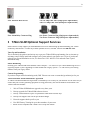
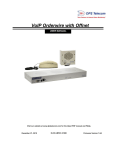
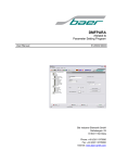
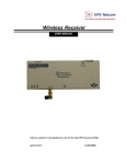
T/Mon SLIM
HARDWARE MANUAL
Visit our website at www.dpstelecom.com for the latest PDF manual and FAQs.
July 16, 2009
D-OC-UM097.16100
Revision History
September 7, 2005
T/Mon SLIM Hardware Manual released.
November 23, 2005
T/Mon SLIM Hardware Manual release. Alarm monitoring capacity
increased to 10,000 alarm points.
March 23, 2006
Editorial Changes: Fuse now reads 3/4 Amp GMT. Current Draw now
reads 500mA
September 3, 2008
Added pinout; spec clarification
July 16, 2009
Added spec clarification
This document contains proprietary information which is protected by copyright. All rights are reserved. No part of this
document may be photocopied without prior written consent of DPS Telecom.
All software and manuals are copyrighted by DPS Telecom. Said software and manuals may not be reproduced, copied,
transmitted or used to make a derivative work, by either mechanical, electronic or any other means in whole or in part,
without prior written consent from DPS Telecom, except as required by United States copyright laws.
© 2006 DPS Telecom
Notice
The material in this manual is for information purposes and is subject to change without notice. DPS Telecom shall not be
liable for errors contained herein or consequential damages in connection with the furnishing, performance, or use of this
manual.
Contents
Visit our website at www.dpstelecom.com for the latest PDF manual and FAQs
1 TMon SLIM Overview
1
2 Shipping List
2
3 T/Mon SLIM Optional Support Services
3
4 Specifications
4
5 Installation
5
5.1 Tools Needed
5
5.2 Mounting
5
5.3 Power Connection
6
5.4 Fuse Alarm Relay Output
6
5.5 LAN Connection
7
5.6 Data Ports
7
6 Getting Started with T/Mon SLIM
6.1 Connecting a PC to T/Mon SLIM with T/AccessMW
7 LCD Display
8
9
11
7.1 Boot Menu
12
7.1.1
Boot Menu Navigation Map
13
7.1.2
TLink RS232 — Choose Data Port for T/AccessMW Connection
14
7.1.3
IP Add/Gate/Sub — Edit IP Address
14
7.1.4
Restore Safe — Revert to Last Good Configuration
16
7.1.5
Hard Drives Fnd — Confirm Hard Drives Are Operational
16
7.1.6
Wshl Dsbl Launch — Prevent Automatic T/Mon SLIM Software Launch
17
7.1.7
TMon Dsbl Init — Prevent Automatic Monitor Mode Launch
17
7.1.8
TMon Del Keys — Rebuild Database Index Files
18
7.1.9
Serial Number
18
7.1.10 Resume Boot — Exit Boot Menu and Boot T/Mon SLIM
19
7.1.11 Contrast
19
7.2 Monitor Mode Menu
20
7.3 Other T/Mon Status Messages
22
7.4 W/Shell Status Messages
22
7.5 Hard Drive Recovery Status Messages
22
8 Front Panel LEDs
23
9 Troubleshooting
24
9.1 T/Mon Hard Drive Mirroring
24
9.2 Hard Drive Recovery Program
25
9.3 Abnormal Hard Drive Recovery
26
10 Technical Support
27
1
1 TMon SLIM Overview
Fig. 1.1. T/Mon SLIM
T/Mon SLIM: 1 RU Alarm Master for Real-Time Visibility of Local and Regional Networks
T/Mon SLIM is a new light-capacity, 1 RU model of the T/Mon NOC Remote Alarm Monitoring System, scaled
to the needs of small, local and regional networks. Cost-effective and easy to install, T/Mon SLIM puts high
quality network alarm monitoring within the reach of any company and any maintenance department. T/Mon
SLIM puts visibility and control of your alarms directly into your hands, giving you the power to proactively
manage the equipment and remote sites you're responsible for.
With T/Mon SLIM, you can:
·
Consolidate alarms from several sites into a single local/regional network view
·
Monitor alarms in SNMP, TL1, ASCII and nearly 20 standard, proprietary and legacy protocols*
·
Send automatic pager and email alarm notifications to technicians in the field
·
Remotely access alarms via Web browser
·
Forward alarms to a T/Mon NOC or SNMP manager at a centralized location*
·
Combine two T/Mon SLIM units in a hot standby primary-secondary geodiverse backup plan
·
Maintain alarm history logs and analyze past alarms to identify network weak spots and anticipate future
problems
·
Use Derived Alarms to track complex network problems
·
Use Derived Controls to program flexible automatic corrections for network problems
*These options require separate T/Mon software modules
Slim 1 RU design
T/Mon SLIM is a slim, 1 RU unit that fits into any 19" or 23" rack, in any telco environment, without taking
space away from revenue-generating equipment. Dual –48 VDC power inputs allow T/Mon SLIM to be powered
from the same battery power as the rest of your equipment — and give you a backup power supply in case of
primary power failure.
You don't have to trip over bulky alarm consoles — you can set up T/Mon SLIM in any equipment room and not
worry about it. Up to five users can simultaneously connect to T/Mon SLIM using its built-in Web Browser
Interface or T/Windows
T/Mon SLIM is primarily built for modern, LAN-based network environments. The unit's 10/100 BaseT Ethernet
port provides a LAN connection for receiving alarm reports from devices; forwarding alarms to T/Mon NOC or
an SNMP manager; and download T/MonXM software updates. Four RS-232 ports provide legacy polling of
serial devices.
2
2 Shipping List
Please make sure all of the following items are included with your T/Mon SLIM. If parts are missing, or if you
ever need to order new parts, please refer to the part numbers listed and call DPS Telecom at 1-800-622-3314.
T/Mon SLIM
D-PK-TMONS-120XX
T/Mon SLIM User Manual
D-OC-UM097.16100
T/Mon SLIM Software CDs
Ethernet Cable 14 ft.
D-PR-923-10A-14
RJ45-DB9 T/AccessMW Cable
D-PR-944-10A-00
23" Rack Ears
19" Rack Ears
Eight 3/8" Ear Screws
Four Rack Screws
3
/
Four Alternate Rack Screws
Two 3/4 Amp GMT Fuses (Single power input models)
Three 3/4 Amp GMT Fuses (Dual power input models)
/
Fuse Alarm Relay Connector Plug
One Power Connector Plug (Single power input models)
Two Power Connector Plugs (Dual power input models)
3 T/Mon SLIM Optional Support Services
DPS Telecom is ready support you with additional services to make turning up and maintaining your T/Mon
SLIM easy and efficient. To order any of these optional services, call DPS Telecom at 1-800-622-3314.
Turn-Up and Installation
This is absolutely the quickest and easiest way to get your T/Mon SLIM up and running. Our on-site turn-up
assistance team will help install and configure your system and train your staff to use it. Even if you haven't
ordered Turn-Up and Installation service, it's not too late. Call 1-800 622-3314 and order Turn-Up and
Installation today.
Offsite Databasing
Defining your T/Mon SLIM alarm database can be complex — let us do it for you. Offsite databasing service is
especially helpful if you're upgrading to T/Mon SLIM from a legacy system — we can convert your existing
database from your legacy master.
Custom Programming
If you have unique network monitoring needs, DPS Telecom can create a custom-design solution just for you.
T/Mon Gold Plan Annual Maintenance Agreement
A T/Mon Gold Plan Maintenance Agreement is an added layer of security for your network. It's the safest way to
ensure that your revenue-generating equipment is being protected by our newest hardware and solutions. The
T/Mon Gold Plan includes:
1.
50% off T/Mon SLIM hardware upgrades every three years
2.
Priority upgrades for T/Mon SLIM software releases
3.
Priority T/Mon hardware repair or replacement within three business days
4.
Priority tech support calls with no per-incident charges
5.
Four tech support check-up calls a year
6.
Free DPS Factory Training for up to three members of your team
7. Online access to MyDPS and T/Mon User's Group Web forums
4
4 Specifications
Protocols (Input)*:
ASCII, Badger, Cordell, DCM, DCP, DCPf, DCPx, DCM, E2A, Granger, Larse,
Modbus, NEC, NTP, Ping, Pulsecom, SNMP, TABS, TBOS, Teltrac, TL1
Protocols (Output)*:
DCP, DCPf, DCPx, SNMP
Monitoring Capacity:
64 devices/10,000 alarm points
Dimensions:
1.75" H (1 RU) x 17" W x 12" D
(4.45 cm x 43.18 cm x 30.48 cm)
Weight:
10 lbs (4.54 Kg)
Mounting:
19" or 23" rack
Power Input:
Dual –48 VDC
Current Draw:
500 mA
Fuses:
Two 3/4 Amp GMT
Serial Ports:
4 RJ45 Connectors
Serial Port Interface:
RS-232 / 33.6 Modem varies on configuration
LAN Interface:
10/100 BaseT
Processor:
400 MHz
Visual Display:
Front panel LCD, 8 bicolor LEDs
Unit Controls:
4 LCD menu control buttons
Hardware Warranty:
2 years
Operating Temperature:
50°–95° F (10°–35° C)
Operating Humidity:
0%–95% noncondensing
*Optional T/Mon Software Module(s) required to support some input/output protocols.
5
5 Installation
5.1 Tools Needed
To install T/Mon SLIM, you'll need the following tools:
Phillips No. 2 Screwdriver
Small Standard No. 2 Screwdriver
Voltmeter
PC with T/AccessMW software
5.2 Mounting
Fig. 5.2.1. T/Mon SLIM can be flush or rear-mounted
T/Mon SLIM mounts in a 19" rack or a 23" rack using the provided rack ears for each size. Two rack ear
locations are provided. Attach the appropriate rack ears in the flush-mount or rear-mount locations shown in
Figure 5.2.1.
Note: Rack ears can be rotated 90° for wall mounting or 180º for other mounting options (not shown).
6
5.3 Power Connection
Fig. 5.3.1. Power connectors and fuses
T/Mon SLIM has two screw terminal barrier plug power connectors, located on the right side of the back panel.
(See Figure 5.3.1.)
Before you connect a power supply to T/Mon SLIM, test the voltage of your power supply:
·
Connect the black common lead of a voltmeter to the ground terminal of the battery, and connect the red
lead of the voltmeter to the battery's –48 VDC terminal. The voltmeter should read between –43 and –53
VDC. If the reading is outside this range, test the power supply.
To connect T/Mon SLIM to a power supply, follow these steps:
1.
Remove the fuses from the back panel. Do not reinsert the fuse until all power connections have been
made.
2.
To ground T/Mon SLIM, connect a grounding wire to the grounding lug.
3.
Remove the power connector plug from Power Connector A. Note that the plug can be inserted into the
power connector only one way — this ensures that the barrier plug can only be reinserted with the
correct polarity. Note that the –48V terminal is on the left and the GND terminal is on the right.
4.
Insert a battery ground into the power connector plug's right terminal and tighten the screw; then
insert a –48 VDC line to the plug's left terminal and tighten its screw.
5.
Push the power connector plug firmly back into the power connector. If the power feed is connected
correctly, the LED by the connector will light GREEN. If the polarity of the power feed is reversed, the
LED by the power connector will light RED.
6.
Repeat Steps 2–4 for Power Connector B.
7.
Reinsert the fuse to power T/Mon SLIM. The front panel LEDs will blink RED and GREEN after
20–30 seconds.
5.4 Fuse Alarm Relay Output
Fig. 5.4.1. Fuse alarm relay output
The fuse alarm relay output (shown in Figure 5.4.1) is a contact closure relay output.
7
5.5 LAN Connection
Fig. 5.5.1. Ethernet port
Connect T/Mon SLIM to your LAN by inserting a standard Ethernet cable into the 10/100 BaseT port located on
the rear of the unit. (See Figure 5.5.1).
Fig. 5.5.2 Ethernet port pinout
The pinout for the 10/100 BaseT port is shown in Figure 5.5.2, above.
5.6 Data Ports
Fig. 5.6.1. Serial data ports
T/Mon SLIM has four RJ45 serial data ports on the left side of the back panel, as shown in Figure 5.6.1. These
ports connect legacy alarm monitoring equipment over an RS-232 serial interface.
Fig. 5.6.2. Serial data port pinout
Fig. 5.6.3 Telco jack pinout
The pinouts for the serial data ports and 33.6 modem are shown above.
8
6 Getting Started with T/Mon SLIM
Fig. 6.1. T/Mon SLIM, up, running and ready to go
Once the T/Mon SLIM hardware is fully installed and booted up, your next step is to define your T/Mon SLIM
database and start monitoring. Instructions for using the full T/Mon SLIM software is beyond the scope of this
hardware manual. See the T/MonXM User Manual for documentation on defining the T/Mon SLIM database and
using Monitor Mode.,
Note: The T/MonXM User Manual includes material on T/Mon NOC, IAM-5, IAM and T/MonXM WorkStation
hardware configurations that are not part of T/Mon SLIM. Some optional T/Mon functions require additional
T/Mon Software Modules. To order additional T/Mon Software Modules, call DPS Telecom at 1-800-622-3314.
To define your T/Mon SLIM database or monitor alarms with T/Mon SLIM, you need to connect a PC to the
T/Mon SLIM unit via a serial or LAN connection, using the included T/Mon remote access software. Your
T/Mon SLIM software CDs include two Windows programs for accessing T/Mon SLIM: T/AccessMW and
T/Windows.
T/AccessMW provides direct console access to T/Mon SLIM for full system administrators. With T/AccessMW
you can edit the T/Mon database as well as monitor alarms.
T/Windows provides limited client access for network monitoring personnel, and can only be used when T/Mon
SLIM is in Monitor Mode. T/Windows users cannot change the T/Mon database.
For instructions on starting T/AccessMW, see the following section, Section 6.1, "Connecting a PC to T/Mon
SLIM with T/Access." For more information about remote access to T/Mon SLIM, see the T/AccessMW and
T/Windows documentation.
9
6.1 Connecting a PC to T/Mon SLIM with T/AccessMW
This section is a brief guide to connecting to T/Mon SLIM with T/AccessMW. For full information about T/Mon
SLIM remote access, see the T/AccessMW and T/Windows documentation.
T/AccessMW runs on Windows 95, 98, ME, NT, 2000 and XP. To install T/AccessMW on your PC, use the
standard Windows installer program provided on your T/Mon SLIM software CD.
Fig. 6.1.2. T/AccessMW with no connection selected
When you first start T/AccessMW, you'll see the blank window shown in Figure 6.1.2. To connect to T/Mon
SLIM, you'll need to choose your connection type and initiate the connection.
Fig. 6.1.3 Choose Communications... from the Settings menu to get started
To choose your communications type, choose Communications... from the Settings menu (see Figure 6.1.3).
This will open the dialog box shown in Figure 6.1.4, on page 10.
10
Fig. 6.1.4 Communications Settings dialog box
Select your communications type by clicking either COM (serial connection) or Network (LAN connection) in
the Startup Connection Type area. T/AccessMW also supports Modem connections, but for initial T/Mon SLIM
setup you should use either a serial or LAN connection.
To make a serial connection to T/Mon SLIM, click COM and then choose which COM port on your PC you
want to use by clicking the appropriate button in the COM Port section. Use the supplied RJ45-to-DB9 cable to
connect your PC COM port to one of T/Mon SLIM's four back-panel data ports. By factory default, Data Port 1 is
configured as a T/AccessMW serial port. You can change which data port you use for T/AccessMW connections
using the Boot Menu. (For instructions, see Section 7.1.2, "TLink RS232 — Choose Data Port for T/AccessMW
Connection.")
To make a LAN connection to T/Mon SLIM, click Network and enter the T/Mon SLIM's IP address in the
Network IP Address box. T/Mon SLIM's default IP address is 192.168.1.1. You can change T/Mon SLIM's IP
address using the Boot Menu. (For instructions, see Section 7.1.3, "IP Add/Gate/Sub — Edit IP Address.")
Your next step is to initiate the T/AccessMW connection.
Fig. 6.1.5 Initiating a LAN connection
To start your connection to T/Mon SLIM, click the Connection menu (see Figure 6.1.5, above):
To initiate a serial connection, click COM Port.
To initiate a LAN connection, point to Network, then click Connect.
11
7 LCD Display
Fig. 7.1. T/Mon SLIM LCD showing the Standard Prompt
T/Mon SLIM's front panel LCD displays system status messages and menu commands for controlling the T/Mon
SLIM unit. You can access two separate control menus through the LCD:
1. Boot Menu: This menu is available only if you activate it shortly after booting T/Mon SLIM. (For
instructions on activating the Boot Menu, see Section 7.1, "Boot Menu.") The Boot Menu provides
commands for controlling T/Mon SLIM without starting the T/Mon SLIM software. Using the Boot
Menu is not required for normal operation of T/Mon SLIM; Boot Menu commands are only used for
initial communications setup and recovery operations. The Boot Menu is described in detail in Section
7.1, "Boot Menu."
2.
Monitor Mode Menu: This menu is available only when T/Mon SLIM is in Monitor Mode. You can
use the Monitor Mode Menu to check T/Mon SLIM unit status, standing and COS alarms, and other
options. The Monitor Mode Menu is described in detail in Section 7.2, "Monitor Mode Menu."
Both control menus are operated using the Menu, Sel, + and – buttons located near the LCD. (See Figure 7.1,
above.) For both control menus, the general operation of the control buttons is the same:
·
Use the + and – buttons to scroll through the available menu commands.
·
To select a menu command, press Sel. Selecting a command may invoke a submenu of additional
options.
·
To cancel an operation, exit from a submenu to the main menu, or to exit the control menu altogether,
press Menu.
·
If you make an invalid entry for certain Boot Menu commands, T/Mon SLIM will beep to indicate the
error.
12
7.1 Boot Menu
Fig. 7.1.1. Press Sel to start the Boot Menu
The Boot Menu provides commands for controlling T/Mon SLIM without starting the T/Mon SLIM software.
Using the Boot Menu is not required for normal operation of T/Mon SLIM; Boot Menu commands are only used
for initial communications setup and recovery operations.
The Boot Menu is available only if you activate it shortly after booting T/Mon SLIM.
To activate the Boot Menu: Power T/Mon SLIM. In approximately 20–30 seconds after the unit is powered, all
LEDs on the T/Mon SLIM front panel will blink RED and GREEN, and the LCD will display the Boot Menu
prompt shown in Figure 7.1.1, above. Press Sel to activate the Boot Menu.
Pressing Sel at the Boot Menu prompt will invoke the TLink RS232 command, which is described in Section
7.1.1. "TLink RS232." To select other commands, use the + and – buttons to scroll through the Boot Menu.
If you do not activate the Boot Menu, an automatic timeout feature will continue regular T/Mon SLIM booting.
A conceptual map of Boot Menu navigation is shown in Section 7.1.1, "Boot Menu Navigation Map."
The Boot Menu commands are described in detail in Sections 7.1.2–7.1.11, below.
13
7.1.1 Boot Menu Navigation Map
Menu
Boot Menu Prompt
Sel
TLink RS232
+
–
COM 1 ... COM 4
Sel
+/– to select, Sel to save
Menu
Menu
IP Add/Gate/Sub
Octet 1
Address
Sel
Sel
+
–
+/– to edit, Sel to save
Menu
Octet 1
Gateway
+
Sel
–
+
+/– to edit, Sel to save
Menu
Sel
Menu
+
–
Sel
+/– to edit, Sel to save
Octet 4
Sel
+/– to edit, Sel to save
–
Subnet
Restore Safe
Octet 4
Sel
Octet 1
+/– to edit, Sel to save
Sel
Octet 4
+/– to edit, Sel to save
Confirmation Prompt
Sel+ to OK, Sel– to cancel
Hard Drives Fnd
+
–
Menu
Confirmation Prompt
WShl Dsbl Launch
Sel
+
–
Sel+ to OK, Sel– to cancel
Menu
Confirmation Prompt
TMon Dsbl Init
Sel
+
–
Sel+ to OK, Sel– to cancel
Menu
Confirmation Prompt
TMon Del Keys
Sel
+
–
Sel+ to OK, Sel– to cancel
Serial Number
+
–
Menu
Confirmation Prompt
Resume Boot
Sel
+
Sel+ to OK, Sel– to cancel
–
Menu
Contrast Adjust
Contrast
Sel
+/– to select, Sel to save
Fig. 7.1.1.1. Conceptual map of the Boot Menu options
This diagram (Figure 7.1.1.1) maps the navigation of the Boot Menu commands. Use the + and – buttons to scroll
through the Boot Menu. Press Sel to enter the command submenu. Use the + and – keys to scroll through the
available options. When the option you want is displayed, press Sel again to make your selection. To cancel and
exit the command submenu, press Menu.
The Boot Menu commands are explained in detail in Sections 7.1.2-7.1.11.
14
7.1.2 TLink RS232 — Choose Data Port for T/AccessMW Connection
Fig. 7.1.2.1. TLink RS232 command
The TLink RS232 command is the first item on the Boot Menu. This command appears after you press Sel at the
Boot Menu prompt. From here you can either scroll to other Boot Menu commands by pressing the + and –
buttons, or you can edit the TLink RS232 options by pressing Sel.
Fig. 7.1.2.2. Editing TLink RS232 options
The TLink RS232 command selects which of T/Mon SLIM's four data ports is used to connect a PC to T/Mon
SLIM using T/AccessMW over an RS-232 serial connection. Selecting the TLink RS232 command invokes the
screen shown in Figure 7.1.2.2, above. The bottom line of the display shows which port is currently selected —
in this case, COM 1 (or Data Port 1).
If Data Port 1 is populated with an RS-232 port, it will be the factory default port for T/Link. However, you can
define a different data port for T/Link serial connection using W/Shell, the T/Mon SLIM shell program. If a
different port is defined for T/Link in W/Shell, it will be the first one displayed in the TLink RS232 submenu.
To select a different port, press the + or – button until the port you want is displayed.
To save your selection, press Sel.
To exit the TLink RS232 submenu without changing your COM port settings, press Menu.
Note: Defining a data port as a T/Link port suspends it for use as a T/Mon serial polling port. Once you've
defined any data port as a T/Link port, the TLink RS232 command in the Boot Menu can only reassign the
T/Link port — it cannot deactivate the T/Link port entirely. To deactivate the T/Link port, you must do so
through W/Shell. Once the T/Link port is deactivated, any T/Mon serial polling on that port automatically
resumes.
7.1.3 IP Add/Gate/Sub — Edit IP Address
Fig. 7.1.3.1. IP Add/Gate/Sub command
15
The IP Add/Gate/Sub command provides controls for editing T/Mon SLIM's IP address, gateway and subnet
settings. To edit your IP settings, press Sel at IP Add/Gate/Sub prompt screen, shown in Figure 7.1.3.1, above.
Note: The preferred way to configure IP address settings is through the Network Setup command in W/Shell, the
T/Mon SLIM shell program. T/Mon SLIM's factory default IP address is 192.168.1.1.
Fig. 7.1.3.2. IP address display. Press Sel to edit or scroll to display the gateway or subnet settings
Selecting the IP Add/Gate/Sub command invokes a screen similar to that shown in Figure 7.1.3.2. above. Note
that the number shown is prefixed with the letter "A" — this letter indicates that this is the T/Mon SLIM unit's IP
address. The IP gateway is indicated by the letter "G," and the IP subnet by the letter "S."
To edit the IP address, press Sel.
To scroll to the gateway or subnet display, press the + or – button. When you see the setting you want to
change, press Sel to edit it.
Fig. 7.1.3.3. Press + or – to change the first octet of the IP address ...
Fig. 7.1.34. ...and then press Sel to save your changes and move to the next octet
When you have selected the IP address, gateway or subnet for editing, you'll see a caret (^) cursor below the last
digit of the first octet of the number, as shown in Figure 7.1.3.3, above. You have to edit IP settings one octet
(each set of numbers between the dots) at a time. The caret shows which octet is selected for editing.
To edit, press the + or – button once to change the octet by one digit. Pressing and holding the + or – button
makes the numbers change faster, like setting the time on a digital alarm clock.
To save your changes to an octet, press Sel. The cursor will move to the next octet.
When you have saved the settings for each octet of the address, the caret cursor will disappear.
To scroll between the IP address, gateway and subnet displays, press the + or – button.
To exit the IP Add/Gate/Sub submenu, press Menu.
16
7.1.4 Restore Safe — Revert to Last Good Configuration
Fig. 7.1.4.1. Restore Safe command
The Restore Safe command reverts T/Mon SLIM to its last saved good configuration. Use this command only
when directed to do so by DPS Telecom Technical Support personnel. Executing this command will
permanently overwrite your current configuration files!
Fig. 7.1.4.2. Confirmation prompt
Press Sel to begin the Restore Safe operation. This will invoke the confirmation prompt shown in Figure 7.1.4.2,
above.
To execute the Restore Safe operation, press the Sel and + buttons simultaneously.
To cancel the Restore Safe operation, press the Sel and – buttons simultaneously.
To exit the Restore Safe submenu without executing the Restore Safe Operation, press Menu.
7.1.5 Hard Drives Fnd — Confirm Hard Drives Are Operational
Fig. 7.1.5.1. Hard Drives Fnd display
Hard Drives Fnd is a display-only command that shows which T/Mon SLIM hard drives are operational. If your
T/Mon SLIM model is equipped with only one hard drive, this display will always read "PRI Only." But if your
T/Mon SLIM model is equipped with two hard drives, this display is a useful double-check diagnostic if the
T/Mon SLIM software reports a hard drive failure.
If both hard drives are OK, the LCD will display "PRI + SEC," as shown in Figure 7.1.5.1, above. "PRI" refers
to the Primary T/Mon SLIM hard drive; "SEC" refers to the Secondary hard drive.
If the Primary hard drive has failed, the LCD will display "SEC Only."
If the Secondary hard drive has failed (or if your T/Mon SLIM is not equipped with a secondary hard
17
drive), the LCD will display "PRI Only."
7.1.6 Wshl Dsbl Launch — Prevent Automatic T/Mon SLIM Software
Launch
Fig. 7.1.6.1. WShl Dsbl Launch command
The WShl Dsbl Launch command disables an option in W/Shell (the T/Mon SLIM shell program) to
automatically launch the T/Mon SLIM software at boot. You may want to disable this option if a T/Mon software
session ends abnormally, causing a loop in which the software fails, the unit reboots, and the problem software
fails and reboots again.
Press Sel to begin the WShl Dsbl Launch operation. This will invoke the confirmation prompt previously shown
in Figure 7.1.4.2.
To execute the WShl Dsbl Launch operation, press the Sel and + buttons simultaneously.
To cancel the WShl Dsbl Launch operation, press the Sel and – buttons simultaneously.
To exit the WShl Dsbl Launch submenu without executing the WShl Dsbl Launch operation, press Menu.
7.1.7 TMon Dsbl Init — Prevent Automatic Monitor Mode Launch
Fig. 7.1.7.1. TMon Dsbl Init command
The TMon Dsbl Init command disables an option in the T/Mon SLIM software to automatically launch Monitor
Mode at startup. You may want to disable this option if a T/Mon software session ends abnormally, causing a
loop in which the software fails, the unit reboots, and the problem software fails and reboots again.
Press Sel to begin the TMon Dsbl Init operation. This will invoke the confirmation prompt previously shown in
Figure 7.1.4.2.
To execute the TMon Dsbl Init operation, press the Sel and + buttons simultaneously.
To cancel the TMon Dsbl Init operation, press the Sel and – buttons simultaneously.
To exit the TMon Dsbl Init submenu without executing the TMon Dsbl Init operation, press Menu.
18
7.1.8 TMon Del Keys — Rebuild Database Index Files
Fig. 7.1.8.1. TMon Del Keys command
The T/Mon SLIM software manages the various separate files that store the T/Mon alarm database through a
series of index files called keys. In the unlikely event that these key files lose integrity, you may be instructed by
DPS Telecom Technical Support personnel to execute the TMon Del Keys command, which deletes the key files
in order for the T/Mon SLIM software to automatically rebuild them the next time it's launched.
Press Sel to begin the TMon Del Keys operation. This will invoke the confirmation prompt previously shown in
Figure 7.1.4.2.
To execute the TMon Del Keys operation, press the Sel and + buttons simultaneously.
To cancel the TMon Del Keys operation, press the Sel and – buttons simultaneously.
To exit the TMon Del Keys submenu without executing the TMon Del Keys operation, press Menu.
7.1.9 Serial Number
Fig. 7.1.9.1. Serial Number display
Serial Number is a display-only option that shows the serial number of your T/Mon SLIM unit.
19
7.1.10 Resume Boot — Exit Boot Menu and Boot T/Mon SLIM
Fig. 7.1.10.1. Resume Boot command
The Resume Boot command exits the Boot Menu and resumes the T/Mon SLIM boot process.
Press Sel to begin the Resume Boot operation. This will invoke the confirmation prompt previously shown in
Figure 7.1.4.2.
To execute the Resume Boot operation, press the Sel and + buttons simultaneously.
To cancel the Resume Boot operation, press the Sel and – buttons simultaneously.
To exit the Resume Boot submenu without executing the Resume Boot operation, press Menu.
7.1.11 Contrast
Fig. 7.1.11.1. Contrast display
The Contrast display provides controls for adjusting the contrast of the LCD.
To adjust the contrast, press Sel, then press the + or – button until you're satisfied with the settings.
To save your selection, press Sel.
To exit the Contrast display and revert to the default contrast setting, press Menu.
20
7.2 Monitor Mode Menu
Fig. 7.2.1. Monitor Mode LCD display, showing the Standard Prompt
When T/Mon SLIM is in Monitor Mode, the LCD displays a list of system status messages. You can select what
information is displayed by using the Menu, Sel and + and – buttons.
The LCD can display six different status messages while in Monitor Mode:
The first is the Standard Prompt, which is displayed when no other menu item is selected. (See Figure 7.2.1.) The
standard prompt shows three items:
·
T/Mon software version
·
Polling status. If T/Mon SLIM is polling alarms, the word "Active" will be displayed in the standard
prompt. In redundant dual master configurations, the actively polling T/Mon SLIM will display "Active"
in the standard prompt, and the back-up T/Mon SLIM will display the word "Passive."
·
Current time
To change the LCD display, press the Menu button. The LCD display will change to show the screen below:
Fig. 7.2.2. Standing/COS Alarm Display
Standing/COS Alarm Display: This screen lists the current number of standing and change-of-state (COS)
alarms.
To see other screens, press the – button to scroll down the list. You can also press the + button to scroll the list
backwards.
In order, the remaining screens are:
Fig. 7.2.3. Run Time Mon Time Display
Run Time/Mon Time Display: This screen lists the Run Time (total system uptime since T/Mon SLIM was
powered or rebooted) and the Mon Time (total time in Monitor Mode).
21
Fig. 7.2.4. System Name and IP Address Display
System Name and IP Address Display: This screen lists the system name of this T/Mon SLIM unit and its
assigned IP address.
Fig. 7.2.5. Software Version and Serial Number Display
Software Version and Serial Number Display: This screen lists the T/Mon software version and the unit's
serial number.
Fig. 7.2.6. Contrast Display
Contrast Display: This screen provides controls for adjusting the contrast of the LCD display.
To adjust the contrast, press the + or – button until you're satisfied with the settings.
To save your selection, press Sel.
To exit the Contrast display, press Menu.
22
7.3 Other T/Mon Status Messages
Display Message
TCPAgnt Outdated
TCPAgnt Not Load
Loading TMon
Initializing
Closing Files
Offline
Halt Monitoring
Description
The version of TCP Agent currently loaded is earlier than
the earliest recommended version, TCP Agent 3.0N
TCP Agent is not loaded
T/Mon SLIM software is loading from disk
T/Mon SLIM initializing in preparation for Monitor Mode
T/Mon SLIM closing files during shut down
T/Mon SLIM currently not monitoring
T/Mon SLIM stopping Monitor Mode
Table 7.3.A. Additional T/Mon status messages
When T/Mon SLIM is fully booted, but not in Monitor Mode, other status messages will appear in the LCD
display. These status messages are described in Table 7.3.A, above.
7.4 W/Shell Status Messages
Display Message
WShell
Loading
WShell
Offline
W/Shell
Closing Files
Description
W/Shell is loading
W/Shell is loaded, but T/Mon SLIM software is offline
and not monitoring
W/Shell is closing files and exiting
Table 7.4.A. W/Shell status messages
Other status messages appear in the LCD display only when the W/Shell program is active. W/Shell status
messages are described in Table 7.4.A, above.
7.5 Hard Drive Recovery Status Messages
Field
Rebuilding PRI
File #…
Rebuilding SEC
File #…
Description
Hard Drive Recovery Program is rebuilding primary drive
“File #” line shows current file being rebuilt.
Hard Drive Recovery Program is rebuilding secondary drive
“File #” line shows current file being rebuilt.
Table 7.5.A. Hard Drive Recovery status messages
Other status messages appear in the LCD display when the W/Shell Hard Drive Recovery Program is rebuilding a
disk drive. (For more information, see Section 7, "T/Mon Hard Drive Mirroring." Hard Drive Recovery status
messages are described in Table 7.5.A, above.
23
8 Front Panel LEDs
Fig. 8.1. Front panel LEDs
T/Mon SLIM's front panel LEDs indicate unit status. LED status messages are described below in Table 8.1.A.
LED
All LEDs
Boot
LAN
COM
Remote
Status
Blinking
Green/Red
Blinking
Red/Off
Solid Red
Description
Boot Menu entry point. Press Sel button to reconfigure boot
settings or wait 5 seconds for menu timeout
User has entered boot menu. T/Mon SLIM will not continue
boot until user selects Resume Boot menu option.
T/Mon SLIM out of Monitor Mode
Solid Green
T/Mon SLIM in Monitor Mode
Blinking Green
T/Mon SLIM data transmit over LAN
Blinking Red
T/Mon SLIM data receive over LAN
Blinking Green
T/Mon SLIM data transmit over any of four serial ports
Blinking Red
T/Mon SLIM data receive over any of four serial ports
Off
Blinking
Green/Off
Blinking
Red/Off
Blinking
Green/Red
No users logged in
Only console user (via T/Access) logged in
Only remote user (via T/Windows or Web browser) logged in
Console user and remote user logged in simultaneously
Table 8.1.A. LED status message descriptions
24
9 Troubleshooting
9.1 T/Mon Hard Drive Mirroring
Fig. 9.1.1. A portion of the interior of the T/Mon SLIM, showing the primary hard drive. The secondary hard
drive is mounted below the primary.
If you have ordered a T/Mon SLIM with two hard drives, your unit supports primary-secondary hard drive
mirroring, which provides a backup in case of hard drive failure. The data written to the primary hard drive is
continuously mirrored to the secondary hard drive.
If your primary hard drive fails, your T/Mon SLIM system will automatically be restored from the secondary
drive, with minimal data loss and downtime.
If your hard drive fails, T/Mon SLIM will reboot, and an internal alarm in Monitor Mode will notify you of the
hard drive failure.
If this happens, call DPS Telecom Technical Support at (559) 454-1600 to order a replacement drive.
To set up your replacement drive, follow the instructions in the next section, Section 9.2, "Hard Drive Recovery
Program."
25
9.2 Hard Drive Recovery Program
Fig. 9.2.1. W/Shell Hard Drive Recovery Program
In most cases, replacing a failed hard drive is purely plug-and-play. All you have to do is install the new hard
drive and the W/Shell Hard Drive Recovery Program will automatically set it up for you
To install a new hard drive:
1. Shut down T/Mon SLIM and disconnect it from its power and network connections.
2. Open the T/Mon SLIM case and install the new hard drive, following the instructions that shipped with
the new drive.
3. Reconnect the T/Mon SLIM to its power and network connections and restart the unit.
The Hard Drive Recovery program will automatically start and begin setting up the new disk. The disk set-up
status will be displayed on the T/Mon NOC LCD display (see Section 7.5, "Hard Drive Recovery Status
Messages") and in T/AccessMW. (See Figure 9.2.1, above.) This is for your information only — no user action is
required to successfully set up your new hard disk.
However, under certain abnormal conditions, you may need to provide the Hard Drive Recovery Program with
additional information. (See next section, Section 9.3, "Abnormal Hard Drive Recovery.")
26
9.3 Abnormal Hard Drive Recovery
Fig. 9.3.1. The Hard Drive Recovery Program may prompt you to check the hard drive cables or select the drive
with the latest data
On rare occasions, the Hard Drive Recovery Program may not be able to determine which drive is the primary. If
that happens, the program will prompt you to provide information to resolve the problem.
If the Hard Drive Recovery Program prompts you for information, please feel free to call DPS Technical Support
at (559) 454-1600 for help in resolving the problem. Alternatively, you can correct the problem yourself by
following the on-screen instructions and prompts.
READ THE ON-SCREEN INSTRUCTIONS CAREFULLY AND FOLLOW THEM.
If the Hard Drive Recovery Program cannot determine which hard drive is the primary, it will first ask you to
check if the hard drive cables are reversed. If you answer yes, the program will prompt you to shut down T/Mon
SLIM, swap the hard drive cables, and restart T/Mon SLIM. (See Figure 9.3.1, above.)
If the hard drive cables are correctly connected, the Hard Drive Recovery Program will ask you which hard drive
has the most current data. Check in the disk information window of the Hard Drive Recovery screen (see Figure
9.3.1), where disk information, including the date of the History File, is displayed. This information will help you
decide which is the most current disk.
27
10 Technical Support
DPS Telecom products are backed by our expert Technical Support representatives, live human beings with the
training and skills to solve your problems fast. To help us help you better, please take the following steps before
calling Te chnical Support:
3
1. Check the DPS Telecom Web site.
You will find answers to many common questions on the DPS Telecom Web site, at
www.dpstelecom.com/support. Look here first for a fast solution to your problem.
2. Prepare relevant information.
Having the important information about your DPS Telecom product ready to hand will help us answer
your questions faster. Please have ready your hardware serial number and user number when you call. It's
also handy to write down all other important information about your DPS Telecom product. But if you
don't have all the information when you call, our Technical Support representatives can help you find it.
3. Have access to troubled equipment.
Please be at or near your equipment when you call DPS Telecom Technical Support. This will help us
solve your problem more efficiently.
4. Call during Customer Support hours.
Customer support hours are Monday through Friday, from 7 A.M. to 6 P.M., Pacific time. During these
hours Technical Support representatives are on duty in our fully equipped simulation lab.
DPS Technical Support Phone Number: (559) 454-1600
Emergency Assistance: Emergency assistance is available 24 hours a day, 7 days a week. For emergency
assistance after hours, allow the phone to ring until it is answered with a paging message. You will be asked to
enter your phone number. An on-call technical support representative will return your call as soon as possible.
Index
Boot Menu, 12, 13, 14, 16, 17, 18, 19
Contrast, 19
exiting, 19
Hard Drives Fnd, 16
how to activate, 12
IP Add/Gate/Sub, 14
navigation map, 13
overview, 12
Restore Safe, 16
Resume Boot, 19
Serial Number, 18
TLink RS232, 14
TMon Del Keys, 18
TMon Dsbl Init, 17
WshlDsblLaunch, 17
cables, 2
Ethernet cable, 2
RJ45-DB9 T/AccessMW cable, 2
craft port functionality, 14
custom programming, 3
DPS Telecom Factory Training, 3
Ethernet Port, 7
pinout, 7
fuse, 2
installation, 5, 6, 7
data ports, 7
fuse alarm relay output, 6
LAN connection, 7
mounting, 5
power connection, 6
tools needed, 5
IP settings, 14
editing, 14
LAN connection, 7
LCD display, 11, 12, 19, 20, 22
adjust contrast, 19, 20
basic operation, 11
Boot Menu, 12
LCD display, 11, 12, 19, 20, 22
Closing Files, 22
Halt Monitoring, 22
hard drive recovery status messages, 22
Initializing, 22
Loading TMon, 22
Monitor Mode Menu, 20
Offline, 22
overview, 11
Rebuilding PRI, 22
Rebuilding SEC, 22
TCPAgnt Not Load, 22
TCPAgnt Outdated, 22
W/Shell Closing Files, 22
WShell Loading, 22
WShell Offline, 22
LEDs, 23
Monitor Mode Menu, 20
Contrast, 20
Run Time/Mon Time, 20
Software Version and Serial Number, 20
Standard Prompt, 20
Standing/COS Alarm, 20
System Name and IP Address, 20
offsite databasing, 3
parts, 2
numbers, 2
ordering, 2
power input, 6
rack ears, 2, 5
serial ports, 7
T/AccessMW, 8, 9
setup, 9
T/Mon Gold Plan, 3
T/Mon SLIM, 1, 2, 3, 4, 6, 8, 9, 11, 14, 16, 17, 18, 23, 24, 25, 26
data ports, 14
defining database, 8
edit IP Address, 14
hard drive mirroring, 24
hard drive recovery, 25, 26
hardware upgrades, 3
T/Mon SLIM, 1, 2, 3, 4, 6, 8, 9, 11, 14, 16, 17, 18, 23, 24, 25, 26
LCD display, 11
LEDs, 23
making a craft port connection, 14
optional support services, 3
overview, 1
power connection, 6
remote access, 8, 9
serial number, 18
shipping list, 2
specifications, 4
starting software, 8
technical support, 3
troubleshooting, 16, 17, 18, 25, 26
technical support, 27
phone number, 27
website, 27
troubleshooting, 17, 18, 24, 25, 26
turnup and installation service, 3
Warranty
DPS Telecom warrants, to the original purchaser only, that its products a) substantially conform to DPS' published
specifications and b) are substantially free from defects in material and workmanship. This warranty expires two years from
the date of product delivery with respect to hardware and ninety days from the date of product delivery with respect to
software. If the purchaser discovers within these periods a failure of the product to substantially conform to the specifications
or that the product is not substantially free from defects in material and workmanship, the purchaser must promply notify
DPS. Within reasonable time after notification, DPS will endeavor to correct any substantial non-conformance with the
specifications or substantial defects in material and workmanship, with new or used replacement parts. All warranty service
will be performed at the company's office in Fresno, California, at no charge to the purchaser, other than the cost of shipping
to and from DPS, which shall be the responsiblity of the purchaser. If DPS is unable to repair the product to conform to the
warranty, DPS will provide at its option one of the following: a replacement product or a refund of the purchase price for the
non-conforming product. These remedies are the purchaser's only remedies for breach of warranty. Prior to initial use the
purchaser shall have determined the suitability of the product for its intended use. DPS does not warrant a) any product,
components or parts not manufactured by DPS, b) defects caused by the purchaser's failure to provide a suitable installation
environment for the product, c) damage caused by use of the product for purposes other than those for which it was designed,
d) damage caused by disasters such as fire, flood, wind or lightning unless and to the extent that the product specification
provides for resistance to a defined disaster, e) damage caused by unauthorized attachments or modifications, f) damage
during shipment from the purchaser to DPS, or g) any abuse or misuse by the purchaser.
THE FOREGOING WARRANTIES ARE IN LIEU OF ALL OTHER WARRANTIES, EXPRESS OR IMPLIED,
INCLUDING BUT NOT LIMITED TO THE IMPLIED WARRANTIES OF MERCHANTABILITY AND FITNESS FOR
A PARTICULAR PURPOSE.
In no event will DPS be liable for any special, incidental, or consequential damages based on breach of warranty, breach of
contract, negligence, strict tort, or any other legal theory. Damages that DPS will not be responsible for include but are not
limited to, loss of profits; loss of savings or revenue; loss of use of the product or any associated equipment; cost of capital;
cost of any substitute equipment, facilities or services; downtime; claims of third parties including customers; and injury to
property.
For an additional fee DPS may, at its option, make available by written agreement only an extended warranty providing an
additional period of time for the applicability of the standard warranty.
Technical Support
If a purchaser believes that a product is not operating in substantial conformance with DPS' published specifications or there
appear to be defects in material and workmanship, the purchaser should contact our technical support representatives. If the
problem cannot be corrected over the telephone and the product and problem are covered by the warranty, the technical
support representative will authorize the return of the product for service and provide shipping information. If the product is
out of warranty, repair charges will be quoted. All non-warranty repairs receive a 90-day warranty.
Free Tech Support is Only a Click Away
Need help with your alarm monitoring? DPS Information Services are ready to
serve you … in your email or over the Web!
www.DpsTelecom.com
Free Tech Support in Your Email: The Protocol Alarm Monitoring Ezine
The Protocol Alarm Monitoring Ezine is your free email
tech support alert, delivered directly to your in-box
every two weeks. Every issue has news you can use
right away:
•
Expert tips on using your alarm monitoring
equipment — advanced techniques that will save
you hours of work
•
Educational White Papers deliver fast informal
tutorials on SNMP, ASCII processing, TL1 and
other alarm monitoring technologies
•
New product and upgrade announcements keep
you up to date with the latest technology
•
Exclusive access to special offers for DPS
Telecom Factory Training, product upgrade offers
and discounts
To get your free subscription to
The Protocol register online at
www.TheProtocol.com/register
Free Tech Support on the Web: MyDPS
MyDPS is your personalized, members-only online resource.
Registering for MyDPS is fast, free, and gives you exclusive
access to:
•
•
•
•
Firmware and software downloads and upgrades
Product manuals
Product datasheets
Exclusive user forms
Register for MyDPS online at
www.DpsTelecom.com/register
(800) 622-3314 • www.DpsTelecom.com • 4955 E. Yale Avenue, Fresno, California 93727