1
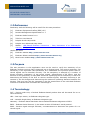
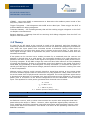
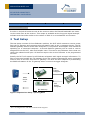
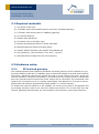
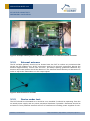
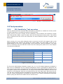
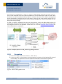
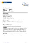
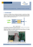
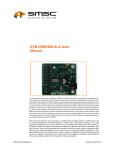
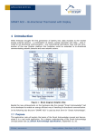
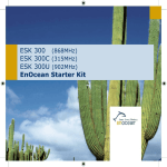
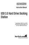
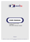
APPLICATION NOTE 008
RF Receiver Sensitivity
Performing Validation
1 Introduction
Radio frequency (RF) test equipment is often prohibitively expensive and test engineers
may not have RF expertise available to them. This leads to a lack of verification of the RF
performance in a device. As a result devices end up exhibiting poor range characteristics
that are not circumvent able as the issue lies in the underlying design. EnOcean has developed software tools that will allow you to validate the receiver performance with limited RF
engineering support while utilizing on-hand hardware.
1.1 Table of contents
1
2
Introduction ........................................................................................................ 1
1.1
Table of contents .......................................................................................... 1
1.2
References ................................................................................................... 2
1.3
Purpose ....................................................................................................... 2
1.4
Terminology ................................................................................................. 2
1.5
Theory ......................................................................................................... 3
Test Setup ........................................................................................................... 4
2.1
Required materials ........................................................................................ 5
2.2
Hardware setup ............................................................................................ 5
2.2.1
RF isolated gateway ................................................................................ 5
2.2.2
External antenna .................................................................................... 6
2.2.3
Device under test .................................................................................... 6
2.2.4
EnOcean gateway ................................................................................... 7
2.3
Firmware setup ............................................................................................. 7
2.3.1
RF shielded gateway ................................................................................ 7
2.3.2
Device under test .................................................................................... 7
2.3.3
EnOcean Gateway ................................................................................... 7
2.4
Software setup ............................................................................................. 7
2.5
Test procedure ............................................................................................. 8
2.5.1
RX_Sensitivity_Test overview ................................................................... 8
2.5.2
Procedure .............................................................................................. 9
2.5.3
Alternative Procedure ............................................................................ 13
2.5.4
Conclusions .......................................................................................... 13
© EnOcean | www.enocean.com
Subject to modifications | Bryan Edelman | January 2013 | Page 1/ 14
APPLICATION NOTE 008
RF RECEVER SENSITIVITY
PREFORMING VALIDATION
1.2 References
Familiarity with the following will be useful for this test procedure:
[1.]
EnOcean Equipment Profiles (EEP) v2.5
[2.]
Remote Management Specification v1.7
[3.]
EnOcean Radio Protocol v1.0
[4.]
TCM 3xx User Manual
[5.]
Dolphin Studio Help Guide
[6.]
Dolphin View Advanced Help Guide
[7.]
AN602 - USB Based EnOcean Transceiver – Easy Realization of an EnOcean/PC
Gateway (PDF), 12/2010
Useful web sites:
[8.]
EnOcean website http://www.enocean.com
[9.]
EnOcean Alliance website http://www.enocean-alliance.org
[10.]
MiniCircuits website http://www.minicircuits.com
1.3 Purpose
The test procedure in this application note can be used to verify the sensitivity of an
EnOcean wireless receiver that is designed into a finished good. The receive sensitivity (RX
sensitivity) is an important radio parameter as it establishes the minimum power that received signals can be decoded correctly. The RX sensitivity is affected by a number of
things including consistency of the power supply, effectiveness of RF filters, and the
amount of self generated, in-band EMF emissions. Qualifying the RX sensitivity is useful for
determining the ability of the DUT to receive wireless signals, ultimately becoming a parameter in the link budget and determining the maximum operating distance between two
devices. This level can also be compared to the RX sensitivities of the individual EnOcean
modules to evaluate how successful the end design is.
1.4 Terminology
DUT – Device under test, a finished EnOcean based product that will be tested for its receive sensitivity.
1BS – One byte sensor, an EnOcean telegram type.
VLD – Variable length data, an EnOcean telegram type.
Gateway – EnOcean based hardware that translates EnOcean telegrams to ESP3.
ESP3 – EnOcean Serial Protocol 3, the latest version of EnOcean’s serial protocol.
RSSI – Receive signal strength indicator, a measurement to determine the power of a received signal.
© EnOcean | www.enocean.com
Subject
Subject
to modifications
to modifications
| Wolfgang
| Bryan Edelman
Bihlmayr | January 2013 | Page 2/ 14
APPLICATION NOTE 008
RF RECEVER SENSITIVITY
PREFORMING VALIDATION
LTRSSI – Long term RSSI, a measurement to determine the ambient power levels of the
frequency used in the DUT.
Trigger Telegrams – 1BS telegrams with 0xBE as the data byte. These trigger the DUT to
transmit RSSI VLD debug telegrams.
Transmit Gateway – RF isolated gateway that will be sending trigger telegrams to the DUT
via Dolphin View Advanced.
Receive Gateway – Gateway that will be receiving VLD debug telegrams from the DUT via
Dolphin View Advanced.
1.5 Theory
In order for an RF signal to be received it needs to be detected, and then decoded. By
measuring ambient wireless power levels the receiver can detect the beginning of transmission, when the input power level increases across a threshold. During times when no
transmissions are occurring this power level is known as the noise floor, or long term receive signal strength value. It represents the power received from emitters other than the
intended transmitter.
If the power at the receiver has a sudden increase for a sustained time the receiver can
attempt to decode this as a valid signal. The successful decoding of a radio telegram depends on the ratio of the power of the signal to the power of the noise (SNR) at the receiver during reception. If the SNR is large the noise will have little influence on the probability
of correct bit detection. If there is a significant noise level relative to the signal, and thus a
small SNR, the probability of decoding bits correctly decreases. To maximize the power received good RF layout and antenna design practices should be followed. Limiting the noise
is more complicated.
Without noise a receiver could correctly decode a signal that arrives at the tiniest power
level and wireless signals could be received at very long distances. Many noise sources exist at the lowest level of physics and cannot be mitigated. The most significant noise source
is thermal noise because it is constant over time and exists at every frequency. This noise’s
power level is a function of the devices temperature and the bandwidth of the receivers
input. The equation for noise power generated from thermal noise is below.
Freq:
315MHz
868MHz
902MHz
-119.1
-119.1
-119.1
Table 1 - Noise Floors
An EnOcean receiver, with no other noise sources can receive radio telegrams that have
power above the values in Table 1. However, other significant signal quality reducers do
exist; amplifiers and filters introduce noise and attenuation while decoders require a minimum power above the noise floor. This allows us to arrive at the operating noise floor of
EnOcean receivers.
© EnOcean | www.enocean.com
Subject
Subject
to modifications
to modifications
| Wolfgang
| Bryan Edelman
Bihlmayr | January 2013 | Page 3/ 14
APPLICATION NOTE 008
RF RECEVER SENSITIVITY
PREFORMING VALIDATION
Freq:
1
315MHz
868MHz
902MHz
-98
-96
-98
Table 2 - EnOcean modules RX sensitivities
In order to include all noise sources at the receiver within the filtered bandwidth we measure the noise floor at the receiver. This output is available as the long term signal strength
indicator and should be similar to the values in Table 2 in an isolated RF environment.
2 Test Setup
The test setup consists of three EnOcean modules, the DUT which measures receive power
from the TX gateway and transmits this information back to the rx gateway device. The RF
shielded gateway device sends radio telegrams in conjunction with Dolphin View Advanced
operating on a connected computer. A second EnOcean gateway will be used to receive
telegrams from the DUT, also with Dolphin View. This can be any EnOcean device that can
utilize the onboard serial port. All devices require the correct firmware to be programmed
on them.
Initially the DUT will respond to all EnOcean telegrams with signal strength information. To
filter out devices besides the TX gateway device the remote management action command
must be sent to the DUT from the TX gateway. The DUT will then respond by transmitting
the RSSI information of the TX gateway when it receives a trigger telegram.
Shielded TX Gateway
1BS
Trigger
Telegram
DUT
ESP3
Serial
Link
VLD
Debug
Telegram
RX Gateway
Figure 1 Simplified Test Setup – Operating Mode
1
For 0.1% telegram loss with three transmitted sub-telegrams
© EnOcean | www.enocean.com
Subject
Subject
to modifications
to modifications
| Wolfgang
| Bryan Edelman
Bihlmayr | January 2013 | Page 4/ 14
APPLICATION NOTE 008
RF RECEVER SENSITIVITY
PREFORMING VALIDATION
2.1 Required materials
1) The device under test
2) A TCM320 with external SMA antenna connector (shielded gateway)
3) A TCM3xx with Serial output or USB300 (gateway)
4) An external antenna
5) Dolphin View Advanced
6) RF isolation box or Faraday cage
7) EVA300 development board or similar hardware
8) EOPX programmer board including cables
9) Dolphin Sniffer Firmware (Via Dolphin View Advanced)
10) RX_Sensitivity_Test Firmware (*.hex and *_cfg.hex)
11) RF attenuators designed for the test frequency
2.2 Hardware setup
2.2.1
RF isolated gateway
The TCM320 gateway and supporting hardware should be placed in an RF isolation box (ungrounded floating metal box) or faraday cage to reduce RF leakage from PCB traces and RF
connectors. Otherwise spurious RF signals can leak out and change the power levels the
receiver measures. With the transmitter in RF isolation all the receive power is transmitted
from the external antenna where the power output will be controlled. The transmitter also
needs to be connected to a PC to interact with Dolphin View Advanced. This can be accomplished with the EnOcean programming board (EOPX) or a custom solution.
To enable the external antenna on the TCM320 its circuitry may need to be adjusted and
the existing antenna needs to be removed. Please see section 4.3.2 of the TCM 320 user
manual, Mounting 50Ω antennas, for more details on this step as it varies with frequency.
© EnOcean | www.enocean.com
Subject
Subject
to modifications
to modifications
| Wolfgang
| Bryan Edelman
Bihlmayr | January 2013 | Page 5/ 14
APPLICATION NOTE 008
RF RECEVER SENSITIVITY
PREFORMING VALIDATION
Figure 2. Example Gateway device in RF shielded enclosure with external antenna connector
2.2.2
External antenna
The RF isolated gateway should not be located near the DUT to reduce any emissions that
escape the RF isolation box. All RF connectors need to be securely connected, placing the
antenna approximately 100cm from the DUT. As always spacing guidelines between any
antenna and metal planes should be observed. The antenna should be easy to disconnect in
order to adjust the attenuation on the output signal.
Figure 3. External Antenna and DUT
2.2.3
Device under test
The DUT should be orientated as it would be once installed. It should be operating from the
on board power supply and any other peripheral hardware if possible. Placement should be
at least 1m from potential external sources of interference including power supplies for oth-
© EnOcean | www.enocean.com
Subject
Subject
to modifications
to modifications
| Wolfgang
| Bryan Edelman
Bihlmayr | January 2013 | Page 6/ 14
APPLICATION NOTE 008
RF RECEVER SENSITIVITY
PREFORMING VALIDATION
er devices, lighting drivers, electromechanical devices, and lighting fixtures unless this is
the operating environment of the DUT.
2.2.4
EnOcean gateway
This device should be placed within RF range of the DUT. Access to the serial lines are required in order to communicate with Dolphin View Advanced across ESP3. It is recommended to use a TCM3xx and the EDK development board. Alternatively please see AN602USB Based EnOcean Transceiver – Easy Realization of an EnOcean/PC Gateway (PDF),
12/2010
2.3 Firmware setup
2.3.1
RF shielded gateway
The gateway needs to be running the Dolphin Sniffer firmware. This can be programmed
into the TCM320 via the Dolphin View Advanced Firmware Download button once the correct COM port is selected in the dropdown menu.
2.3.2
Device under test
The DUT needs to be running the RX_Sensitivity_Test firmware that is provided by EnOcean. This can be programmed onto the TCM3xx using Dolphin Studio and your programming hardware interface.
2.3.3
EnOcean Gateway
This TCM3xx needs to be running the Dolphin Sniffer Firmware. Alternatively this can be a
USB300. This needs to be connected to a separate instance of Dolphin View Advanced but
can be running on the same computer as the RF isolated gateways instance of Dolphin View
Advanced.
2.4 Software setup
Dolphin View Advanced will be used to send and receive radio telegrams from the gateway
device. Select the appropriate com port and click the connect button after the Dolphin Sniffer firmware has been programmed into the TX gateway. The same applies for the RX
gateway.
© EnOcean | www.enocean.com
Subject
Subject
to modifications
to modifications
| Wolfgang
| Bryan Edelman
Bihlmayr | January 2013 | Page 7/ 14
APPLICATION NOTE 008
RF RECEVER SENSITIVITY
PREFORMING VALIDATION
2.5 Test procedure
2.5.1
RX_Sensitivity_Test overview
The RX_Sensitivity_Test firmware was developed by EnOcean to enable the receive power
of radio telegrams to be measured without using RF tools.
During start up the DUT running the RX_Sensitivity_Test firmware will transmit a single
SYS radio packet, RORG equal to 0xA4, with the four data bytes being 0x00. This allows
you to determine the ID of the DUT and filter out other EnOcean devices in Dolphin View
Advanced.
Once running, for every radio telegram that is received, the DUT will respond with a VLD
debug telegram that contains the sender ID, status, RSSI, long term RSSI, level one repeated RSSI and level two repeated RSSI of the previously received telegram. This data
can be visualized using the EEP D2-3F-DE from the debug.xml profile file in the Dolphin
View Advanced EEP tab.
Description
Size (Bytes)
Offset (Bytes)
RX Telegram RORG[1]
1
0
RX Telegram Sender ID
4
1
RX Telegram Status
1
5
RX Telegram RSSI
1
6
RX Telegram Sub Telegrams Received
1
7
DUT Long Term RSSI
1
8
Figure 4. VLD Debug Telegram Format
To focus the RSSI debug telegrams trigger only on our RF isolated gateway messages a
filter can be established via the remote management action command.[2] Whenever the
DUT receives this action command the DUT will respond with RSSI debug telegrams only if
a telegram comes from this sender ID. To confirm a successful filter addition, the DUT will
transmit a SYS telegram with the now filtered ID as the four data bytes. Note that the device will only accept the action command for 30 minutes. After this time the device will ignore all remote management commands as defined in the remote management standard.
Power cycling the device will restart this 30 minute timer.
© EnOcean | www.enocean.com
Subject
Subject
to modifications
to modifications
| Wolfgang
| Bryan Edelman
Bihlmayr | January 2013 | Page 8/ 14
APPLICATION NOTE 008
RF RECEVER SENSITIVITY
PREFORMING VALIDATION
Once filtering is established in order to trigger a RSSI debug telegram the DUT must receive a 1BS telegram, from the filtered sender ID, with its data byte equal to 0xBE. Once
the device is reset or powered off the filter is removed. Any time the remote management
action command is received the DUT will start to filter on the most recent sender’s ID. In
your test environment please ensure these remote management action commands are not
being sent during testing.
In order to remove repeaters from the test environment, which will affect RSSI values, all
transmitted telegrams will have the least significant nibble set to 0xF. This indicates that
the telegram shall not be repeated. Please see 4.2.3 of the EnOcean Radio Protocol for
more information on repeaters.
Figure 5. Example Operation of RX_Sensitivity_Debug Firmware
2.5.2
Procedure
1) Follow the steps outlined in section 2, Test Setup.
2) Locate your DUT in the Dolphin View workspace and apply the RX Debug EEP located
in the debug.xml profile file on the instance connected to the EnOcean gateway.
Figure 6. Add the Debug EEP Profile
© EnOcean | www.enocean.com
Subject
Subject
to modifications
to modifications
| Wolfgang
| Bryan Edelman
Bihlmayr | January 2013 | Page 9/ 14
APPLICATION NOTE 008
RF RECEVER SENSITIVITY
PREFORMING VALIDATION
Figure 7. EEP Debug Profile
3) To eliminate the VLD debug telegrams coming from other sources we need the DUT
to filter on the RF isolated gateway. In the remote management window of the Dolphin View connected to the TX gateway click the action button.
Figure 8 - ReMan Action Command
To confirm receiving this action telegram the DUT will reply with a SYS telegram
containing the ID of the device it is now filtering on. Confirm it is the TX gateways
ID. You will also no longer be receiving VLD debug telegrams from other EnOcean
devices that are transmitting within range upon a successful filter is added in the
DUT.
© EnOcean | www.enocean.com
Subject
Subject
to modifications
to modifications
| Wolfgang
| Bryan Edelman
Bihlmayr | January 2013 | Page 10/ 14
APPLICATION NOTE 008
RF RECEVER SENSITIVITY
PREFORMING VALIDATION
Figure 9. Start up and successful filter telegram from a DUT
4) To trigger the VLD RSSI telegrams we need to send 1BS telegrams with 0xBE as the
data. We can utilize Dolphin View’s Telegram Transmit to do this. On the Telegram
Transmit tab, on the Dolphin View associated with the RF isolated gateway, go to file
then load. Select RX_Sensitivity_Trigger.do. This file contains a loop that will automatically send a trigger telegram once per second. Please note that the least significant nibble of the status byte must be 0xF to indicate that the telegram should not
be repeated by any repeaters.
5)
Figure 10. Transmitting 1BS Trigger Telegrams
6) Start sending trigger telegrams by clicking the Execute All button. Move to the EEP
view of the receiving gateway. Now you should see steady signal strength, a constant telegram count of 3, and the long term RSSI value.
© EnOcean | www.enocean.com
Subject
Subject
to modifications
to modifications
| Wolfgang
| Bryan Edelman
Bihlmayr | January 2013 | Page 11/ 14
APPLICATION NOTE 008
RF RECEVER SENSITIVITY
PREFORMING VALIDATION
Figure 11. Operation with no attenuation, all sub telegrams received
7) In order to discover the lowest RX power that the DUT can properly decode we will
lower the power the DUT receives with the use of attenuators until sub telegrams
are lost occasionally. In this case we would expect to be able to add in ~43dB of attenuation. Continue to adjust the RX signal strength via attenuators until you begin
to lose sub telegrams. This can be considered the RX sensitivity level of the DUT.
This should be equal to or better than the LTRSSI value.
© EnOcean | www.enocean.com
Subject
Subject
to modifications
to modifications
| Wolfgang
| Bryan Edelman
Bihlmayr | January 2013 | Page 12/ 14
APPLICATION NOTE 008
RF RECEVER SENSITIVITY
PREFORMING VALIDATION
Figure 12. Operation at RX Sensitivity level
2.5.3
Alternative Procedure
The above procedure can be conducted with a USB gateway running the Dolphin Sniffer
Software in place of a TCM320, external antenna, and RF attenuators. RF power levels received at the DUT can be adjusted by physically moving the USB gateway and increasing
distance between the devices instead of using RF attenuators. Trial and error will be required to find an optimal position that sets the DUT RX power near the RX sensitivity level.
Please note that this does not qualify the maximum range and only the RX sensitivity level.
In order to analyze the VLD debug telegrams the receiving gateway should be running on a
stationary computer within RF range of the DUT which may require a second person to aid
in the completion of this application note.
2.5.4
Conclusions
Each Dolphin Module has its RX sensitivity specified in Table 2 - EnOcean modules RX sensitivities. Ideally telegrams should properly be received down to this power level. If the
DUT’s RX sensitivity is equal or less than the LTRSSI value the DUT RF receiver portion can
be considered successful.
© EnOcean | www.enocean.com
Subject
Subject
to modifications
to modifications
| Wolfgang
| Bryan Edelman
Bihlmayr | January 2013 | Page 13/ 14
APPLICATION NOTE 008
RF RECEVER SENSITIVITY
PREFORMING VALIDATION
Two possible reasons that the measured RX sensitivity will not match the specification are
that other devices are transmitting at the test frequency, and the DUT is emitting unintentional noise at the test frequency via onboard devices such as switching power supplies,
PWM drivers, or other periodic signals. Both of these are capable of corrupting RF telegrams
as they are received at the antenna of a device.
The external RF environment can be qualified without additional RF test tools by using a
known reference. This can be accomplished by loading the RX_Sensitivity_Test firmware
onto a TCM3xx module in combination with an EnOcean development board, such as the
EDK 300, and using this as a reference level. If the measured RX sensitivity is not equal to
or less than the LTRSSI value then the environment is not acceptable for testing. Move the
test setup to a different physical location where devices transmitting at the test frequency
will have less impact on the DUT.
If, in a low external noise environment, the RX sensitivity fails to reach the LTRSSI then
the device itself is generating interference and should be evaluated for unwanted emissions
from internal components and the RF design should be validated. This may require the use
of a spectrum analyzer. Please contact EnOcean for additional assistance if required.
The operating range of any wireless devices depends on the link budget. It is important to
remember that this is influenced by both the ability to receive low level signals, as discussed in this application note, and the ability to transmit efficiently. Please see AN102,
Antenna Basics – Basic Antenna Design Considerations for EnOcean based Products and
AN105, 315 MHz internal antenna design – Considerations for EnOcean based Products
(PDF), 12/2011.
© EnOcean | www.enocean.com
Subject
Subject
to modifications
to modifications
| Wolfgang
| Bryan Edelman
Bihlmayr | January 2013 | Page 14/ 14