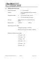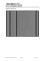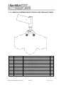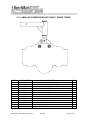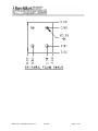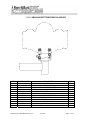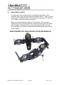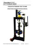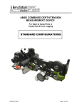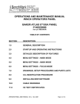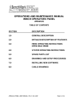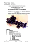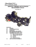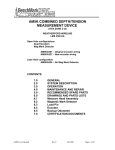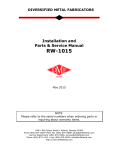
1
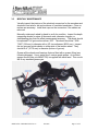
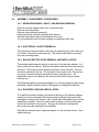
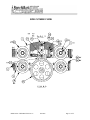
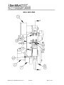
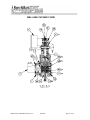
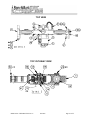
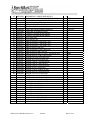
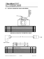
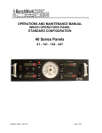
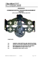
AM3KA539
COMBINED DEPTH/TENSION MEASUREMENT
DEVICE
WITH LOW VOLTAGE TENSION AMPLIFIER
CONTENTS
1.0
2.0
3.0
4.0
5.0
GENERAL DESCRIPTION AND SPECIFICATIONS
INSTALLATION AND OPERATING PROCEDURES
MAINTENANCE AND REPAIR PROCEDURES
RECOMMENDED SPARE PARTS LIST
DRAWINGS AND PARTS LISTS
AM3KA538 USER MANUAL Rev A
Jan 2009
Page 1 of 27
1.0
GENERAL DESCRIPTION AND SPECIFICATIONS
The BenchMark Measurement System AM3K measuring device combines in
one compact, lightweight unit, both depth measurement and line tension
measurement capabilities. A single measuring wheel is used to drive an
optical encoder. An electronic load axle is used to measure line tension.
1.1
DEPTH MEASUREMENT
The AM3K uses a single measuring wheel to measure the amount of
wireline moving to and from the borehole. The measuring wheel is coupled to
an encoder that transmits electrical signals via a cable to the hoistman’s
panel and/or logging computer representing cable travel. An independently
powered encoder and display panel is used for back up depth indication.
The hardened measuring wheel has a 2.0000 ft. (609.600 mm)
circumference with a 3/8" groove. A spring mounted tension roller is used to
hold the measuring wheel in contact with the wireline.
Two guide rollers are used to properly hold the cable in line with the
measuring wheel. Wear blocks are also used to guide the cable and prohibit
cable contact with the frame members. The frame members are anodized
6061-T6 aluminum.
1.2
TENSION MEASUREMENT
The AM3K uses an electronic load axle on the measuring wheel to measure
line tension. Three wheels are used to create a force on the load axle normal
to the axis of the wireline. To generate this force the wheel mounted on the
load axle is offset from the other two slightly. This offset creates a slight bend
in the cable.
As wireline tension increases the small offset creates a corresponding
bending force on the strain-gauged load axle. An electronic signal is
transmitted via cable to the hoistman’s panel and/or logging computer
representing wireline tension. A calibrate resistor is included in the load pin to
send out a signal to calibrate the computer system.
AM3KA538 USER MANUAL Rev A
Jan 2009
Page 2 of 27
1.3
GENERAL SPECIFICATIONS
WEIGHT:
30 lbs
13.6kg
LENGTH:
19.6”
500 mm
HEIGHT:
13.5”
343 mm
WIDTH:
8.2”
208 mm
CABLE BEND OVER TENSION WHEEL:
< 10 Degrees
MAXIMUM LINE TENSION:
10,000 lbs
4538 kg
MEASURING WHEEL CIRCUMFERENCE
24.000”
609.60 mm
MEASURING WHEEL CIRCUMFERENCE WITH CABLE INSTALLED
3/16” cable – 2.015 ft
7/32" cable - 2.017 ft.
1/4” cable – 2.020 ft.
9/32" cable – 2023 ft.
5/16" cable - 2.026 ft.
3/8" cable – 2.031 ft.
AM3KA538 USER MANUAL Rev A
Jan 2009
Page 3 of 27
1.4
TENSION SPECIFICATIONS
Power Requirements:
9 – 15 vdc excitation
Interface:
Strain Gauge bridge with 6 pin connector
on load pin
Temperature stability:
<=
.015% full scale / deg F on zero
<=
.02% full scale / deg F on output
Accuracy:
Within 150 lbs or 3% of actual, whichever is
greater
Maximum load:
10,000 lbs
4536 kg
Signal Output (w 5/16” cable)
72mv @12v excitation = 10,000 lbs
Shunt cal = 36 mv @ 12v excitation = 5000 lbs
Multipliers for different sizes of cable
3/16” cable – 1.45
7/32" cable – 1.38
1/4” cable – 1.22
9/32" cable – 1.08
5/16" cable – 1.00
3/8" cable – .85
AM3KA538 USER MANUAL Rev A
Jan 2009
Page 4 of 27
2.0
INSTALLATION AND OPERATING PROCEDURES
2.1
SPOOLING ARM INSTALLATION
Install the measuring head on to the spooling arm by using either the top
adapter mount assembly to mount to an overhead spooling arm or the lower
yoke floor mount assembly to mount to a floor mounted pedestal.
Following are some of the mount options:
2.1.1 AM3KA243 OVERHEAD MOUNT FOR 40MM SINGLE BAR
(ASEP SPOOLER)
AM3KA538 USER MANUAL Rev A
Jan 2009
Page 5 of 27
AM3KA243 PARTS LIST
ITEM
1
2
3
4
5
6
7
10
12
15
16
17
18
19
20
21
23
24
25
26
27
28
29
30
PART NUMBER
AM3KM124
AM3KM138
AM3KM139
AM3KM140
AM3KM155
AM3KM141
AM3KM143
AM3KM144
AMSLP088
AM3KP044
AM5KP042
AM5KP080
AMS1P046
AM3KP057
AMS1P049
AM3KP058
AMS1P065
AM3KP059
C276P037
AMS1P047
AMS1P066
C276P036
ACMU2P31
AMS1P054
DESCRIPTION
HOUSING BRG FLANGE 40MM ASEP
HUB GUIDE ASEP OH ARM
HUB GUIDE INNER ASEP OH ARM
SPACER GUIDE ASEP OH ARM
PLATE SIDE PIVOT ASEP OH ARM
PLATE CHAIN GUIDE ASEP OH ARM
ADAPTER AUTO SPOOL ASEP OH ARM
BEARING FLANGE 2 IN ID MOD
BEARING LINEAR 40MMID X 50MMOD
SCREW 1/2-13 X 3.25 SOC HD SST
SCREW 1/2-13 X 3/4 SOC HD SST
SCREW 3/8-16 X 3/4 SOC HD SST
SCREW 5/16-18 X 1 SHCS SST
SCREW 5/16-18 X 1-1/4 SOC HD
SCREW 1/4-20 X 2-1/4 SOC HD SS
SCREW 10-24 X 1-1/4 SHCS SST
NUT 1/2"-13 SS
NUT 10-24 ELASTIC STOP SST
WASHER 1/2 FLAT SST
WASHER 5/16 LOCK SS
WASHER 1/2 LOCK SS
WASHER 1/4 LOCK SS
WASHER 1/4 FLAT SS
WASHER #10 FLAT SS
AM3KA538 USER MANUAL Rev A
Jan 2009
QTY
2
1
2
1
2
1
2
2
2
2
6
4
8
2
2
3
2
3
4
8
2
2
2
6
Page 6 of 27
2.1.2 AM3KA241 OVERHEAD MOUNT USING 2X3 RECTANGULAR TUBING
ITEM
1
2
3
4
6
7
8
9
10
11
12
13
14
PART NUMBER
AM3KM055
AM3KM019
AM3KM117
AMS1P009
AM3KP045
263437000
231194000
AM3KM142
AM3KP044
C276P037
AMS1P066
AMS1P065
AM5KP075
DESCRIPTION
PLATE SIDE PIVOT OH ARM 3 WHL
PIVOT WELDMT SPOOL ARM RECT 2X3X15 DEG
SHAFT PIVOT SPOOLING ARM 10 IN
RETAINING PIN (T HANDLE)
BEARING BRZ FLANGED
ONE-PIECE CLAMP-ON COLLAR
BEARING FLANGE 1.25ID x 1.25LG
BUSHING FLANGE QUIK PIN OH ARM
SCREW 1/2-13 X 3.25 SOC HD SST
WASHER 1/2 FLAT SST
WASHER 1/2 LOCK SS
NUT 1/2"-13 SS
CHAIN SASH #35 SST
AM3KA538 USER MANUAL Rev A
Jan 2009
QTY
2
1
1
1
2
1
2
2
3
4
3
3
12
Page 7 of 27
2.1.3 AM3KA242 OVERHEAD MOUNT USING 2" ROUND TUBING
ITEM
1
2
3
4
6
7
8
9
10
11
12
13
14
PART NUMBER
AM3KM055
AMS8M019
AM3KM117
AMS1P009
AM3KP045
263437000
231194000
AM3KM142
AM3KP044
C276P037
AMS1P066
AMS1P065
AM5KP075
DESCRIPTION
PLATE SIDE PIVOT OH ARM 3 WHL
PIVOT WELDMT SPOOLING ARM RD
SHAFT PIVOT SPOOLING ARM 10 IN
RETAINING PIN (T HANDLE)
BEARING BRZ FLANGED
ONE-PIECE CLAMP-ON COLLAR
BEARING FLANGE 1.25ID x 1.25LG
BUSHING FLANGE QUIK PIN OH ARM C MOUNT SST
SCREW 1/2-13 X 3.25 SOC HD SST
WASHER 1/2 FLAT SST
WASHER 1/2 LOCK SS
NUT 1/2"-13 SS
CHAIN SASH #35 SST
AM3KA538 USER MANUAL Rev A
Jan 2009
QTY
2
1
1
1
2
1
2
2
3
4
3
3
12
Page 8 of 27
2.1.4 AM3KA244 OVERHEAD FLANGE MOUNT
ITEM
1
2
3
4
6
7
8
9
10
11
12
13
14
PART NUMBER
AM3KM055
AM3KM238
AM3KM217
AMS1P009
AM3KP045
263437000
231194000
AM3KM142
AM3KP044
C276P037
AMS1P066
AMS1P065
AM5KP075
DESCRIPTION
PLATE SIDE PIVOT OH ARM 3 WHL
YOKE PIVOT CENTER MOUNT SST
SHAFT PIVOT SPOOLING ARM 7 IN
RETAINING PIN (T HANDLE)
BEARING BRZ FLANGED 1/2ID X
ONE-PIECE CLAMP-ON COLLAR ST S
BEARING FLANGE 1.25ID x 1.25LG
BUSHING FLANGE QUIK PIN OH ARM
SCREW 1/2-13 X 3.25 SOC HD SST
WASHER 1/2 FLAT SST
WASHER 1/2 LOCK SS
NUT 1/2"-13 SS
CHAIN SASH #35 SST
AM3KA538 USER MANUAL Rev A
Jan 2009
QTY
2
1
1
1
2
1
2
2
3
4
3
3
12
Page 9 of 27
AM3KA538 USER MANUAL Rev A
Jan 2009
Page 10 of 27
2.1.5 AM3KA240 BOTTOM PEDASTAL MOUNT
ITEM
1
2
3
4
5
6
7
8
9
10
11
12
PART NUMBER
AM3KM130-1
AM3KM130-2
AM3KM029
AM3KP044
C276P037
AMS1P066
AM3KM118
AMS1P009
AM5KP075
AM5KP040
C276P035
AMS1P065
DESCRIPTION
PLATE SIDE PIVOT LEFT UNIV
PLATE SIDE PIVOT RIGHT UNIV
SPACER SST 3/4 SIDE MT 3 WHEEL
SCREW 1/2-13 X 3.25 SOC HD SST
WASHER 1/2 FLAT SST
WASHER 1/2 LOCK SS
BUSHING PLAIN QR PIN BTM MT SS
RETAINING PIN (T HANDLE)
CHAIN SASH #35 SST
SCREW 10-24 X 3/8 SOC HD SST
WASHER #10 LOCK SS
NUT 1/2"-13 SS
AM3KA538 USER MANUAL Rev A
Jan 2009
QTY
1
1
2
4
8
4
2
1
6
1
1
4
Page 11 of 27
2.2
CABLE INSTALLATION
To install cable, remove the push pin, and hinge the head open. Next
insert the cable, swing the head closed and reinsert the pin. Refer to picture.
If under load, the load will need to be removed from the pin prior to removal.
A “C” clamp can be used to remove the load.
Make sure that the head can freely sit on the wireline. If the mounting
arrangement will not let the head travel up and down freely and if the cable
puts a upward or downward force on the measuring head, this force will
cause an offset to the tension measurement which will result in an incorrect
tension reading.
HEAD OPENED FOR CABLE INSTALLATION AND REMOVAL
AM3KA538 USER MANUAL Rev A
Jan 2009
Page 12 of 27
2.3
SYSTEM OPERATION
2.3.1 Determine cable size to be used – 5/16” or 7/32”
Since the wireline cable actually bends around the measuring wheel,
the circumference of the wheel is affected by the size of the cable. To
accurately measure depth, this needs to be taken into account by
increasing the size of the wheel. The bend radius of the wireline cable
also affects the tension measurement.
These corrections are automatically made in the Kerr AMS4 Panels by
selecting the proper cable size using the menu.
To enter wheel size corrections directly, use the following wheel
circumferences:
3/16” cable – 2.015 ft.
7/32" cable - 2.017 ft.
1/4” cable – 2.020 ft.
9/32" cable – 2023 ft.
5/16" cable - 2.026 ft.
3/8" cable – 2.031 ft.
2.3.2 Install line in measuring head (refer to section 2.2).
2.3.3 Make sure line is laying slack and head is free to move and hanging
level. Press the Ten Zero Cal button and tension value should read 0.
2.3.4 Press the Ten Cal button and tension should read 5000 lbs with 5/16"
cable or 6200 lbs with 7/32" cable.
2.3.5 Press the Zero Depth button to set the depth to zero when the tool is
hanging at the zero point.
2.3.6 At this point, the system is ready to log.
AM3KA538 USER MANUAL Rev A
Jan 2009
Page 13 of 27
3.0
MAINTENANCE AND REPAIR PROCEDURES
3.1
PRE-JOB CHECK
Each time the system is used perform the following steps:
Verify that the AM3K is properly and securely attached to the spooling arm.
Several different mounting kits are available for different types of spooling
arms.
Verify that the depth measuring wheels are clean and that no groove has
been worn into the measuring wheel surface. Check the measuring and
guide wheels for looseness, play, out-of-roundness, worn or rough sounding
bearings, or other mechanical conditions that could affect measurement
accuracy. Ensure that the wheel bearings inner race is not spinning on the
shaft and that the shaft is not spinning in the bushings.
Verify that all fasteners are tight and that the ball lock pushpin is secure.
Verify that the encoder, electronic load pin, and backup counter cable are
installed and properly routed. Verify that the depth system is working by
turning the wheel and observing the hoistman’s panel and backup display
unit to indicate cable movement. The hoistman's panel and backup
display should measure 2' for each rotation of the wheel.
3.2
POST-JOB MAINTENANCE
At the completion of each job, thoroughly clean and dry the device as soon as
possible. This avoids problems caused from borehole residues transferred
from the wireline onto the measuring device. Borehole residues should be
washed from the device with a cleaning solvent such as Varsol or an
equivalent type. Rinse the device with water, dry, and wipe down with an oily
rag.
Do not pressure wash
AM3KA538 USER MANUAL Rev A
Jan 2009
Page 14 of 27
3.3
MONTHLY MAINTENANCE
Visually inspect the interiors of the electrical connectors for the encoders and
electronic load axle for dirt and evidence of insulation breakdown. Clean or
replace as necessary. Install dust caps on the connectors if the cables are
removed.
Manually rotate each wheel by hand to verify its condition. Inspect the depth
measuring wheels for signs of abnormal wear, diameter changes, or
shaft/bearing play that can affect measurement accuracy. The wheel should
be replaced if it is grooved more than .005". The wheel should be 7.639 /
7.640" (194 mm) in diameter with a 24" circumference (609.6 mm). Inspect
the two grooved guide wheels on either side of the tension wheel. They
should be 4" (101.6 mm) in diameter (bottom of groove).
Grease all the wheels and bearings that are fitted with a grease fitting (see
following diagram). Use a water proof, marine grade grease. An inverted
grease nozzle (Kerr p/n AM5KP130) is supplied with each head. This nozzle
will fit any standard grease gun.
AM3KA538 USER MANUAL Rev A
Jan 2009
Page 15 of 27
3.4
ASSEMBLY / DISASSEMBLY PROCEDURES
3.4.1 MEASURING WHEEL, SHAFT, AND BEARING REMOVAL
Remove encoder adapter and cover on opposite side.
Remove both side plates.
Remove wheel and axle assembly.
Install new wheel and axle assembly with spacers.
Reinstall side plates and encoder adapter and cover.
It is recommended that the main bearings be replaced at this time.
3.4.2 ELECTRONIC LOAD PIN REMOVAL
The electronic load pin is held in place by one retaining ring on the outer end
of its shaft. Remove the retaining ring. The load pin can then be removed
from the mounting frame.
3.4.3 BACKUP DEPTH PICKUP REMOVAL AND INSTALLATION
The backup depth magnetic pickup is mounted to the encoder adapter. It is
held in place by four screws. Remove the screws and the pickup can then be
removed. The pickup must be properly oriented to work correctly. The slot
should be oriented to the top. The top side is the encoder side. Ensure that
an o-ring is inserted between the plastic housing and the mount. An
additional o-ring is used between the connector and the housing to keep
moisture out.
If the backup display is counting backward (i.e. counting negative when going
downhole), simply rotate the pickup 180 degrees to change the direction.
3.4.4 ENCODER COUPLING INSTALLATION
To install the encoder coupling, first remove the plug in the encoder adapter.
Install one of the metal parts of the three piece coupling to the wheel shaft
and tighten it using a hex wrench. Next, install the center plastic piece on the
wheel shaft coupling. Place the other metal coupling on the encoder shaft
and set the encoder on the mount. Snug up the encoder coupling then
remove the encoder and tighten the coupling.
Reinstall the encoder with o-rings and tighten it to the encoder mount. Next
tighten the plug.
AM3KA538 USER MANUAL Rev A
Jan 2009
Page 16 of 27
4.0
RECOMMEND SPARE PARTS LIST
QTY
P/N
DESCRIPTION
1
AM5KA137
ASSY WHEEL GUIDE 4 INCH COMPOSITE
WITH BEARING
1
AM5KA164
ASSY WHEEL TENSION FIXED 35MM
WITH BEARING
1
AM5KM157
BEARING BALL FAFNIR 207PP GREASEABLE
(for AM5KA137 and AM5KA164 tension wheels)
1
AM3KA187
ROLLER ASSY PRESSURE 3/8" GROOVE
WITH BEARING
1
AM3KM002
BEARING BALL FAFNIR 200PP GREASEABLE
MOD (for AM3KA187 pressure roller)
1
AM3KA110
ASSY WHEEL MEASURING 2FT 3/8" GROOVE
(includes shaft)
2
AMS1P003
BEARING BALL 204PP GREASABLE MOD
(for measuring wheel)
1
AM3KM050
ENCODER COUPLING ASSY WITH MAGNETS
1
AM3KP203
LOAD PIN ASSY LOW VOLTAGE
1
AM5KA079
ENCODER 1200 PPR EX
1
AM5KA055
MAGNETIC PICKUP ASSY
1
AMS1P009
RETAINING PIN (T HANDLE)
1
AM5KP130
GREASE NOZZLE
AM3KA538 USER MANUAL Rev A
Jan 2009
Page 17 of 27
5.0
DRAWINGS AND PARTS LISTS
5.1
MEASURING HEAD DRAWINGS
SIDE VIEW
AM3KA538 USER MANUAL Rev A
Jan 2009
Page 18 of 27
SIDE CUTAWAY VIEW
AM3KA538 USER MANUAL Rev A
Jan 2009
Page 19 of 27
DRUM END VIEW
AM3KA538 USER MANUAL Rev A
Jan 2009
Page 20 of 27
DRUM END CUTAWAY VIEW
AM3KA538 USER MANUAL Rev A
Jan 2009
Page 21 of 27
WELL END VIEW
AM3KA538 USER MANUAL Rev A
Jan 2009
Page 22 of 27
WELL END CUTAWAY VIEW
AM3KA538 USER MANUAL Rev A
Jan 2009
Page 23 of 27
TOP VIEW
TOP CUTAWAY VIEW
AM3KA538 USER MANUAL Rev A
Jan 2009
Page 24 of 27
MEASURING HEAD PARTS LIST
ITEM
1
2
3
4
4
4
5
6
7
7
8
9
10
11
14
15
17
18
19
20
22
23
24
25
26
27
28
29
30
32
33
34
35
36
37
38
39
42
49
50
51
52
PN
AM3KA131
AM3KA132
AM3KA148
AM3KA240
AM3KA241
AM3KA242
AM3KP203
AM5KA079
AM3KM040
AM5KM057
AM3KA121
AM3KM135
AM5KM058
AM5KM011
AM5KM023
AM3KM023
AM3KA125
AM3KM156
AM5KA137
AM3KA001
AM3KA187
AM5KA164
AM3KA236
AM3KM234
AM3KM064
AM3KM154
AM3KM153
AM3KM152
AM3KM115
AM5KA055
AM5KM084
AM3KM052
AM3KM053
AM3KM043
AM3KM044
AM5KM155
AM5KM039
AM3KM049
AM5KP019
AM3KP009
AM3KP032
AM3KP039
DESCRIPTION
FRAME ASSY UPPER
FRAME ASSY LOWER
ASSY PIVOT PRESS WHEEL W/GIDE
KIT MOUNTING AM3K FLOOR
KIT MOUNTING AM3K OVERHEAD ARM 2X3 RECT
KIT MOUNTING AM3K OVERHEAD ARM 2IN ROUND
ASSY LOAD AXLE LOW VOLTAGE
ENCODER 1200 PPR EX
ADAPTER ENCODER H25D/H20 MAG BACKUP
ADAPTER ENCODER H37C/H25D
PLATE SIDE ASSY W/PRESSURE WHL
PLATE ORIENTATION LOAD PIN
COVER ENCODER ADAPTER
SHAFT TENSION ROLLER 30MM SST
SHAFT PIVOT HORIZONTAL 1/2 SST
SHAFT PIVOT PRESS ROLR 3/8 SST
MOUNT ASSY PIVOT W/TIEDOWN 3K
GUIDE REAR 3 WHEEL
ASSY WHEEL GUIDE PLAS 35MM BRG
ASSY WHEEL MEASURING 2' 3/8" GROOVE
ROLLER ASSY PRESSURE 3/8" GROOVE
ASSY WHEEL TENSN FIXD 35MM BRG
LINK ASSY LOAD PIN W/SPHER BRG
BLOCK WEAR 0.75 X 2.50 TOOLSTL W/10-24 HOLES
PLATE WEAR 3/8 X 3/4 X 1-1/2
SPOOL GUIDE REAR 3 WHEEL
BUTTON GUIDE PRESS WHL PIVOT
PLATE GUIDE PRESS WHL PIVOT
BLOCK WEAR
ASSY ENCODER BACKUP MAGNETIC
SCREW ANTI-ROTATION TENS WHEEL
BOLT SHOULDER 10MM OD SST 1/4-20 INT THD
BOLT SHOULDER 5/16 X 1/4 MOD
SPACER 10MMID X 0.57OD X 0.30W SST
SPACER .31ID X 0.57OD X 0.175W SST
BUSHING 35MM BRG W/ANTI-ROTATN
SPACER 20MMID X 1.00OD X .197W PLASTIC
GUIDE SPRING PRESS WHEEL 3 WHL
BEARING BRZ FLANGED 1/2" ID OIL IMPRG
BEARING BRZ FLANGED 3/8" ID OIL IMPRG
BEARING BRZ .50ID X .625OD X .62 LONG
BEARING SPHERICAL 5/8" ID SELF LUBE SST
AM3KA538 USER MANUAL Rev A
Jan 2009
QTY
1
1
1
0
0
0
1
1
1
0
2
1
1
4
1
1
1
1
2
1
1
2
1
2
2
1
0
2
2
0
4
1
1
1
1
0
2
2
0
0
0
0
REF
OPTION
OPTION
OPTION
OPTION
REF
OPTION
REF
LOAD PIN LINK BRG
LOAD PIN LINK
Page 25 of 27
53
54
55
57
58
59
60
61
62
63
64
65
66
67
68
71
72
73
74
75
76
77
78
79
80
81
82
83
84
85
86
87
88
90
91
92
94
95
96
97
98
99
100
AMS1P003
AM5KM157
AM3KM002
AM5KP075
AMS1P009
AM3KP014
AM3KM050
AMS1P090
AM5KP071
AMS1P014
AM5KP067
AMS1P072
AM5KP033
AM3KP018
AM3KP017
AMS1P006
AM3KP048
AM3KP015
AM5KP168
AM5KP043
AM5KP038
AM5KP045
C276P031
AMSLP025
AMS1P049
AM3KP054
AMS1P048
AMSLP060
AM3KP028
AMS1P053
C276P331
AMS1P046
AM3KP070
AMS1P054
C276P039
C276P513
AMS1P047
AM5KP144
C276P035
C276P046
AM5KP048
AM3KP059
AM5KP130
BEARING BALL 20MM ID MOD W/HOLE
BEARING BALL 35MM ID MOD GREASE HOLE
BEARING BALL 10MM ID MOD GREASE HOLE
CHAIN SASH #35 SST
RETAINING PIN (T HANDLE)
SPRING COMP 3-1/8 OAL 3/4 DIA SST
COUPLING ENCDR W/BKUP MAGNETS
COUPLING OLDHAM ENCODER
O-RING 2-141 BUNA N H25 ENCDR
O-RING 2-152 BUNA N ENC ADPTR
DUST CAP CWL
PLUG 3/8 NPT SS
RING RETNG EXT 0.500 SHAFT SST
RING RETNG EXT 1.188 SHAFT SST
RING RETNG EXT 0.781 SHAFT SST
RING RETNG INT UR187S
RING RETNG EXT 0.375 E-RING SST
RING RETNG INT UR-118S SST
RING RETNG INT 2.875 LT DUTY .039 THICK SST
SCREW 3/8-16 X 1/2 BUTTON HD SST
SCREW 5/16-18 X 7/8 FH SOC SS
SCREW 10-24 X 1/2 FH SOC SST
SCREW 1/4-20 X 1-1/4 SOC HD SS
SCREW 1/4-20 X 1 SOC HD SST
SCREW 1/4-20 X 2-1/4 SOC HD SS
SCREW 10-24 X 1 SHCS SST
SCREW 1/4-20 X 3/4 SOC HD SST
SCREW 3/8-16 X 2-3/4 SOC HD SS
SCREW 5/16-18 X 1/2 SHCS SST
SCREW 10-24 X 2 SOC HD SST
SCREW 6-32 X 1/2 PHIL PAN SST
SCREW 5/16-18 X 1 SHCS SST
SCREW 10-24 X 5/8 FH SOC SST
WASHER #10 FLAT SS
WASHER 5/16 FLAT SST
WASHER 3/8 FLAT SST
WASHER 5/16 LOCK SS
WASHER 1/4 LOCK SS HIGH COLLAR
WASHER #10 LOCK SS
WASHER #6 LOCK SS
NUT 1/4"-20 ELASTIC STOP SS
NUT 10-24 ELASTIC STOP SST
NOZZLE GREASE FITTNG FLUSH
AM3KA538 USER MANUAL Rev A
Jan 2009
2
0
0
6
1
1
0
1
1
2
0
1
1
8
2
4
2
0
0
1
4
6
4
8
1
4
4
1
2
4
4
4
4
1
2
2
7
0
8
4
1
1
1
REF
REF
OPTION
REF
Page 26 of 27
5.2
BACKUP ODOMETER CABLE AND WIRING
14 AM5KA058 ASSY ENCODER BACKUP MAGNETIC
49 AM5KP027 CONN KPT02E10-6P RECEPTACLE MS3112
1 EA
1 EA
50 AM5KP034 DUST CAP KPT8110C CANNON SHELL SIZE 10
51 C276P041 O-RING 2-017
74 AMS1P040 SCREW 6-32 X 3/8 PAN HD SST
1 EA
2 EA
4 EA
AM5KA024-20 BACKUP ODOMETER CABLE
1
AMS7P062
2
3
4
5
AM5KP057
AM5KP058
AM5KP059
AM5KA034
CABLE 24/2P STNDED TC PE/PVC AL/MY SHLD
W/DW NEC CMUL2919
CONN KPT06F10-6P STR PLUG
CONN KPT08F10-6S RT ANGLE PLUG
DUST CAP KPT8010C CANNON
BUSHING #9779-513-4 AMPHENOL
AM3KA538 USER MANUAL Rev A
Jan 2009
20
FT
1
1
2
2
EA
EA
EA
EA
Page 27 of 27