1
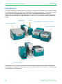
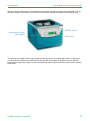
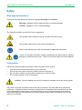
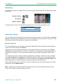
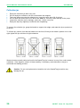
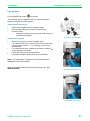
The miVac Modular Concentrator Series User Manual Original instructions Part number 04-5057 Issue 3-2 July 2014 Contents Introduction.................................................. 2 Safety............................................................ 4 Warnings and cautions ................................... 4 Precautions ..................................................... 4 Combustible solvents ..................................... 5 Electrical earthing ........................................... 5 Strong acids .................................................... 5 Limitations of use ............................................ 5 Options ......................................................... 6 Duo concentrator ............................................ 6 Quattro concentrator....................................... 6 SpeedTrap™ .................................................. 6 Duo / Quattro pump ........................................ 6 Super vacuum pump ...................................... 7 Pressure controller ......................................... 7 Lyo-option ....................................................... 7 DNA concentrator ........................................... 7 Rotors ............................................................. 8 Vapour trap ..................................................... 8 Two litre jar for SpeedTrap ............................. 8 Accessories .................................................... 9 Concentrator - Basic Operation ................ 10 Power up....................................................... 10 Standby mode .............................................. 10 Opening the lid ............................................. 10 Controls ........................................................ 11 LCD screen ................................................... 12 Getting started .............................................. 13 Selecting a method ....................................... 14 Starting the concentrator .............................. 15 Evaporation in progress................................ 15 Stopping the concentrator ............................ 15 Concentrator - Advanced Operation ........ 16 Method choice .............................................. 16 Setting chamber temperature ....................... 17 Pre-heat ........................................................ 18 Latching pre-heat .......................................... 18 Setting total time ........................................... 19 Setting heat time........................................... 20 Display mode ................................................ 21 SpeedTrap™ ............................................... 24 Waste solvent .............................................. 24 Defrosting..................................................... 25 Automatic defrost ......................................... 25 Manual defrost ............................................. 25 Collection jar ................................................ 26 Lyo-option .................................................... 27 Method Guide ............................................. 28 Pre-programmed methods ........................... 28 SpeedTrap™ ............................................... 28 Acceptable solvents ..................................... 29 Maintenance ............................................... 30 Recommended practice ............................... 30 Cleaning ....................................................... 30 Concentrator lid seal .................................... 31 Spindle friction washer ................................. 32 SpeedTrap jar seal ...................................... 33 Unpacking and Setting Up......................... 34 Modular systems .......................................... 34 miVac connection kit .................................... 34 Fitting the catch-pot ..................................... 34 Installation site ............................................. 35 Mains frequency (Japan only)...................... 35 DNA ............................................................. 36 Concentrator and pump ............................... 37 Concentrator, SpeedTrap and pump ........... 38 Concentrator, SpeedTrap and SVP ............. 39 Lyo-option .................................................... 41 Setting-up..................................................... 41 Stand-alone SpeedTrap............................... 44 Stand-alone pump ....................................... 44 Vapour trap .................................................. 45 Pressure controller ....................................... 45 Final checks ................................................. 46 Troubleshooting......................................... 47 Faults and errors .......................................... 47 Rectifying faults and errors .......................... 47 Clearing faults and errors ............................ 48 Opening lid without power ........................... 48 Other troubleshooting .................................. 49 Loading Samples into Concentrator ........ 22 Technical Data............................................ 51 Preparation ................................................... 22 Loading ......................................................... 23 Final checks .................................................. 23 Specifications ............................................... 51 EC declaration of conformity........................ 53 Warranty statement ..................................... 53 Consumable items ....................................... 54 Patents ......................................................... 55 Amendment control ...................................... 56 Useful information ........................................ 58 miVac Modular Concentrator Series User Manual Introduction The miVac modular concentrator series is a range of units that can be combined in a number of ways to provide great flexibility for a variety of centrifugal concentrator applications. Concentrators feature built in methods for alcohol and for water, they come in two different sizes and an optional SpeedTrap™ can be added to dramatically improve performance; a pressure controller can also be added to further enhance the system’s flexibility. A choice of oil free vacuum pumps completes the system. SpeedTrap Quattro concentrator Pump DNA combined concentrator and pump Duo concentrator Pressure controller Components from the miVac range may be used with similar equipment from other manufacturers. All equipment is designed for ease of use, offers very high performance and takes up a small amount of bench space in the laboratory. 2 04-5057 Issue 3-2 July 2014 User Manual miVac Modular Concentrator Series Set-up is simple with just one set and select control and a minimum number of push button controls. When the system is operating, an LCD screen shows the sample temperature and elapsed time. SELECT control Push buttons for stop, start, preheat LCD screen This manual will explain the set-up process and show you how to operate the system. It will guide you through the maintenance requirements and provide information to facilitate the most efficient procedure to protect the integrity of your samples and ensure optimum performance from the system at all times. 04-5057 Issue 3-2 July 2014 3 miVac Modular Concentrator Series User Manual Safety Warnings and cautions This symbol is used within this manual to highlight warnings and cautions. Warning: highlights a risk of personal injury or material damage. Caution: highlights a risk of material damage. The following symbols may be found on the equipment: This symbol means surfaces may be hot and could cause burns. This symbol means there is risk of hand entrapment. Refer to the relevant part of the User Manual for additional information. These Two symbols combined, indicate hazards that can lead to serious material damage or potential serious injury. Refer to the relevant part of the User Manual. Precautions Observe the following safety precautions when using the miVac system: Only use rotors that are approved for use by Genevac Do not leave the system unevenly loaded, someone may start it Do not start or restart a system without checking it is evenly loaded Do not place objects on top of the system. Caution: Incorrect loading may result in damage to samples and to the miVac system. Only allow users who are familiar with all the issues outlined in this User Manual to operate the equipment. If personnel lack the training or experience to comprehend the hazards that can arise when operating the miVac system, do not allow them to use it; personnel without such training require thorough instruction and the instructions contained within this User Manual may form the basis of such training. 4 04-5057 Issue 3-2 July 2014 User Manual miVac Modular Concentrator Series Combustible solvents Warning: Risk of vapour ignition. Only operate the miVac system in a well-ventilated environment and consider safety when evaporating any combustible solvents. Genevac's position regarding the evaporation of such solvents, particularly with respect to the European ATEX directive, is available on our website, at www.genevac.com, or from your local Genevac distributor. Electrical earthing Warning: Risk of electric shock. This equipment must be earthed. The evaporation system is a safety class I product according to IEC classification. It must never be used with any interruption to the safety earth conductor. For systems with multiple power leads, each lead requires a separate earth connection and must be plugged into a separate power socket which is connected directly into the laboratory electrical supply; do not use extension leads. This equipment is an installation class II product and is intended to operate from a normal singlephase supply. Strong acids Caution: The miVac concentrator is unsuitable for use with strong acids. Do not attempt to evaporate strong acids such as HCl, TFA or HBr, at any concentrations. Limitations of use Caution: Rotary-vane oil-filled vacuum pumps are not recommended for use with miVac systems. Vapours from the system may cause damage to the pump. Notwithstanding the above advice, if a rotary vane oil pump is used, the pump should be run with the gas ballast set to position 1; this will help to prevent damage to the pump. Oil pumps should then be run for one hour after the end of the concentration process (with ballast still engaged) to ensure that there is no condensed vapour in the pump. Ultimately, it is the responsibility of the user to check with the pump manufacturer as to how the pump should be operated. 04-5057 Issue 3-2 July 2014 5 miVac Modular Concentrator Series User Manual Options Items shown in this section can be combined in numerous ways to form the basis of a miVac concentration system. The DNA concentrator is an exception; it offers the option to purchase a complete stand-alone system. Duo concentrator The Duo concentrator is designed to accept a two swing position microplate holder, or a range of disc rotors for tubes or vials. Quattro concentrator The larger Quattro concentrator can accommodate a four swing position rotor, larger capacity disc rotors and can also accept Duo rotors. SpeedTrap™ SpeedTrap (condenser) can improve the performance of any miVac system by removing large volumes of vapour and condensing them to liquid. The effect is a dramatic improvement in the system’s ability to maintain vacuum and is reflected in reduced concentration times. Duo / Quattro pump A choice of either Duo (< 10 mbar) or Quattro (< 3 mbar) diaphragm pump can be selected to complement either Duo or Quattro concentrator. Both pumps offer oil free, low maintenance operation. 6 04-5057 Issue 3-2 July 2014 User Manual miVac Modular Concentrator Series Super vacuum pump For exceptionally demanding applications, a super vacuum (0.15 mbar) scroll pump can be selected. This pump offers oil free, low maintenance operation. Pressure controller For enhanced performance, a pressure controller can be added to any modular miVac system. The device can automatically sense the control pressure for any solvent, or can provide vacuum ramping to reduce the risk of bumping. Lyo-option A Lyo-option can be added to any modular miVac system that features a SpeedTrap with switchable defrost mode (manufactured from March 2011) and must be installed in conjunction with a super vacuum pump. The miVac Lyooption includes: vacuum isolation valve and mounting bracket cascade condenser pot three quick seal valves three insulated vial holders. Additional accessories can be ordered individually. DNA concentrator The DNA concentrator offers an alternative to modular units, combining a Duo concentrator and Duo pump into an integrated unit. The DNA is capable of removing small volumes of water and organic solvents; the unit is extremely compact and will easily fit on a bench top. There is no option to add a SpeedTrap. 04-5057 Issue 3-2 July 2014 7 miVac Modular Concentrator Series User Manual Rotors A full range of rotors is available for the miVac range, including: open sample holders solid aluminium JetRotors swing rotors for microtitre plates. Your local miVac distributor will be happy to offer advice or information on the full range of miVac rotors available. Vapour trap For neutralising ammonia or acid vapours on systems with Duo or Quattro pumps, the vapour trap replaces the pump exhaust catch-pot and comes complete with all connectors required to fit it to the system. Order using Genevac part number: VAP-TRAP0-100 Note: Requires neutralising solution, see: Accessories. Two litre jar for SpeedTrap Larger capacity jar replaces one litre jar supplied with SpeedTrap. 8 04-5057 Issue 3-2 July 2014 User Manual miVac Modular Concentrator Series Accessories Part number STJ-10000-000 STJ-20000-000 MCK-00000-Y00 RTR-FRCTN-001 MCK-EXTN1-000 04-5016 AB7210 VAP-TRAP0-100 NH3-REF00-100 ACD-REF00-100 FDA-IMP00-000 Description 1 litre jar for miVac SpeedTrap 2 litre jar for miVac SpeedTrap miVac connection kit for connecting pump and / or SpeedTrap trap to concentrator. Comes complete with two vacuum hoses (length 1 m and 1.5 m), pump control cable and pump catch-pot assembly. Spindle friction washer (prevents rotor slippage during spin-up / spin-down). Vacuum hose extension, length one metre. Exhaust hose (specify length when ordering). Clip for vacuum hose. Vapour trap (requires neutralising solution). Neutralising solution for ammonia, 4 x 500 ml Citric acid 10M solution – changes colour from green to violet. Neutralising solution for acid, 4 x 500 ml Sodium hydroxide 2 mol/l (2N) solution – changes from colourless to pink. Freeze drying accessory kit (lyo-option) requires super vacuum pump and SpeedTrap with switchable defrost mode. 04-5057 Issue 3-2 July 2014 9 miVac Modular Concentrator Series User Manual Concentrator - Basic Operation Before powering up, the concentrator must be set-up in accordance with instructions in the section: Unpacking and Setting-up. Find the description that most closely resembles the system you have and follow the appropriate set-up instructions. Operation of the controls is the same for Duo, Quattro and DNA concentrators. Power up The concentrator powers up as soon as it is connected to mains power. All segments of the LCD screen temporarily switch on and illuminate to test they are functioning correctly. When the display reverts to showing the current settings, the system is ready to be used. The vacuum pump remains in standby mode until the system is started, refer to: Starting the concentrator. For systems with a SpeedTrap, a power switch on the back allows the SpeedTrap to be switched off while it remains connected to mains power. Standby mode When the system is idle (powered-up but not operating) press the STOP button to enter standby mode. SpeedTrap power switch Press any button to restart the system. Opening the lid The concentrator automatically locks the lid to prevent it being opened when the rotor is spinning, the lid unlocks only when it is safe to open. To open the lid, manually lift the front edge and raise it to the fully open position. For Quattro concentrators, the lid latches in the fully open position. To close, lift again top release the latch, then lower the lid. Warning: Risk of hand entrapment. Lift the lid to the fully open position and make sure it is secure before placing hands near the concentrator. 10 04-5057 Issue 3-2 July 2014 User Manual miVac Modular Concentrator Series Controls On the front panel are four push buttons, a rotary SELECT control and an LCD screen. 1 2 5 3 6 4 1. MANUAL : Press once to start the system in manual mode. The concentrator emits a single beep as it starts; it continues to operate until the STOP button is pressed. Whilst operating in manual mode the respective LED lights up and a timer counts up to show the total time elapsed since starting. 2. PRE-HEAT: Press once to pre-heat the chamber to the control temperature, PRE-HEAT is disabled when either the MANUAL or AUTO button is pressed. Alternatively, press and hold for five seconds to latch-on chamber heater continually. 3. STOP ■: Press once to stop the system, the concentrator emits a single beep and stops. The STOP button can be pressed at any time, the system will shut down safely. If the STOP button is pressed when the system is idle, it will enter standby mode. Press any button to bring the system out of standby. 4. AUTO : Press once to start the system in auto mode. The concentrator emits a single beep and starts; it continues to operate until the TOTAL time set has elapsed. Whilst operating in this mode, the respective LED lights up and the timer counts down to show the time remaining. 5. SELECT: Turn the control to select a parameter (frame it with brackets) then press it to select (brackets flash to indicate adjustment mode). Ti increment a setting up or down, turn the control and then press to enter the new value. After 30 seconds without input, the display reverts back to normal mode. 6. Display: LCD screen with backlight. 04-5057 Issue 3-2 July 2014 11 miVac Modular Concentrator Series User Manual LCD screen The LCD screen provides numeric information for setting control parameters and monitoring evaporation progress. 1 3 2 4 1. Method indicator: H20 (water) -OH (alcohol) or --- (full vacuum) 2. Temperature: Chamber temperature 3. Timing mode: TOTAL time from start, or HEAT time 4. Timer: Time elapsed (in manual mode) or time remaining (in auto mode) 5 5. Adjustment mode: Brackets appear around parameter to indicate it can be adjusted using the SELECT control 6 6. 12 Error: The LCD screen also advises of any problems that occur during operation or with the settings being entered. 04-5057 Issue 3-2 July 2014 User Manual miVac Modular Concentrator Series Getting started The following is a quick reference guide only; detailed operating instructions and descriptions of features are provided later in this user manual. 1. Switch on the power at the mains supply. 2. If pre-heat is required, use the SELECT control to set the pre-heat temperature, then press the PRE-HEAT button. 3. Open the lid (for Quattro concentrators, make sure the latch engages). 4. Fit the rotor by lowering it on to the shaft. 5. Load the rotor with samples; make sure the rotor is evenly balanced. 6. Close the lid (for Quattro concentrators: lift the lid to disengage the latch). 7. Using the SELECT control: Set the chamber temperature Set the method type Set the total run time Set the heat time. Note: the last entered settings will be used if new settings are not entered. 8. Press the MANUAL or AUTO button to start the concentrator. 04-5057 Issue 3-2 July 2014 13 miVac Modular Concentrator Series User Manual Selecting a method To select the required method, turn the SELECT control until brackets appear around the method indicator. Press the SELECT control, the brackets begin to flash to indicate the parameter may be adjusted. Turn the control until the required method is shown, then press to select. The LCD display shows the selected method. 14 04-5057 Issue 3-2 July 2014 User Manual miVac Modular Concentrator Series Starting the concentrator The concentrator can be started in either manual mode or auto mode. Select the required method and set the temperature before starting the concentrator. Manual mode To start in manual mode, press the MANUAL ► button. The concentrator emits a single beep to confirm acceptance of the command and the rotor begins to spin (if the lid is not closed, a double beep sounds and the concentrator will not start). The LED adjacent to the MANUAL ► button lights up to indicate the system is operating in manual mode. Once a safe rotor speed is reached, the system begins to apply vacuum and the timer starts to count up, indicating the time accumulated. The concentrator continues until the STOP button is pressed. Auto mode To start in auto mode, press the AUTO ► button. The concentrator emits a single beep to confirm acceptance of the command and the rotor begins to spin (if the lid is not closed, a double beep sounds and the concentrator will not start). The LED adjacent to the AUTO ► button lights up to show the system is operating in auto mode. Once a safe rotor speed is reached, the system begins to apply vacuum and the timer starts to count down from the set time, indicating the time remaining. The concentrator stops when the timer reaches zero or if the STOP button is pressed. Evaporation in progress While the evaporation is in progress, the LCD screen shows the elapsed time when operating in manual mode, or the time remaining when operating in auto mode. When the time displayed is greater than one hour, it is shown in hours and minutes (HH:MM) when the time displayed is less than one hour, it is shown in minutes and seconds (MM:SS). Stopping the concentrator To stop the concentrator, press the STOP button, the concentrator emits a single beep to acknowledge acceptance of the command. The STOP button can be pressed at any time, the system will always stop safely. When operating in auto mode, the concentrator stops automatically when the timer reaches zero. The STOP button can also be used to stop the system when it is operating in auto mode. The auto or manual LED flashes to indicate the system is stopping, four longer beeps sound when the rotor is about to stop. The time remains on the LCD screen until the lid is opened. 04-5057 Issue 3-2 July 2014 15 miVac Modular Concentrator Series User Manual Concentrator - Advanced Operation Method parameters can be adjusted at any time, including when the concentrator is operating. To adjust a method parameter: Turn the SELECT control - brackets appear around different areas of the LCD display. Press the SELECT control – the brackets begin to flash. Turn the SELECT control – the selected value increments up or down. Press the SELECT control – the new value is entered. Note: If the SELECT control is not pressed, the displayed value is automatically entered after 30 seconds. Method choice There are three methods to choose from: H2O -OH --- for water only for alcohols and alcohol mixtures for all other solvents. For further information, refer to Method Guide. 16 04-5057 Issue 3-2 July 2014 User Manual miVac Modular Concentrator Series Setting chamber temperature The chamber temperature can be controlled from 30°C to 80°C by 1°C increments. If the temperature is set below 30°C, the display shows [--°C] and the chamber heater is turned off. Once the new value is selected, the display reverts back to showing the current chamber temperature (in the following example, the current chamber temperature is 24°C). Select parameter. Adjust the value to the required chamber temperature. The LCD display reverts to showing the current chamber temperature. 04-5057 Issue 3-2 July 2014 17 miVac Modular Concentrator Series User Manual Pre-heat For solvents with a boiling point greater than 90°C, the chamber should be pre-heated to avoid solvent condensation in the evaporation chamber. Prolonged exposure to certain solvents in liquid form may cause damage to the concentrator lid coating. To pre-heat the concentrator, press the PRE-HEAT button. An LED adjacent to the PRE-HEAT button lights up to show the chamber heater is active, and the chamber warms up to the currently set control temperature. For best results, place the empty rotor in the concentrator and leave the concentrator lid closed while pre-heating. Caution: Bumping may occur if the sample temperature is too high when the concentrator is started. To avoid the possibility of damage to samples, do not pre-heat the concentrator with samples loaded. Once the concentrator is started (by pressing either the MANUAL ► or AUTO ►start buttons) the chamber remains at the control temperature until the heat time elapses; the chamber heater then switches off. Latching pre-heat Pre-heat can be “latched” to stay on continually throughout the evaporation process and after the concentrator stops. This function allows the chamber to be kept warm, ready for the next use. To latch on pre-heat, press and hold the PRE-HEAT button for five seconds. A confirmation beep sounds to acknowledge acceptance of the command, the chamber warms up to the control temperature and the heater continues to control the chamber at the control temperature throughout the evaporation process and after the system stops, even if the STOP button is pressed. To cancel the function, press the PRE-HEAT button again. Note: For older systems (software versions pre V1.09) the chamber preheats to 40°C, irrespective of the chamber control temperature. 18 04-5057 Issue 3-2 July 2014 User Manual miVac Modular Concentrator Series Setting total time This feature allows the user to set the total time duration of the evaporation process when using auto mode. Select the timer. Set the time required. The LCD display counts down the time remaining. Note: The maximum permissible time setting is 99 hours and 59 minutes (99:59). 04-5057 Issue 3-2 July 2014 19 miVac Modular Concentrator Series User Manual Setting heat time This feature controls the time duration that chamber heating is applied. Note: The heat time: cannot be longer than the TOTAL time has no effect if PRE-HEAT is latched on. Select the timer. Select HEAT. Set the heat time. The LCD display counts down the heat time remaining. 20 04-5057 Issue 3-2 July 2014 User Manual miVac Modular Concentrator Series Display mode The LCD display is factory set to show TOTAL time. But it can be changed to show HEAT time when operating in auto mode. To change the display mode, hold down the SELECT control for five seconds; a single beep sounds to acknowledge acceptance of the command. The display changes to indicate HEAT until the countdown reaches zero, then reverts to showing the TOTAL time remaining. To change the display mode back from HEAT time to TOTAL time, hold down the SELECT control again for five seconds. 04-5057 Issue 3-2 July 2014 21 miVac Modular Concentrator Series User Manual Loading Samples into Concentrator Samples in the concentrator chamber are subjected to accelerations of up to 250 g (250 times greater than the force of gravity). It is therefore important for the operator to understand the safety requirements and to gain familiarity with the safe loading procedure outlined below. Preparation To reduce concentration time, the system can be pre-heated before use. If rapid concentration is important, leave the empty rotor in the concentrator with the lid shut and pre-heat enabled; short evaporation runs in particular will benefit from this. Refer to Pre-heat for further details. Caution: To avoid damage to samples, do not pre-heat with the samples loaded. The following graph shows the typical reduction in concentration time that can be achieved, firstly by using a SpeedTrap, and then by pre-heating both chamber and rotor. 22 04-5057 Issue 3-2 July 2014 User Manual miVac Modular Concentrator Series Loading Balance the rotor within 10 g. Only load tubes or vials into the rotors that are specified on the rotor. For the Duo, two position swing rotor, use a maximum of three shallow well microplates (with stackers) or one deep-well microplate per rotor location. For the Quattro, four position rotor, use a maximum of five shallow well microplates (with stackers) or two deep-well microplates per rotor location. Only fill tubes, vials or wells of microplates etc, to 66% of their maximum fill level. When using swing rotors, always load opposite swings with the same or similar type of plates. Do not exceed the maximum safe loading weight of 0.6 kg per swing for Duo swing rotors, and 1.1 kg per swing for Quattro swing rotors. Final checks Make sure tubes / vials are located correctly in the rotor. For swing rotors, rotate a swing rotor by hand after loading to check that all plates are correctly located before starting a run and before re-starting an interrupted run. 04-5057 Issue 3-2 July 2014 23 miVac Modular Concentrator Series User Manual SpeedTrap™ The miVac SpeedTrap offers: Unique frost free cold-trap Selectable automatic defrosting, all solvents (including water) collect as liquids Easy to empty collection jar. Caution: Refer to list of acceptable solvents before use. A power switch on the back of the SpeedTrap allows it to be powered down while remaining connected to mains power (unlike the miVac concentrator which powers up as soon as power is connected). Power switch Waste solvent Waste solvents normally collect as liquid in the SpeedTrap jar; however ice may form under certain conditions. Refer to Collection Jar for further information. Occasional sudden boiling within the jar is normal and solvent will re-condense. 24 04-5057 Issue 3-2 July 2014 User Manual miVac Modular Concentrator Series Defrosting The defrosting mode of the SpeedTrap can be set using the switch located on the SpeedTrap splashback panel. Periodic defrost No defrost Manual defrost The green LED on front of the SpeedTrap indicates the current state of the defrost cycle. LED Fast flash Slow flash Steady Condition Defrosting Chilling Condensing Automatic defrost For fully automatic defrosting without the need for intervention by the user, set the switch to periodic defrost. Defrosting of the condenser coil occurs automatically for three minutes in every hour. After defrosting, the SpeedTrap switches to chilling, then condensing. Manual defrost For some applications it is preferable to operate the SpeedTrap continually without periodic defrost. In this case, set the switch to no defrost. A defrost cycle may be initiated manually by momentarily pushing the switch down to the manual defrost position (the switch does not “latch” in this position). The defrost cycle takes approximately 30 minutes to complete, or can be cancelled manually by momentarily pressing the switch down again. The defrost mode may be switched while the SpeedTrap is operating. When the mode is switched from periodic defrost to no defrost, the SpeedTrap performs a short (three minute) defrost before continuing to operate in no defrost mode. When switched from no defrost to periodic defrost, the SpeedTrap chills for 57 minutes before performing a short (three minute) defrost. When choosing which mode of operation to select, consider the solvent being condensed; for further information, refer to Method Guide. Note: SpeedTraps manufactured before February 2010, do not have switchable defrost modes. These units operate in periodic defrost mode only. 04-5057 Issue 3-2 July 2014 25 miVac Modular Concentrator Series User Manual Collection jar Empty the collection jar after every use Do not empty the collection until the concentrator has stopped Take care when removing the collection jar, it may be heavy when full of solvent Do not allow the solvent level to fill above the max line, this may cause damage to the pump Inspect the collection jar for damage, cracks etc., before every use Empty the drip tray regularly to avoid the risk of splashing. To remove the collection jar, grasp the handle to support the weight, and rotate the jar a quarter turn to the left. To refit the jar, position it so that the handle is to the front, lift the jar and rotate a quarter turn to the right; tighten the jar until there is light resistance. Waste solvents normally collect as liquid in the SpeedTrap jar, however ice may form under certain conditions. If this happens, allow it to thaw naturally; if necessary, add cold water to the jar to accelerate the thawing process. Caution: Do not use implements to break the ice in the SpeedTrap jar as this may damage the jar. 26 04-5057 Issue 3-2 July 2014 User Manual miVac Modular Concentrator Series Lyo-option On the SpeedTrap, select: , no defrost. The isolation valve (supplied in the Lyo-option kit) allows flexible configuration of the system: Stand-alone freeze dryer Close the lyo-option vacuum isolation valve Remove the collection jar from the SpeedTrap Connect either o cascade condenser pot (with quick seal valves), or o insulated vial holders. Combination system Lyo-option accessories Open the lyo-option vacuum isolation valve For systems that have a control valve fitted to the super vacuum pump, select “---“ (no venting) on the miVac concentrator For systems that have a pressure controller, select P MIN on the pressure controller. Fit the collection jar to the SpeedTrap Lyophilise samples directly from the concentrator. Note: For lyophilisation, samples must be frozen before loading into the miVac system. After lyophilisation, defrost the SpeedTrap manually. See Manual defrost. Cascade condenser pot Insulated vial holders 04-5057 Issue 3-2 July 2014 27 miVac Modular Concentrator Series User Manual Method Guide Pre-programmed methods The Quattro, Duo and DNA concentrators have three pre-programmed methods which control the rate of air venting into the evaporation chamber in order to optimise evaporation conditions for the solvent. Method H2O -OH --- Venting rate Low High No venting When to use For water only For alcohols and alcohol mixtures For all other solvents The -OH and H2O methods also turn the pump off periodically to aid the flow of energy into the samples. For Duo and Quattro concentrators, the H2O method is optimised for aluminium rotors. This method is recommended when evaporating more than a few tubes of water; however full vacuum --- may be faster if there are just a few tubes. For DNA systems, use the H2O method when evaporating water or solvents with similar boiling points. Alternatively, the performance of any miVac modular system can be enhanced with the addition of a pressure controller which allows automated pressure control and vacuum ramping. If a pressure controller is used, the miVac concentrator must be set to “---“ (no venting). SpeedTrap™ The SpeedTrap mode can be set to optimise conditions for the solvent: Switch position 28 SpeedTrap Mode When to use Periodic defrost For water or water mixtures No defrost For organic solvents that will not freeze For lyo-option 04-5057 Issue 3-2 July 2014 User Manual miVac Modular Concentrator Series Acceptable solvents Carry out a risk assessment for each solvent or solvent mixture before use. The common solvents included in the following table are not damaging to the evaporator providing appropriate methods are used. Contact your local Genevac representative for advice before using solvents which are not listed. Solvent Abbreviation Acetic acid MeCO2H Acetonitrile MeCN, ACN Ammonium Hydroxide NH3OH 1-Butanol Butyl acetate Chloroform CHCl3 1,2-Dichloroethane DCE Dichloromethane DCM 1,4-Dioxane Ethanol EtOH Ethyl Acetate EtOAc Formic Acid HC02H Heptane Hexane Methanol MeOH Methyl tertiary butyl ether MTBE 1-Propanol 2-Propanal IPA Sodium hydroxide NaOH Tetrahydrofuran THF Toluene Water H2O ■ □ 04-5057 Issue 3-2 July 2014 Recommended method ---OH H2O -----OH -OH -OH --H2O or -OH -OH -----OH H2O or -OH -OH -OH -OH --- or H20 -OH --- or H2O H2O SpeedTrap mode DUP QUP SVP ■ ■ ■ ■ ■ ■ ■ ■ ■ ■ ■ □ □ ■ ■ ■ □ □ □ ■ ■ ■ □ □ □ ■ ■ ■ □ □ □ □ □ □ □ □ □ ■ ■ ■ ■ ■ ■ □ □ □ ■ ■ ■ ■ ■ ■ ■ ■ ■ □ □ □ □ □ □ ■ ■ ■ Compatible Compatible with miVac modules manufactured after April 2007. 29 miVac Modular Concentrator Series User Manual Maintenance In order to provide trouble free operation, Genevac recommend the miVac pump is serviced annually. Any servicing or repair of miVac products, other than that which is specified within this User Manual, should be carried out by Genevac personnel (or approved representatives of Genevac) using only approved spare parts. Recommended practice Check before use: All hose joints are secure The SpeedTrap collection jar, empty if necessary The catch-pot is connected to the pump exhaust, empty if necessary. Cleaning 30 Clean the SpeedTrap collection jar at regular intervals o Collection jar is dishwasher safe but not suitable for an autoclave Clean the lid, lid seal, exterior paintwork and inside of the chamber with a soft, lint-free cloth, slightly dampened with: o Detergent solution o Bleach solution (if using biological agents) o Methanol o Ethanol. Do not use abrasives. 04-5057 Issue 3-2 July 2014 User Manual miVac Modular Concentrator Series Concentrator lid seal Description Lid seal - Duo Lid seal - Quattro Part number 04-4722 04-4793 Warning: Risk of contamination. Solvent traces may be present that could be harmful to health or lead to material damage. Testing 1. 2. 3. Close the lid. Select any method and start the concentrator. Make sure the pressure begins to drop (the lid seal feels tight against the chamber and cannot be opened). Note: Manually pushing down on the lid may be required to assist the new lid seal to bed in on Switch on the miVac concentrator and open the first use. If the pressure fails to drop, check the lid seal is correctly located on the vacuum the lid. chamber and repeat the test. Check for solvent traces and wipe the lid seal clean before removal. Removal 1. 2. 4. Note: The seal may absorb significant quantities of some solvents. 3. Allow the concentrator to continue for a while, checking for normal operation. Manually remove the lid seal from the chamber by carefully pulling the seal away from the chamber. Do not use tools that may damage the chamber coating. Refitting 1. 2. 3. Unpack the replacement lid seal. Position the lid seal on top of the vacuum chamber. Work the seal firmly into position using only fingers, press the seal fully home. 04-5057 Issue 3-2 July 2014 31 miVac Modular Concentrator Series User Manual Spindle friction washer The friction washer prevents rotor slippage during spin-up and spin-down. Check the condition of the washer frequently and replace it if damaged or worn. Description Friction washer Refitting 1. Place the washer over the spindle. Part number RTR-FRCTN-001 Removal Remove the damaged washer from the concentrator spindle. 2. Push down to form a conical shape at the base of the spindle. 32 04-5057 Issue 3-2 July 2014 User Manual miVac Modular Concentrator Series SpeedTrap jar seal If the SpeedTrap jar fails to seal or does not tighten when inserted and twisted a quarter turn, the seal and thread inserts should be replaced. Refitting 1. Insert the O-ring into the SpeedTrap moulding. 2. Insert one of the three retaining features of the PTFE seal into one of the three recesses in the SpeedTrap moulding and secure it in place using a thread insert and screw. Do not tighten the screw. 3. Taking care to avoid creasing or distorting the PTFE seal, fit the remaining two thread inserts. 4. Check the PTFE seal and O-ring are correctly fitted with no creases or bulges, then tighten all three screws. Parts required Description Replacement seal and thread insert kit Part number MST-SEALS-000 Removal 1. Remove the SpeedTrap jar. 2. Using the screw driver, undo the screws and remove the three thread inserts as shown. Testing 3. Remove the PTFE seal and O-ring. 04-5057 Issue 3-2 July 2014 1. Fit the SpeedTrap jar and check it jar feels tight. 2. Operate the miVac system to make sure there are no vacuum leaks, use “dummy” samples if necessary to make sure the concentrator operates correctly. 33 miVac Modular Concentrator Series User Manual Unpacking and Setting Up On delivery, please check the contents of the delivery as soon as possible against the delivery note and notify your distributor immediately if any parts are missing or damaged. Refer to our web site for up to date contact details. Modular systems Instructions for setting-up miVac modular system will vary, depending upon the combination of miVac units that has been purchased. The following instructions should be considered guidance that may be amended where combinations of units are different to those shown. miVac connection kit A miVac connection kit (Genevac part number MCK-00000-Y00) is supplied when you order a combination of miVac units (not including DNA Concentrator). In it you will find all the items required to set-up a miVac system. The system connection kit includes: Catch-pot for pump exhaust Pump control cable Exhaust hose 1.5 m (clear PVC) Vacuum hoses 1 m and 1.5 m (metal reinforced) Hose clips for vacuum hoses. Additional hoses can be ordered, see: Accessories. Fitting the catch-pot The catch-pot, supplied with the miVac connection kit, clips to the ventilation holes on the side of a miVac unit. When connecting exhaust hoses, please note the catch-pot outlet has a filter on the inside of the glass jar, the inlet is not filtered. Inlet Outlet Outlet filter 34 04-5057 Issue 3-2 July 2014 User Manual miVac Modular Concentrator Series Installation site Due to the modular design of miVac units, systems can be set-up in a number of ways; the illustrations on the following pages show the most common configurations. Specific requirements of the installation may vary from one system to another, however the following general principals apply to all installations. The miVac system must be placed on a level, sturdy work surface. There must be a 50 mm air gap between each miVac unit and the edge of the bench, wall or any other equipment. 50 mm air gap around system One, two or three mains power cables will be required, depending on the combination of miVac modules. These must be connected to separate mains power supply outlets. Unequal length vacuum hoses supplied are supplied in the miVac connection kit, these may be configured to suite the system layout. For example, using the longer hose, the pump and SpeedTrap may be positioned on a shelf below the concentrator. The exhaust hose must be connected so it takes solvent vapours safely away from the concentrator and away from the user; ideally it should be connected to a laboratory fume extraction system. Mains frequency (Japan only) Caution: If setting-up a system for use in Japan, make sure the frequency adjuster on the rear of the SpeedTrap is set to the correct frequency for the local mains power supply. 04-5057 Issue 3-2 July 2014 Frequency adjuster 35 miVac Modular Concentrator Series User Manual DNA Position the DNA concentrator in the desired location on the bench. 2 1 1. Catch-pot: Fit the catch-pot to the DNA by clipping it to the vent holes near the exhaust outlet. Cut a suitable length of exhaust hose and use it to connect the exhaust outlet to the catch-pot. 2. Exhaust hose: Using the short hose supplied, connect the exhaust outlet to the catch-pot inlet (the outlet has a filter on the inside of the glass jar). Cut a suitable length of exhaust hose and use it to connect the catch-pot outlet to the laboratory fume extraction system. 3. Power cable: Using the power cable supplied, connect the DNA to a mains power outlet. 36 04-5057 Issue 3-2 July 2014 User Manual miVac Modular Concentrator Series Concentrator and pump Requires a miVac connection kit. Position the concentrator and pump beside each other on the bench. 2 4 1 3 5 1. Catch-pot: Fit the catch-pot to the vacuum pump by clipping it to the ventilation holes on the side of the pump. 2. Exhaust hose: Cut a suitable length of exhaust hose and use it to connect the pump exhaust outlet to the catch-pot inlet. Using the remaining exhaust hose, connect the catch-pot outlet to the laboratory fume extraction system. 3. Vacuum hose: Using the vacuum hoses, connect the concentrator vacuum outlet to the SpeedTrap vacuum inlet; also connect the SpeedTrap vacuum outlet to the pump vacuum inlet. Secure the connections using the hose clips supplied. Note: Unequal length vacuum hoses are supplied; these may be configured to suite the system layout. 4. Pump control cable: Using the pump control cable, electrically connect the pump to the concentrator. 5. Power cable: Using the power cable syupplied, connect the concentrator to a mains power supply outlet. Note: Do not connect the pump directly to the mains power supply; the power cable supplied with the pump is for standalone use of the pump only. 04-5057 Issue 3-2 July 2014 37 miVac Modular Concentrator Series User Manual Concentrator, SpeedTrap and pump Requires a miVac connection kit. Position the concentrator, SpeedTrap and pump in the desired location. 2 4 1 5 3 1. Catch-pot: Fit the catch-pot to the vacuum pump by clipping it to the ventilation holes on the side of the pump. 2. Exhaust hose: Cut a suitable length of exhaust hose and use it to connect the pump exhaust outlet to the catch-pot inlet. Using the remaining exhaust hose, connect the catch-pot outlet to the laboratory fume extraction system. 3. Vacuum hose: Using the vacuum hoses, connect the concentrator vacuum outlet to the SpeedTrap vacuum inlet; also connect the SpeedTrap vacuum outlet to the pump vacuum inlet. Secure the connections using the hose clips supplied. 4. Pump control cable: Electrically connect the pump to the concentrator. Caution: After unpacking the SpeedTrap leave to stand for 24 hours before switching on. 5. Power cables: Using the power cables supplied, connect the Concentrator and SpeedTrap to two seperate mains power supply outlets. Note: Do not connect the pump directly to the mains power supply; the power cable supplied with the pump is for standalone use of the pump only. 38 04-5057 Issue 3-2 July 2014 User Manual miVac Modular Concentrator Series Concentrator, SpeedTrap and SVP Requires a miVac connection kit plus additional parts supplied with miVac super vacuum pump. Position the concentrator, SpeedTrap and super vacuum pump in the desired location on the bench. 2 1 3 1. Pump gas ballast: Set the pump gas ballast control to position 1. 2. Pump control valve: Using a KF25 ring and clamp (supplied with the SVP) fit the pump control valve to the pump vacuum inlet. 3. Exhaust hose adapter: Using a KF25 ring and clamp (supplied with the SVP) fit the exhaust hose adapter to the pump exhaust outlet. 04-5057 Issue 3-2 July 2014 39 miVac Modular Concentrator Series 4 User Manual 5 7 8 6 4. Catch pot: Fit the catch-pot to the SpeedTrap by clipping it to the ventillation holes on the side of the unit. 5. Exhaust hose: Cut a suitable length of exhaust hose and use it to connect the pump exhaust outlet to the catch-pot inlet. With the remaining exhaust hose, connect the second catch-pot spigot to the laboratory fume extraction system. 6. Vacuum hoses: Using either the 1 m or the 1.5 m vacuum hose (supplied in the connection kit) connect the concentrator vacuum outlet to the SpeedTrap vacuum inlet. Using the second vacuum hose, connect the SpeedTrap vacuum outlet to the pump vacuum inlet. Secure the connections with hose clips. 7. Pump control cable: Using the pump control cable, electrically connect the pump control valve to the concentrator. 8. Power cables: Using three power cables, connect the Concentrator, SpeedTrap and super vacuum pump to three separate mains power supply outlets. Caution: The electrical interconnecting cable is to be used for connecting between the concentrator and pump isolation valve only. Do not connect the electrical interconnecting cable to the pump power inlet. 40 04-5057 Issue 3-2 July 2014 User Manual miVac Modular Concentrator Series Lyo-option The miVac Lyo-option can be fitted to any miVac system that has a SpeedTrap with a switchable defrost mode (manufactured from March 2011 onwards) and a miVac super vacuum pump. The lyooption kit includes an isolation valve that allows the SpeedTrap to be isolated from the concentrator. Setting-up Note: If the super vacuum pump has a pump control valve fitted, remove this before fitting the Lyooption kit. 2 1 1. Pump gas ballast: Set the pump gas ballast control to position 1. 2. Hose adapters: Using KF25 centring rings and clamps, fit hose adapters to the pump vacuum inlet (top connector) and pump exhaust (side connector). 04-5057 Issue 3-2 July 2014 41 miVac Modular Concentrator Series User Manual 3 4 3. Iso-valve: Fit the iso-valve to the SpeedTrap by clipping it to the ventillatioin holes in the side of the unit and securing it in place with the screws provided. Note: Large and small screws are provided to enable the bracket to be fitted to either side of the SpeedTrap. 4. 42 Catch-pot: Fit the catch-pot to the SpeedTrap by clipping it to the ventillation holes in the side of the unit. 04-5057 Issue 3-2 July 2014 User Manual miVac Modular Concentrator Series Lay out the units of the miVac system in the desired location as shown. 5 7 6 5. Exhaust hose: Cut a suitable length of exhaust hose and use it to connect the pump exhaust (hose adapter) to the catch-pot inlet (the outlet has a filter on the inside of the glass jar). Using the remaining exhaust hose, connect the catch-pot outlet to the laboratory fume extraction system. 6. Vacuum hose: Using the vacuum hoses, connect: the concentrator vacuum outlet to the iso-valve inlet. the iso-valve outlet to the SpeedTrap vacuum inlet. the SpeedTrap vacuum outlet to the super pump vacuum pump vacuum inlet. Secure the connections using the hose clips supplied. Clip the iso valve to the mounting bracket, making sure the direction of flow (indicated by an arrow on the valve) is from concentrator to SpeedTrap. 7. Power cables: Using the power cables supplied, connect the super vacuum pump, SpeedTrap and concentrator to three separate mains power supply outlets. 04-5057 Issue 3-2 July 2014 43 miVac Modular Concentrator Series User Manual Stand-alone SpeedTrap If connecting a miVac SpeedTrap to equipment, other than a miVac modular system, connect it as shown: External vacuum source Solvent vapour in from external equipment Using the power cable supplied with the SpeedTrap, connect the SpeedTrap to the mains power supply. Stand-alone pump If connecting a miVac pump to equipment other than a miVac modular system, connect it as shown: Vacuum connection to external equipment If using a catch-pot, fit it to pump by clipping it to the cladding vent holes, on the side of the vacuum pump. Using the power cable supplied, connect the pump to the mains power supply. 44 04-5057 Issue 3-2 July 2014 User Manual miVac Modular Concentrator Series Vapour trap To install the optional vapour trap, remove the pump catch pot and replace it with the vapour trap. Connect the pump exhaust to the vapour trap top connector (inlet), connect the outlet elbow connector to the laboratory fume extraction system. Inlet - connect to pump exhaust Outlet - connect to laboratory fume extraction system Unscrew the jar and fill to the level indicator (approx. 300 ml) with the required neutralising solution. Replace the neutralising solution as required to maintain efficiency. Pressure controller To further increase the flexibility of the miVac system, a pressure controller can be connected to the vacuum line between the pump and the SpeedTrap. For details, refer to the miVac Pressure Controller User Manual. miVac pressure controller 04-5057 Issue 3-2 July 2014 45 miVac Modular Concentrator Series User Manual Final checks Carry out a safety assessment before operating the miVac system. Make sure the exhaust hose takes solvent away from personnel, and from the system, in a safe manner. If personnel lack the training or experience to comprehend the hazards that can arise when using the miVac system, do not allow them to use it. Personnel without such training require thorough instruction. The instructions contained within this User Manual may form the basis of such training. Maintain a solvent vapour free environment around the miVac system. Do not use the free space around the system for the storage of vessels containing solvents or acids. This instruction applies, even if the miVac system is installed in a fume cupboard. Caution: After setting up, leave the SpeedTrap in the upright position for 24 hours before switching on. 46 04-5057 Issue 3-2 July 2014 User Manual miVac Modular Concentrator Series Troubleshooting Faults and errors If the miVac system detects a problem; an error number is shown on the LCD display. When errors occur during operation, the error number is shown when the system stops. Rectifying faults and errors Err code Cause of error 01 Software error – memory failure 02 Lid not closed during run 03 Lid not locked during run 04 Motor drive error 05 Rotor failed to spin 06 Rotor failed to reach speed 07 Rotor stops unexpectedly 08 Lid failed to lock 09 Lid failed to unlock 10 Software error – sensor read error 11 Software error – chamber temperature low 12 Software error – chamber temperature high 04-5057 Issue 3-2 July 2014 Rectification Clear error and attempt to restart Make sure lid is closed and engaged with latch Check lid seal is fully seated Make sure lid is closed and engaged with latch Check lid seal is fully seated Clear error and attempt to restart Manually rotate rotor approximately 45° and restart Make sure rotor spins freely Check mains power supply within tolerance Make sure rotor spins freely Check mains power supply within tolerance Make sure lid is closed and engaged with latch Check lid seal is fully seated Make sure lid is closed and engaged with latch Make sure user not lifting lid against latch Check lid seal is fully seated Clear error and attempt to restart Clear error and attempt to restart Clear error and attempt to restart 47 miVac Modular Concentrator Series User Manual Clearing faults and errors To clear an error, press and hold the STOP button for five seconds. Alternatively, switch the system power off, wait five seconds and then switch the power back on again. If the problem is still apparent, contact your distributor or Genevac Service. Opening lid without power In the event of a power supply failure, the lid can be unlocked manually to gain access to samples. Insert a narrow tool through the hole in the cladding (above the top left hand side screw) and use it to press on the lid lock actuator to release the lid lock mechanism, simultaneously open the lid. For emergency lid release without mains power, Insert tool through hole Note: The lid will be locked if closed when power is not connected to the concentrator. Warning: Risk of injury, make sure the rotor is stationary and the system has vented to atmospheric pressure before opening the lid. Wait at least two minutes following a power failure before opening the lid. 48 04-5057 Issue 3-2 July 2014 User Manual miVac Modular Concentrator Series Other troubleshooting Symptom Display blank Lid will not open / difficult to open Cause No power Dirty lid seal Rotor will not spin double beep Lid not fully closed Rotor will not stop Excessive vibration / noise Chamber fails to reach programmed temperature Solvent splashes / condensation inside vacuum chamber Vacuum problems Rotor jammed Rotor spindle greasy or slippery, rotor continues to spin after spindle stops Rotor imbalanced Rotor slipping Missing exhaust silencer / muffler Uneven work surface Heat time not set or insufficient SpeedTrap not operating correctly Poor vacuum Overfull plates Concentrator vacuum chamber too cold Pump not running Lid seal leaks Hoses Control valve (if fitted) not opening Condenser jar not sealed Pump inefficient Exhaust silencer / muffler blocked SpeedTrap jar seal leaking Excessive concentration times Excessive solvent in pump Condenser jar full Pump needs servicing Poor vacuum SpeedTrap not operating correctly Insufficient chamber heat SpeedTrap not operating correctly Incorrect run settings 04-5057 Issue 3-2 July 2014 Corrective action Check power supply / lead Clean lid and seal External control valve (if fitted) wrong way round Open and close lid Check lid seal fully seated Check for obstructions Check for freedom of rotor Clean / degrease rotor and spindle. Fit spindle friction washer (or replace if defective). Check and rebalance rotor Clean / degrease rotor and spindle, fit spindle friction washer Replace exhaust silencer / muffler Take corrective action Adjust See SpeedTrap See Maintenance See Loading Samples Pre-heat before use Check connections / mains power supply Check for damage / dirt. Clean if required Check for leaks Check for blockages Check connections Check connected to concentrator pump outlet Check vapour flow direction Remove jar and check seal for damage / debris Replace seal, see Maintenance Run system without samples for five minutes. Repeat three times then reload samples Replace exhaust silencer / muffler See Maintenance: SpeedTrap jar seal Empty jar Contact your distributor See Maintenance See SpeedTrap Adjust Heat time See SpeedTrap Select run settings suitable for your solvent 49 miVac Modular Concentrator Series User Manual Other troubleshooting – continued Symptom miVac pump runs continuously Excessive sample odour Cause Connected directly to mains power Solvent vapour exhausting in to lab No SpeedTrap LED illumination Excessive boiling of solvent in SpeedTrap jar No solvent in SpeedTrap jar No mains supply Warm solvent Excessive vacuum Incorrect run type Poor cooling Poor solvent recovery Excessive vacuum Incorrect run type Poor cooling 50 Corrective action Connect to concentrator using interconnecting lead Check connections Check pump / system exhaust ducted to suitable fume extraction point Check SpeedTrap mains power supply lead Stop run and empty jar, restart run Check vacuum appropriate to application Select suitable run type Allow SpeedTrap to cool for 30 minutes with no concentration, then Restart run Check LED status Check air flow, ensure vents are clear from obstruction Check vacuum appropriate to application Select suitable run type Allow SpeedTrap to cool for 30 minutes with no concentration, then restart run Check LED status Check air flow, ensure vents are clear from obstruction 04-5057 Issue 3-2 July 2014 User Manual miVac Modular Concentrator Series Technical Data Specifications DNA concentrator Max rotor speed 1465 rpm Sample acceleration 250 G Drive system Permanent magnet electronic Dimensions (w x d x h) 360 x 602 x 300 mm Catch-pot Add 141 mm to width Weight 41.5 kg Duo Concentrator Max rotor speed 1465 rpm Max sample acceleration 250 G Drive system Permanent magnet electronic Dimensions (w x d x h) 360 x 424 x 300 mm Weight 21 kg Duo Concentrator Duo Concentrator Quattro concentrator Max rotor speed 1130 rpm Max sample acceleration 250 G Drive system Permanent magnet electronic Dimensions (w x d x h) 480 x 594 x 300 mm Weight 35 kg SpeedTrap Type Single stage vapour compression Refrigerant R404a Nominal operating temperature -35°C Lowest possible temperature -50°C Maximum defrost temperature +60°C Rapid defrost Yes Rapid defrost over-ride Yes (after Feb 2011) Jar Plastic coated borosilicate glass Jar capacity 1 litre (optional 2 litres) Dimensions ( w x d x h) 212 x 563 x 450 mm Weight 25.8 kg Duo pump Ultimate vacuum < 10.0 mbar (7.5 torr) Flow rate 38 litres per minute Dimensions (w x d x h) 215 x 389 x 300 mm Weight 19 kg Duo pump Duo pump Quattro pump Ultimate vacuum < 3.0 mbar (1.5 torr) Flow rate 33 litres per minute Dimensions (w x d x h) 215 x 389 x 300 mm Weight 18 kg Quattro pump Quattro pump Super vacuum pump Ultimate vacuum 0.05 mbar Dimensions (w x d x h) 282 x 432 x 302 mm Weight 26.6 kg Super vacuum pump Super vacuum pump Storage / transportation environment Ambient temperature 0°C to 40°C (-10°C permissible during transportation) Relative humidity 0 to 95% non-condensing Altitude Sea level to 12000 m Operating environment Ambient temperature 0°C to 30 °C Relative humidity 0 to 95% Altitude Seal level to 1600 m Ingress protection rating IP30 Note: This evaporator is designed for use in a pollution degree 2 environment (normally only non-conductive pollution occurs). Emissions Noise level is typically 70 dB (A) at one metre from the concentrator during normal operation. For the purpose of air conditioning requirement calculations, it can be assumed that all power is dissipated as heat Note: Dimensions include allowances for pipe connections and for lid opening; figures quoted for weights are for guidance only (actual weights vary with build options such as mains input voltage). 04-5057 Issue 3-2 July 2014 51 miVac Modular Concentrator Series User Manual Electrical Voltage (V) 100 100 120 230 220 Freq (Hz) 50 60 60 50 60 DUP & DUC Peak Norm 500 360 490 350 590 390 590 380 520 340 Power VA (W) DUP & QUC MST Peak Norm Peak Norm 630 370 605 570 660 400 535 500 850 470 495 441 890 450 435 429 800 430 495 441 Key DUP QUP SVP DUC QUC MST DUP 250 250 250 250 250 QUP 150 150 150 150 150 SVP Peak Norm 510 400 480 380 600 470 580 390 590 440 Duo pump Quattro pump Super vacuum pump Duo concentrator Quattro concentrator SpeedTrap For DNA concentrator, refer to Duo concentrator with Duo pump. Figures for normal running power (norm) err on the high side (based on the heater being on for 30% of the run time, typically heat is on for 5 to 10% of the run). Note: The systems may momentarily take current in excess of these figures. Genevac therefore recommend the use of appropriately rated type C or D (or equivalent) circuit breakers on the main supply. 52 04-5057 Issue 3-2 July 2014 User Manual miVac Modular Concentrator Series EC declaration of conformity EC Declaration of Conformity: miVac Series Manufacturer’s Name: Genevac Ltd Manufacturer’s Address: Farthing Road Ipswich Suffolk IP1 5AP UK Type of Equipment: Laboratory Equipment This is to certify that the following products (including rotors and accessories): DNA concentrator, models: Duo concentrator, models: Quattro concentrator, models: SpeedTrap, models: Duo pump, models: Quattro pump, models: Super vacuum pump, models: Control valve, model: DNA-23050-x00* DBP-23050-x00, DUC-23050-x00, DPP-23050-x00 QLP-23050-x00, QUC-23050-x00, QHP-23050-x00 MST-23050-x00 DUP-23050-x00 QUP-23050-x00 SVP-23050-x00 UOP-00000-Y00 Conform to the Essential Health and Safety requirements of European Directives: Machinery Directive (2006/42/EC)* EMC Directive (2004/108/EC) and Low Voltage Directive (2006/95/EC) RoHS2 Directive (2011-65/EU) A technical construction file for this product is held at the above address. Conformity is demonstrated by compliance to the following standards: Signed: BS EN 61010-1:2010 Safety requirements for electrical equipment for measurement, control, and laboratory use. General requirements. BS EN 60204-1:2006 + A1:2009 Safety of machinery. Electrical equipment of machines. General requirements. BS EN 61326-1:2006 Electrical equipment for measurement, control and laboratory use. EMC requirements BS EN 12100:2010 Safety of machinery. General principles for design. Risk assessment and risk reduction. BS EN 378-2:2008 + A1:2009 Refrigerating systems and heat pumps. Safety and environmental requirements. Design, construction, testing, marking and documentation. Name: G Broadbent Position: Research and Development Manager Date: 18 July 2014 th Being the person appointed by Genevac Ltd to sign on their behalf * Where “X” = A, B, D or F and denotes the power lead code appropriate to the destination country. 04-5057 Issue 3-2 July 2014 53 miVac Modular Concentrator Series User Manual Warranty statement This product is guaranteed for period of 12 months from the date of delivery. In the unlikely event of any defect arising due to faulty materials or construction resulting in system failure, the unit will be repaired free of charge. This includes all labour and component costs incurred. This warranty is subject to the following provisions: The system must be sited, installed and operated in accordance with the user manual The unit may only be used for the purpose it was sold, and in accordance with Genevac published compatible solvent list Regular cleaning and preventive maintenance schedule to be adhered to as detailed in the user manual. See Maintenance If items are replaced by the owner, only Genevac approved parts may be used In the event of a vacuum pump failure, the pump may be exchanged for a refurbished unit. The owner is responsible for the exchange and return of the failed unit. Failure to adhere to the above would invalidate the warranty and result in the costs of repairs being charged. This warranty does not cover accidental damage, modification, misuse or inappropriate repair by untrained personnel, and does not cover consumable items. Consumable items Consumable items include: concentrator lid seal and friction washer, SpeedTrap seals and thread inserts, vacuum and exhaust hoses. 54 04-5057 Issue 3-2 July 2014 User Manual miVac Modular Concentrator Series Patents miVac products are protected by the following patents and patent applications: 1153278 FR 04-5057 Issue 3-2 July 2014 55 miVac Modular Concentrator Series User Manual Amendment control Issue Reason for change 2-1 Layout revised; includes changes from previous issue. 2-2 Pre-heat instructions expanded. Troubleshooting expanded. Chamber temperature and heat time setting instructions expanded. Electrical specifications revised. Opening lid entrapment safety warning added. Recommended pump service interval added. 2-3 DNA concentrator in place of DNA. Flow of energy in place of heat-flow. Solvent being condensed in place of solvent being concentrated. 2-4 Rotor slipping added to troubleshooting. Standardised conventions: move Standby mode before Controls, Recommended Practice in place of Check Before Use. DNA image updated. Replace catch-pot with vapour trap instruction added. Method and SpeedTrap Mode added to to Acceptable Solvents table. 2-6 Add SpeedTrap jar seal maintenance. Add SVP specifications, update dimension and weight specifications. Add Lid seal maintenance. Amend environment specification: pollution degree 2. Add spindle friction washer replacement instructions. 2-7 MST seal kit part number and Spindle friction washer part number added. Vapour trap instructions expanded. 2-8 Maximum fill level for tubes, vials etc specified. 2-9 Emergency lid release procedure expanded. Set-up instructions expanded to include SVP and lyo-option. Defrosting instructions expanded. SpeedTrap expanded to include lyo-option. Basic Operation, Advanced Operation and Loading Samples, now specific to Concentrator. 2-10 Consumable items list added. 2-11 Electrical earthing for systems with multiple earth leads warning added. miVac connection kit updated with metal reinforced vacuum hose. Catch-pot filter installation instructions added. STJ-20000-000 added to Options and Accessories. Transport / storage environment spec updated. Lyo-option instructions revised. 2-12 Acceptable solvents statement added. US contact address updated. Maximum time setting added. 2-13 Stop and auto controls: reference number correction. Non-condensing added to operational environment specification. nXDS6 replaces XDS5. Original instructions statement added. FRCTN-001 corrected part number. EC Declaration of Conformity updated. Type “C” or “D” or equivalent, replaces type “C” or “D”. 2-14 Ingress protection rating specification added. 3-1 Instructions and layout revised. Acceptable solvents updated. Updated SpeedTrap specification. 3-2 DoC updated. 56 Date Issued 04-Feb-11 07-Mar-11 23-Mar-11 05-Mar-12 27-Jul-12 06-Sep-12 17-Jan-13 06-Feb-13 13-Mar-13 14-Jun-13 10-Sep-13 09-Jan-14 18-Feb-14 01-Jul-14 21-Jul-14 04-5057 Issue 3-2 July 2014 Useful information Read these instructions before operating the miVac pressure controller and keep them near the system for easy reference. Your attention is drawn in particular to the Safety section. Genevac Limited The Sovereign Centre Farthing Road Ipswich IP1 5AP United Kingdom Sales and Service Hotlines Service: +44 (0) 1473 243000 Sales: +44 (0) 1473 240000 Fax: +44 (0) 1473 461176 Email: [email protected] [email protected] These instructions are correct at time of going to press and may be subject to change without notice. Some of the features and software functions described within this user manual may not apply to equipment manufactured before this manual’s publication date; this includes systems that have been upgraded. No part of these instructions may be reproduced in any form or be processed, duplicated or distributed by electronic or optical means without the written permission of Genevac Limited. If you need to contact Genevac for assistance, use either the telephone or fax Hotlines shown. Please have the instrument serial number at hand. Alternatively, email or visit our web site. [email protected] Web site: http://www.genevac.com Genevac Inc SP Industries 3538 Main Street Stone Ridge NY12484 United States of America The evaporator should not be discarded in your regular disposal stream. Contact your Representative or Genevac for proper disposal instructions. Within the EU, it is Genevac’s responsibility under the WEEE directive to provide for the recycling of Genevac products. Sales and Service Hotline (1) 845 267 2211 Fax (1) 845 267 2212 Email: [email protected] [email protected] All rights reserved, © Genevac Ltd 2014.