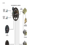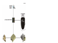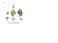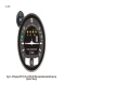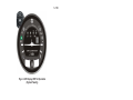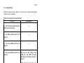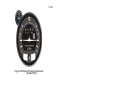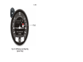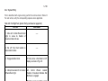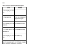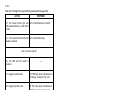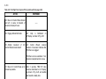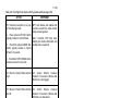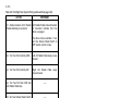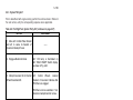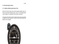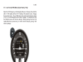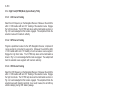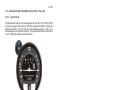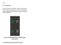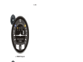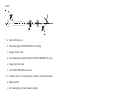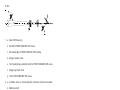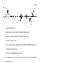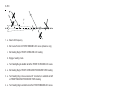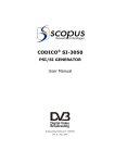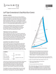
1
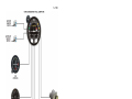
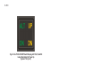
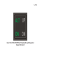
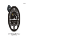
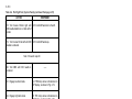
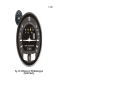
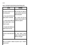
S–TEC
List of Effective Pages
* Asterisk indicates pages changed, added, or deleted by
current revision.
Record of Revisions
Retain this record in front of handbook. Upon receipt of a
revision, insert changes and complete table below.
Revision Number
st
Revision Date
1 Ed.
2nd Ed.
Feb 01, 00
Jun 24, 02
3rd Ed.
Feb 15, 07
3rd Ed. Feb 15, 07
Insertion Date/Initials
i
S–TEC
Page Intentionally Blank
ii
3rd Ed. Feb 15, 07
S–TEC
Table of Contents
Sec.
1
Pg.
Overview...........................................................................................................1–1
1.1
Document Organization....................................................................1–3
1.2
Purpose..............................................................................................1–3
1.3
General Control Theory....................................................................1–3
1.4
Modes of Operation...........................................................................1–4
1.5
2
Roll Axis Control.................................................................1–4
1.4.2
Pitch Axis Control...............................................................1–4
Block Diagrams..................................................................................1–4
Pre-Flight Procedures...................................................................................2–1
2.1
2.2
3
1.4.1
Power-Up Test....................................................................................2–3
2.1.1
System Twenty.....................................................................2–3
2.1.2
System Thirty.......................................................................2–7
2.1.3
System Thirty ALT...............................................................2–13
Pre-Flight Test....................................................................................2–17
2.2.1
System Twenty.....................................................................2–17
2.2.2
System Thirty.......................................................................2–25
2.2.3
System Thirty ALT...............................................................2–35
In-Flight Procedures......................................................................................3–1
3.1
Normal Operating Procedures........................................................3–3
3.1.1
Stabilizer (ST) Mode, System Twenty / Thirty...................3–3
3.1.2
Heading (HD) Mode, System Twenty / Thirty...................3–4
3.1.3
Low Track (LO TRK) Mode, System Twenty / Thirty........3–5
3rd Ed. Feb 15, 07
iii
S–TEC
3.1.4
High Track (HI TRK) Mode, System Twenty / Thirty........3–6
3.1.4.1 LOC Course Tracking........................................3–6
3.1.4.2 GPS Course Tracking........................................3–6
3.1.4.3 VOR Course Tracking........................................3–6
3.1.5
Altitude Hold (ALT HOLD) Mode, System Thirty / Thirty ALT.....3–7
3.1.5.1 System Thirty........................................................3–7
3.1.5.2 System Thirty ALT................................................3–8
3.1.6
Manual Elevator Trim Prompts, System Thirty / Thirty ALT.....3–8
3.1.6.1 System Thirty........................................................3–8
3.1.6.2 System Thirty ALT................................................3–8
3.2
Approach Procedures.......................................................................3–11
3.2.1
Straight-In LOC Approach.................................................3–11
3.2.1.1 Heading System DG..........................................3–11
3.2.1.2 Heading System HSI.........................................3–11
3.2.2
Straight-In VOR Approach.................................................3–11
3.2.2.1 Heading System DG..........................................3–11
3.2.2.2 Heading System HSI.........................................3–11
3.2.3
LOC Approach with Procedure Turn..............................3–16
3.2.3.1 Heading System DG..........................................3–16
3.2.3.2 Heading System HSI.........................................3–16
3.2.4
VOR Approach with Procedure Turn..............................3–19
3.2.4.1 Heading System DG..........................................3–19
3.2.4.2 Heading System HSI.........................................3–19
iv
3rd Ed. Feb 15, 07
S–TEC
3.3
3.4
4
5
Yaw Damper Operation....................................................................3–22
3.3.1
AUTO Mode..........................................................................3–22
3.3.2
ON Mode..............................................................................3–22
3.3.3
Yaw Damper Trim..............................................................3–22
Autopilot Disconnect ........................................................................3–23
3.4.1
System Twenty / Thirty.......................................................3–23
3.4.2
System Thirty ALT...............................................................3–23
Operating Parameters..................................................................................4–1
4.1
Roll Axis Limits..................................................................................4–3
4.2
Pitch Axis Limits.................................................................................4–3
Glossary...........................................................................................................5–1
3rd Ed. Feb 15, 07
v
S–TEC
List of Figures
Fig.
Pg.
1–1
System Twenty Block Diagram....................................................................1–5
1–2
System Thirty Block Diagram......................................................................1–6
1–3
System Thirty ALT Block Diagram...............................................................1–7
1–4
Yaw Damper Block Diagram.......................................................................1–8
2–1
AP Display, Lamps Illuminated at Power-Up (System Twenty)...............2–4
2–2
AP Display, All Lamps Extinguished (System Twenty).............................2–4
2–3
AP Display, RDY for Operation....................................................................2–5
2–4
AP Display, Turn Coordinator Failure (System Twenty)...........................2–5
2–5
AP Display, Low Voltage Flag (System Twenty).........................................2–6
2–6
AP Display, Lamps Illuminated at Power-Up (System Thirty).................2–8
2–7
AP Display, TRIM UP Lamp Extinguished (System Thirty).......................2–8
2–8
AP Display, ALT Lamp Only Illuminated (System Thirty)...........................2–9
2–9
AP Display, All Lamps Extinguished (System Thirty)................................2–9
2–10 AP Display, RDY for Operation (System Thirty).......................................2–10
2–11 AP Display, Turn Coordinator Failure (System Thirty)............................2–10
2–12 AP Display, Low Voltage Flag (System Thirty).........................................2–11
2–13
ALT HOLD ON/OFF Switch Display, Lamps Illuminated at Power-Up (System Thirty ALT)....2–14
2–14
ALT HOLD ON/OFF Switch Display, UP Lamp Extinguished (System Thirty ALT)...............2–14
2–15
ALT HOLD ON/OFF Switch Display, DN Lamp Extinguished (System Thirty ALT)..............2–15
2–16
ALT HOLD ON/OFF Switch Display, ALT ON Lamp Extinguished (System Thirty ALT).........2–15
2–17 AP Display, ST Mode Engaged (System Twenty)....................................2–19
2–18 AP Display, HD Mode Engaged (System Twenty)...................................2–19
2–19 AP Display, LO TRK Mode Engaged (System Twenty)...........................2–21
vi
3rd Ed. Feb 15, 07
S–TEC
2–20 AP Display, HI TRK Mode Engaged (System Twenty)...........................2–21
2–21 AP Display, ST Mode Engaged (System Thirty).......................................2–27
2–22 AP Display, HD Mode Engaged (System Thirty)......................................2–27
2–23 AP Display, LO TRK Mode Engaged (System Thirty)..............................2–29
2–24 AP Display, LO TRK Mode Engaged (System Thirty)..............................2–29
2–25 AP Display, HI TRK and ALT HOLD Modes Engaged (System Thirty)........2–31
2–26
AP Display, HI TRK and ALT HOLD ModeS Engaged, TRIM UP Required (System Thirty).....2–32
2–27
AP Display, HI TRK and ALT HOLD ModeS Engaged, TRIM DN Required (System Thirty).....2–32
2–28
ALT HOLD ON/OFF Switch Display, ALT HOLD Mode Engaged (System Thirty ALT).......2–36
2–29
ALT HOLD ON/OFF Switch Display, ALT HOLD Mode Engaged, TRIM UP Required (System Thirty ALT).....2–36
2–30
ALT HOLD ON/OFF Switch Display, ALT HOLD Mode Engaged, TRIM DN Required (System Thirty ALT).....2–36
3–1
AP Display, ST Mode Engaged....................................................................3–3
3–2
AP Display, HD Mode Engaged...................................................................3–4
3–3
AP Display, LO TRK Mode Engaged...........................................................3–5
3–4
AP Display, HI TRK Mode Engaged............................................................3–6
3–5
AP Display, ST and ALT HOLD Modes Engaged (System Thirty)............3–7
3–6
ALT HOLD ON/OFF Switch Display, ALT HOLD Mode Engaged (System Thirty ALT)............3–8
3–7
AP Display, Manual Trim Prompts (System Thirty)...................................3–9
3–8
AP Display, Manual Trim Prompts (System Thirty ALT)..........................3–10
3–9
Straight-In LOC Approach (DG)..................................................................3–12
3–10 Straight-In LOC Approach (HSI)..................................................................3–13
3–11 Straight-In VOR Approach (DG)..................................................................3–14
3–12 Straight-In VOR Approach (HSI)..................................................................3–15
3–13 LOC Approach with Procedure Turn (DG)................................................3–17
3rd Ed. Feb 15, 07
vii
S–TEC
3–14 LOC Approach with Procedure Turn (HSI)...............................................3–18
3–15 VOR Approach with Procedure Turn (DG)................................................3–20
3–16 VOR Approach with Procedure Turn (HSI)...............................................3–21
3–17 Yaw Damper Master Switch........................................................................3–22
3–18 Yaw Damper Trim Knob..............................................................................3–22
List of Tables
Table
Pg.
2–1
Power-Up Test, System Twenty...................................................................2–3
2–2
Power-Up Test, System Thirty.....................................................................2–7
2–3
Power-Up Test, System Thirty ALT.............................................................2–13
2–4
Pre-Flight Test, System Twenty...................................................................2–17
2–5
Pre-Flight Test, System Thirty.....................................................................2–25
2–6
Pre-Flight Test, System Thirty ALT.............................................................2–35
viii
3rd Ed. Feb 15, 07
S–TEC
SECTION 1
OVERVIEW
3rd Ed. Feb 15, 07
1-1
S–TEC
Page Intentionally Blank
1-2
3rd Ed. Feb 15, 07
S–TEC
1.1 Document Organization
Section 1 Overview
Section 2 Pre-Flight Procedures
Section 3 In-Flight Procedures
Section 4 Operating Parameters
Section 5 Glossary
1.2 Purpose
This Pilot's Operating Handbook (POH) provides Pre-Flight and In-Flight
operating procedures for the S-TEC System Twenty / Thirty / Thirty ALT Autopilot
(AP).
Note:
This POH must be carried in the aircraft and made available to the pilot at all
times. It can only be used in conjunction with the Federal Aviation
Administration (FAA) approved Aircraft Flight Manual (AFM) or Aircraft Flight
Manual Supplement (AFMS). Refer to the applicable AFM or AFMS for
aircraft specific information, such as unique ground tests, limitations, and
emergency procedures.
Note:
The System Twenty / Thirty / Thirty ALT autopilot is a tool provided to aircraft
owners, that serves to assist them with cockpit workload management. The
ability of the autopilot to provide optimum assistance and performance is
directly proportional to the pilot's knowledge of its operating procedures.
Therefore, it is highly recommended that the pilot develop a thorough
understanding of the autopilot, its modes, and operating procedures in
Visual Meteorological Conditions (VMC), prior to using it under Instrument
Flight Rules (IFR).
1.3 General Control Theory
The System Twenty / Thirty / Thirty ALT is a rate based autopilot. When in control
of the roll axis, the autopilot senses turn rate, along with the non-rate quantities
of heading error and course deviation indication. When in control of the pitch
axis, the autopilot senses acceleration, along with the non-rate quantity of
altitude. These sensed data provide feedback to the autopilot, which processes
them in order to control the aircraft through the use of mechanisms coupled
to the control system. The roll servo is typically coupled to the ailerons, and
the pitch servo is coupled to the elevator.
The System Twenty controls only the roll axis.
The System Thirty controls both the roll axis and pitch axis. Activation of roll axis
control must always precede activation of pitch axis control.
The System Thirty ALT controls only the pitch axis.
3rd Ed. Feb 15, 07
1-3
S–TEC
The optional Yaw Damper senses excessive adverse yaw about the yaw axis,
and responds by driving the yaw servo in the proper direction to provide
damping. The yaw servo is coupled to the rudder.
1.4 Modes of Operation
1.4.1 Roll Axis Control
Each press/release of the optional MODE SEL Switch typically located on the
Control Wheel, or PUSH MODE Switch located on the bezel, successively
engages the roll modes below.
Stabilizer (ST) Mode
Used to Hold Wings Level
Heading (HD) Mode
Used to Turn onto a Selected Heading and Hold it
Low Track (LO TRK) Mode
Used to Track a VOR Course
High Track (HI TRK) Mode
Used to Track a LOC Course
Note:
A heading system (HSI or DG) is optional. If the aircraft is equipped with a
heading system, then the heading mode can be engaged. Otherwise, the
heading mode cannot be engaged (i.e., it will be skipped over).
1.4.2 Pitch Axis Control
Each press of the ALT ENG/DSNG Switch typically located on the Control
Wheel (optional for System Thirty ALT only), or ALT HOLD ON/OFF Switch
located on the instrument panel (System Thirty ALT only), successively engages
and disengages the single pitch mode below.
Altitude Hold (ALT HOLD) Mode
Used to Hold Altitude
1.5 Block Diagrams
The System Twenty Block Diagram is shown in Fig. 1-1.
The System Thirty Block Diagram is shown in Fig. 1-2.
The System Thirty ALT Block Diagram is shown in Fig. 1-3.
The Yaw Damper Block Diagram is shown in Fig. 1-4.
1-4
3rd Ed. Feb 15, 07
S–TEC
Fig. 1-1. System Twenty Block Diagram
3rd Ed. Feb 15, 07
1-5
S–TEC
Fig. 1-2. System Thirty Block Diagram
1-6
3rd Ed. Feb 15, 07
S–TEC
Fig. 1-3. System Thirty ALT Block Diagram
3rd Ed. Feb 15, 07
1-7
S–TEC
Fig. 1-4. Yaw Damper Block Diagram
1-8
3rd Ed. Feb 15, 07
S–TEC
SECTION 2
PRE-FLIGHT PROCEDURES
3rd Ed. Feb 15, 07
2-1
S–TEC
Page Intentionally Blank
2-2
3rd Ed. Feb 15, 07
S–TEC
2.1 Power-Up Test
2.1.1 System Twenty
Perform the actions shown in Table 2-1. For each action, verify the corresponding
response where applicable.
Table 2-1. Power-Up Test, System Twenty
ACTION
RESPONSE
1. Set Yaw Damper Master Switch to
OFF position (if installed).
------
2. Set Battery Master Switch to ON
position.
------
3. Set Avionics Master Switch to ON
position.
------
4. Set Autopilot Master Switch to ON
position.
RDY, ST, HD, LO TRK, and HI TRK
lamps illuminate on AP display as
shown in Fig. 2-1 for 7 seconds, and
then extinguish as shown in Fig. 2-2.
RDY lamp alone re-illuminates on AP
display within 3 minutes, as shown in
Fig. 2-3 (Note 1).
Notes:
1. Should a Turn Coordinator failure be detected, the RDY lamp on the AP
display will not re-illuminate as shown in Fig. 2-4, and the autopilot will not
operate.
2. Should T&B A+ be 30% below its rated value, the Low Voltage Flag will be in
view on the AP display as shown in Fig. 2-5.
3rd Ed. Feb 15, 07
2-3
S–TEC
Fig. 2-1. AP Display, RDY, ST, HD, LO TRK, HI TRK Lamps Illuminated at Power-Up
(System Twenty)
Fig. 2-2. AP Display, All Lamps Extinguished
(System Twenty)
2-4
3rd Ed. Feb 15, 07
S–TEC
Fig. 2-3. AP Display, RDY for Operation
(System Twenty)
Fig. 2-4. AP Display, Turn Coordinator Failure
(System Twenty)
3rd Ed. Feb 15, 07
2-5
S–TEC
Fig. 2-5. AP Display, Low Voltage Flag
(System Twenty)
2-6
3rd Ed. Feb 15, 07
S–TEC
2.1.2 System Thirty
Perform the actions shown in Table 2-2. For each action, verify the corresponding
response where applicable.
Table 2-2. Power-Up Test, System Thirty
ACTION
RESPONSE
1. Set Yaw Damper Master Switch to
OFF position (if installed).
------
2. Set Battery Master Switch to ON
position.
------
3. Set Avionics Master Switch to ON
position.
------
4. Set Autopilot Master Switch to ON
position.
RDY, ALT, ST, HD, LO TRK, HI TRK,
TRIM UP, and TRIM DN lamps
illuminate on AP display as shown in
Fig. 2-6.
TRIM UP lamp extinguishes after
2 seconds, as shown in Fig. 2-7.
RDY, ST, HD, LO TRK, HI TRK, and
TRIM DN lamps extinguish after
7 seconds, as shown in Fig. 2-8.
ALT
lamp
extinguishes
after
10 seconds, as shown in Fig. 2-9.
RDY lamp alone re-illuminates on AP
display within 3 minutes, as shown in
Fig. 2-10 (Note 1).
Notes:
1. Should a Turn Coordinator failure be detected, the RDY lamp on the AP
display will not re-illuminate as shown in Fig. 2-11, and the autopilot will not
operate.
2. Should T&B A+ be 30% below its rated value, the Low Voltage Flag will be in
view on the AP display as shown in Fig. 2-12.
3rd Ed. Feb 15, 07
2-7
S–TEC
Fig. 2-6. AP Display, RDY, ALT, ST, HD, LO TRK, HI TRK, TRIM UP, TRIM DN
Lamps Illuminated at Power-Up
(System Thirty)
Fig. 2-7. AP Display, TRIM UP Lamp Extinguished
(System Thirty)
2-8
3rd Ed. Feb 15, 07
S–TEC
Fig. 2-8. AP Display, ALT Lamp Only Illuminated
(System Thirty)
Fig. 2-9. AP Display, All Lamps Extinguished
(System Thirty)
3rd Ed. Feb 15, 07
2-9
S–TEC
Fig. 2-10. AP Display, RDY for Operation
(System Thirty)
Fig. 2-11. AP Display, Turn Coordinator Failure
(System Thirty)
2-10
3rd Ed. Feb 15, 07
S–TEC
Fig. 2-12. AP Display, Low Voltage Flag
(System Thirty)
3rd Ed. Feb 15, 07
2-11
S–TEC
Page Intentionally Blank
2-12
3rd Ed. Feb 15, 07
S–TEC
2.1.3 System Thirty ALT
Perform the actions shown in Table 2-3. For each action, verify the corresponding
response where applicable.
Table 2-3. Power-Up Test, System Thirty ALT
ACTION
RESPONSE
1. Set Yaw Damper Master Switch to
OFF position (if installed).
------
2. Set Battery Master Switch to ON
position.
------
3. Set Avionics Master Switch to ON
position.
------
4. Set ALT HOLD Master Switch to
ON position.
ALT ON, UP, and DN lamps
illuminate on ALT HOLD ON/OFF
Switch display, as shown in Fig. 2-13.
UP
lamp
extinguishes
after
2 seconds, as shown in Fig. 2-14.
DN
lamp
extinguishes
after
7 seconds, as shown in Fig. 2-15.
ALT ON lamp extinguishes after
10 seconds, as shown in Fig. 2-16.
3rd Ed. Feb 15, 07
2-13
S–TEC
Fig. 2-13. ALT HOLD ON/OFF Switch Display, ALT ON, UP, and DN
Lamps Illuminated at Power-Up
(System Thirty ALT)
Fig. 2-14. ALT HOLD ON/OFF Switch Display, UP Lamp Extinguished
(System Thirty ALT)
2-14
3rd Ed. Feb 15, 07
S–TEC
Fig. 2-15. ALT HOLD ON/OFF Switch Display, DN Lamp Extinguished
(System Thirty ALT)
Fig. 2-16. ALT HOLD ON/OFF Switch Display, ALT ON Lamp Extinguished
(System Thirty ALT)
3rd Ed. Feb 15, 07
2-15
S–TEC
Page Intentionally Blank
2-16
3rd Ed. Feb 15, 07
S–TEC
2.2 Pre-Flight Test
2.2.1 System Twenty
Prior to takeoff and with engine running, perform the actions shown in Table 2-4.
For each action, verify the corresponding response where applicable.
Table 2-4. Pre-Flight Test, System Twenty (continued on page 2-18)
ACTION
RESPONSE
1. Move A/C Control Wheel left and
right, to sense its freedom of
movement about roll axis.
------
2. Set L/R Turn Knob located on
bezel under its index.
------
3. Engage stabilizer mode.
ST lamp alone is illuminated on AP
display, as shown in Fig. 2-17.
4. Attempt movement of A/C Control
Wheel left and right.
A/C
Control
Wheel’s
reduced
freedom of movement indicates that
Roll Servo is engaged.
Roll Servo can be overridden. If not,
disconnect autopilot and do not use.
5. Turn L/R Turn Knob to the left
side of its index.
A/C Control Wheel turns to the left.
6. Turn L/R Turn Knob to the right
side of its index.
A/C Control Wheel turns to the right.
7. Set L/R Turn Knob under its
index.
A/C Control Wheel stops.
Note:
If A/C is equipped with a heading system (HSI or DG), then proceed to step 8.
If A/C is not equipped with a heading system, then proceed to step 13 only if a
VOR frequency can be selected. Otherwise, proceed to step 26.
3rd Ed. Feb 15, 07
2-17
S–TEC
Table 2-4. Pre-Flight Test, System Twenty (continued from page 2-17)
ACTION
RESPONSE
8. Set Heading Bug under Lubber
Line.
------
9.
Engage heading mode.
HD lamp alone is illuminated on AP
display, as shown in Fig. 2-18.
10. Turn Heading Bug to the left side
of Lubber Line.
A/C Control Wheel turns to the left.
11. Turn Heading Bug to the right
side of Lubber Line.
A/C Control Wheel turns to the right.
12. Set Heading Bug under Lubber
Line.
A/C Control Wheel stops.
Note: If it is not possible to select a local VOR frequency on Navigation
Receiver, then proceed to step 26. Otherwise, proceed to step 13.
13. Select local VOR frequency on
Navigation Receiver.
------
Note: Proceed to either step 14 (HSI) or step 20 (DG).
14. Turn Course Pointer until CDI
needle is centered.
------
15. Engage low track mode.
LO TRK lamp alone is illuminated on
AP display, as shown in Fig. 2-19.
16. Engage high track mode.
HI TRK lamp alone is illuminated on
AP display, as shown in Fig. 2-20.
17. Turn Course Pointer left until CDI
needle deflection is 2 dots right of
center.
A/C Control Wheel turns to the right.
2-18
3rd Ed. Feb 15, 07
S–TEC
Fig. 2-17. AP Display, ST Mode Engaged
(System Twenty)
Fig. 2-18. AP Display, HD Mode Engaged
(System Twenty)
3rd Ed. Feb 15, 07
2-19
S–TEC
Table 2-4. Pre-Flight Test, System Twenty (continued from page 2-18)
ACTION
RESPONSE
18. Turn Course Pointer right until
CDI needle deflection is 2 dots left of
center.
A/C Control Wheel turns to the left.
19. Turn Course Pointer left until CDI
needle is centered.
A/C Control Wheel stops.
Note: Proceed to step 28.
20. Turn OBS until CDI needle is
centered.
------
21. Engage low track mode.
LO TRK lamp alone is illuminated on
AP display, as shown in Fig. 2-19.
22. Engage high track mode.
HI TRK lamp alone is illuminated on
AP display, as shown in Fig. 2-20.
23. Turn OBS until CDI needle
deflection is 2 dots right of center.
A/C Control Wheel turns to the right.
24. Turn OBS until CDI needle
deflection is 2 dots left of center.
A/C Control Wheel turns to the left.
25. Turn OBS until CDI needle is
centered.
A/C Control Wheel stops.
Note: Proceed to step 28.
26. Engage low track mode.
LO TRK lamp alone is illuminated on
AP display, as shown in Fig. 2-19.
27. Engage high track mode.
HI TRK lamp alone is illuminated on
AP display, as shown in Fig. 2-20.
2-20
3rd Ed. Feb 15, 07
S–TEC
Fig. 2-19. AP Display, LO TRK Mode Engaged
(System Twenty)
Fig. 2-20. AP Display, HI TRK Mode Engaged
(System Twenty)
3rd Ed. Feb 15, 07
2-21
S–TEC
Table 2-4. Pre-Flight Test, System Twenty (continued from page 2-20)
ACTION
RESPONSE
28. Disconnect autopilot by any one
of the following means:
RDY lamp flashes and audible alert
sounds a periodic tone, while all other
lamps are extinguished.
a. Press optional AP DISC Switch
typically located on Control Wheel.
b. Press/Hold optional MODE SEL
Switch typically located on Control
Wheel for 3 seconds.
After 5 seconds, RDY lamp stops
flashing but remains illuminated, and
audible alert is squelched.
c. Press/Hold PUSH MODE Switch
located on bezel for 3 seconds.
29. Move A/C Control Wheel left and
right.
A/C Control Wheel’s increased
freedom of movement indicates that
Roll Servo is disengaged.
Note: If a Yaw Damper is installed, then proceed to step 30.
proceed to step 39.
Otherwise,
30. Actuate A/C Rudder Pedals
alternately in succession, to sense
their freedom of movement about yaw
axis.
------
31. Set Yaw Damper Master Switch
to ON position.
------
32. Turn Yaw Trim Knob until A/C
Rudder Pedals stop.
------
33. Attempt actuation of A/C Rudder
Pedals alternately in succession.
A/C Rudder Pedals’ reduced freedom
of movement indicates that Yaw
Servo is engaged.
Yaw Servo can be overridden. If not,
set Yaw Damper Master Switch to
OFF position, and do not use.
2-22
3rd Ed. Feb 15, 07
S–TEC
Table 2-4. Pre-Flight Test, System Twenty (continued from page 2-22)
ACTION
RESPONSE
34. Turn Yaw Trim Knob fully CCW.
Left A/C Rudder Pedal slowly moves
forward.
35. Turn Yaw Trim Knob fully CW.
Right A/C Rudder
moves forward.
36. Turn Yaw Trim Knob CCW until
A/C Rudder Pedals stop.
------
37. Set Yaw Damper Master Switch
to OFF position.
------
38. Actuate A/C Rudder
alternately in succession.
39. Trim A/C for takeoff.
3rd Ed. Feb 15, 07
Pedals
Pedal
slowly
A/C Rudder Pedals’ increased
freedom of movement indicates that
Yaw Servo is disengaged.
------
2-23
S–TEC
Page Intentionally Blank
2-24
3rd Ed. Feb 15, 07
S–TEC
2.2.2 System Thirty
Prior to takeoff and with engine running, perform the actions shown in Table 2-5.
For each action, verify the corresponding response where applicable.
Table 2-5. Pre-Flight Test, System Thirty (continued on page 2-26)
ACTION
RESPONSE
1. Move A/C Control Wheel left and
right, to sense its freedom of
movement about roll axis.
------
2. Set L/R Turn Knob located on
bezel under its index.
------
3. Engage stabilizer mode.
ST lamp alone is illuminated on AP
display, as shown in Fig. 2-21.
4. Attempt movement of A/C Control
Wheel left and right.
A/C
Control
Wheel’s
reduced
freedom of movement indicates that
Roll Servo is engaged.
Roll Servo can be overridden. If not,
disconnect autopilot and do not use.
5. Turn L/R Turn Knob to the left
side of its index.
A/C Control Wheel turns to the left.
6. Turn L/R Turn Knob to the right
side of its index.
A/C Control Wheel turns to the right.
7. Set L/R Turn Knob under its
index.
A/C Control Wheel stops.
Note:
If A/C is equipped with a heading system (HSI or DG), then proceed to step 8.
If A/C is not equipped with a heading system, then proceed to step 13 only if a
VOR frequency can be selected. Otherwise, proceed to step 26.
3rd Ed. Feb 15, 07
2-25
S–TEC
Table 2-5. Pre-Flight Test, System Thirty (continued from page 2-25)
ACTION
RESPONSE
8. Set Heading Bug under Lubber
Line.
------
9.
Engage heading mode.
HD lamp alone is illuminated on AP
display, as shown in Fig. 2-22.
10. Turn Heading Bug to the left side
of Lubber Line.
A/C Control Wheel turns to the left.
11. Turn Heading Bug to the right
side of Lubber Line.
A/C Control Wheel turns to the right.
12. Set Heading Bug under Lubber
Line.
A/C Control Wheel stops.
Note: If it is not possible to select a local VOR frequency on Navigation
Receiver, then proceed to step 26. Otherwise, proceed to step 13.
13. Select local VOR frequency on
Navigation Receiver.
------
Note: Proceed to either step 14 (HSI) or step 20 (DG).
14. Turn Course Pointer until CDI
needle is centered.
------
15. Engage low track mode.
LO TRK lamp alone is illuminated on
AP display, as shown in Fig. 2-23.
16. Engage high track mode.
HI TRK lamp alone is illuminated on
AP display, as shown in Fig. 2-24.
17. Turn Course Pointer left until CDI
needle deflection is 2 dots right of
center.
A/C Control Wheel turns to the right.
2-26
3rd Ed. Feb 15, 07
S–TEC
Fig. 2-21. AP Display, ST Mode Engaged
(System Thirty)
Fig. 2-22. AP Display, HD Mode Engaged
(System Thirty)
3rd Ed. Feb 15, 07
2-27
S–TEC
Table 2-5. Pre-Flight Test, System Thirty (continued from page 2-26)
ACTION
RESPONSE
18. Turn Course Pointer right until
CDI needle deflection is 2 dots left of
center.
A/C Control Wheel turns to the left.
19. Turn Course Pointer left until CDI
needle is centered.
A/C Control Wheel stops.
Note: Proceed to step 28.
20. Turn OBS until CDI needle is
centered.
------
21. Engage low track mode.
LO TRK lamp alone is illuminated on
AP display, as shown in Fig. 2-23.
22. Engage high track mode.
HI TRK lamp alone is illuminated on
AP display, as shown in Fig. 2-24.
23. Turn OBS until CDI needle
deflection is 2 dots right of center.
A/C Control Wheel turns to the right.
24. Turn OBS until CDI needle
deflection is 2 dots left of center.
A/C Control Wheel turns to the left.
25. Turn OBS until CDI needle is
centered.
A/C Control Wheel stops.
Note: Proceed to step 28.
26. Engage low track mode.
LO TRK lamp alone is illuminated on
AP display, as shown in Fig. 2-23.
27. Engage high track mode.
HI TRK lamp alone is illuminated on
AP display, as shown in Fig. 2-24.
2-28
3rd Ed. Feb 15, 07
S–TEC
Fig. 2-23. AP Display, LO TRK Mode Engaged
(System Thirty)
Fig. 2-24. AP Display, HI TRK Mode Engaged
(System Thirty)
3rd Ed. Feb 15, 07
2-29
S–TEC
Table 2-5. Pre-Flight Test, System Thirty (continued from page 2-28)
ACTION
RESPONSE
28. Move A/C Control Wheel forward
and aft, to sense its freedom of
movement about pitch axis.
------
29. Engage altitude hold mode.
30. Attempt movement of
Control Wheel forward and aft.
ALT
lamp is
illuminated
on
AP display, as shown in Fig. 2-25.
A/C
A/C
Control
Wheel’s
reduced
freedom of movement indicates that
Pitch Servo is engaged.
Pitch Servo can be overridden. If not,
disconnect autopilot and do not use.
31. Move A/C Control Wheel as far
forward as possible.
After 3 seconds, TRIM UP lamp
becomes illuminated on AP display
as shown in Fig. 2-26, and audible
alert sounds a steady tone.
After 7 seconds, TRIM UP lamp
flashes and audible alert becomes
periodic.
32. Move A/C Control Wheel aft until
TRIM UP lamp is extinguished.
Audible alert is squelched.
33. Move A/C Control Wheel as far
aft as possible.
After 3 seconds, TRIM DN lamp
becomes illuminated on AP display
as shown in Fig. 2-27, and audible
alert sounds a steady tone.
After 7 seconds, TRIM DN lamp
flashes and audible alert becomes
periodic.
34. Move A/C Control Wheel forward
until TRIM DN lamp is extinguished.
2-30
Audible alert is squelched.
3rd Ed. Feb 15, 07
S–TEC
Fig. 2-25. AP Display, HI TRK and ALT HOLD Modes Engaged
(System Thirty)
3rd Ed. Feb 15, 07
2-31
S–TEC
Fig. 2-26. AP Display, HI TRK and ALT HOLD Modes Engaged, TRIM UP Required
(System Thirty)
Fig. 2-27. AP Display, HI TRK and ALT HOLD Modes Engaged, TRIM DN Required
(System Thirty)
2-32
3rd Ed. Feb 15, 07
S–TEC
Table 2-5. Pre-Flight Test, System Thirty (continued from page 2-30)
ACTION
RESPONSE
35. Disconnect autopilot by any one
of the following means:
RDY lamp flashes and audible alert
sounds a periodic tone, while all other
lamps are extinguished.
a. Press optional AP DISC Switch
typically located on Control Wheel.
b. Press/Hold optional MODE SEL
Switch typically located on Control
Wheel for 3 seconds.
After 5 seconds, RDY lamp stops
flashing but remains illuminated, and
audible alert is squelched.
c. Press/Hold PUSH MODE Switch
located on bezel for 3 seconds.
36. Move A/C Control Wheel left and
right.
A/C Control Wheel’s increased
freedom of movement indicates that
Roll Servo is disengaged.
37. Move A/C Control Wheel forward
and aft.
A/C Control Wheel’s increased
freedom of movement indicates that
Pitch Servo is disengaged.
Note: If a Yaw Damper is installed, then proceed to step 38.
proceed to step 47.
38. Actuate A/C Rudder Pedals
alternately in succession, to sense
their freedom of movement about yaw
axis.
------
39. Set Yaw Damper Master Switch
to ON position.
------
40. Turn Yaw Trim Knob until A/C
Rudder Pedals stop.
------
3rd Ed. Feb 15, 07
Otherwise,
2-33
S–TEC
Table 2-5. Pre-Flight Test, System Thirty (continued from page 2-33)
ACTION
RESPONSE
41. Attempt actuation of A/C Rudder
Pedals alternately in succession.
A/C Rudder Pedals’ reduced freedom
of movement indicates that Yaw
Servo is engaged.
Yaw Servo can be overridden. If not,
set Yaw Damper Master Switch to
OFF position, and do not use.
42. Turn Yaw Trim Knob fully CCW.
Left A/C Rudder Pedal slowly moves
forward.
43. Turn Yaw Trim Knob fully CW.
Right A/C Rudder
moves forward.
44. Turn Yaw Trim Knob CCW until
A/C Rudder Pedals stop.
------
45. Set Yaw Damper Master Switch
to OFF position.
------
46. Actuate A/C Rudder
alternately in succession.
47. Trim A/C for takeoff.
2-34
Pedals
Pedal
slowly
A/C Rudder Pedals’ increased
freedom of movement indicates that
Yaw Servo is disengaged.
------
3rd Ed. Feb 15, 07
S–TEC
2.2.3 System Thirty ALT
Prior to takeoff and with engine running, perform the actions shown in Table 2-6.
For each action, verify the corresponding response where applicable.
Table 2-6. Pre-Flight Test, System Thirty ALT (continued on page 2-37)
ACTION
RESPONSE
1. Move A/C Control Wheel forward
and aft, to sense its freedom of
movement about pitch axis.
------
2. Engage altitude hold mode.
ALT ON lamp is illuminated on
ALT HOLD ON/OFF Switch display,
as shown in Fig. 2-28.
3. Attempt movement of A/C Control
Wheel forward and aft.
A/C
Control
Wheel’s
reduced
freedom of movement indicates that
Pitch Servo is engaged.
Pitch Servo can be overridden. If not,
disconnect autopilot and do not use.
4. Move A/C Control Wheel as far
forward as possible.
After 3 seconds, UP lamp becomes
illuminated on ALT HOLD ON/OFF
Switch display as shown in Fig. 2-29,
and audible alert sounds a steady
tone.
After 7 seconds, UP lamp flashes and
audible alert becomes periodic.
5. Move A/C Control Wheel aft until
UP lamp is extinguished.
Audible alert is squelched.
6. Move A/C Control Wheel as far aft
as possible.
After 3 seconds, DN lamp becomes
illuminated on ALT HOLD ON/OFF
Switch display as shown in Fig. 2-30,
and audible alert sounds a steady
tone.
After 7 seconds, DN lamp flashes and
audible alert becomes periodic.
3rd Ed. Feb 15, 07
2-35
S–TEC
Fig. 2-28. ALT HOLD ON/OFF Switch Display, ALT HOLD Mode Engaged
(System Thirty ALT)
Fig. 2-29. ALT HOLD ON/OFF Switch Display, ALT HOLD Mode Engaged,
TRIM UP Required
(System Thirty ALT)
Fig. 2-30. ALT HOLD ON/OFF Switch Display, ALT HOLD Mode Engaged,
TRIM DN Required
(System Thirty ALT)
2-36
3rd Ed. Feb 15, 07
S–TEC
Table 2-6. Pre-Flight Test, System Thirty ALT (continued from page 2-35)
ACTION
RESPONSE
7. Move A/C Control Wheel forward
until DN lamp is extinguished.
Audible alert is squelched.
8. Disengage altitude hold mode.
ALT ON lamp is extinguished on
ALT HOLD ON/OFF Switch display.
9. Move A/C Control Wheel forward
and aft.
A/C Control Wheel’s increased
freedom of movement indicates that
Pitch Servo is disengaged.
Note: If a Yaw Damper is installed, then proceed to step 10.
proceed to step 19.
Otherwise,
10. Actuate A/C Rudder Pedals
alternately in succession, to sense
their freedom of movement about yaw
axis.
------
11. Set Yaw Damper Master Switch
to ON position.
------
12. Turn Yaw Trim Knob until A/C
Rudder Pedals stop.
------
13. Attempt actuation of A/C Rudder
Pedals alternately in succession.
A/C Rudder Pedals’ reduced freedom
of movement indicates that Yaw
Servo is engaged.
Yaw Servo can be overridden. If not,
set Yaw Damper Master Switch to
OFF position, and do not use.
14. Turn Yaw Trim Knob fully CCW.
Left A/C Rudder Pedal slowly moves
forward.
15. Turn Yaw Trim Knob fully CW.
Right A/C Rudder
moves forward.
3rd Ed. Feb 15, 07
Pedal
slowly
2-37
S–TEC
Table 2-5. Pre-Flight Test, System Thirty ALT (continued from page 2-37)
ACTION
RESPONSE
16. Turn Yaw Trim Knob CCW until
A/C Rudder Pedals stop.
------
17. Set Yaw Damper Master Switch
to OFF position.
------
18. Actuate A/C Rudder
alternately in succession.
19. Trim A/C for takeoff.
2-38
Pedals
A/C Rudder Pedals’ increased
freedom of movement indicates that
Yaw Servo is disengaged.
------
3rd Ed. Feb 15, 07
S–TEC
SECTION 3
IN-FLIGHT PROCEDURES
3rd Ed. Feb 15, 07
3-1
S–TEC
Page Intentionally Blank
3-2
3rd Ed. Feb 15, 07
S–TEC
3.1 Normal Operating Procedures
3.1.1 Stabilizer (ST) Mode, System Twenty / Thirty
Set the L/R Turn Knob under its index, and then engage the stabilizer mode. The
ST lamp alone will be illuminated as shown in Fig. 3-1, to acknowledge that this
mode is engaged. The autopilot will hold the aircraft at wings level.
Turning the L/R Turn Knob to the left or right of its index will cause the aircraft to
turn either left or right, respectively. The L/R Turn Knob is active only when the
stabilizer mode is engaged.
Fig. 3-1. AP Display, ST Mode Engaged
3rd Ed. Feb 15, 07
3-3
S–TEC
3.1.2 Heading (HD) Mode, System Twenty / Thirty
Set the Heading Bug to the desired heading on the compass card (HSI or DG),
and then engage the heading mode. The HD lamp alone will be illuminated as
shown in Fig. 3-2, to acknowledge that this mode is engaged. The autopilot will
turn the aircraft onto the selected heading and hold it. A new heading can be
subsequently selected by setting the Heading Bug to it.
Fig. 3-2. AP Display, HD Mode Engaged
3-4
3rd Ed. Feb 15, 07
S–TEC
3.1.3 Low Track (LO TRK) Mode, System Twenty / Thirty
Select the VOR frequency on the Navigation Receiver. Maneuver the aircraft to
within ±1 CDI needle width and ±10° heading of the selected course. Engage
the low track mode. The LO TRK lamp alone will be illuminated as shown
in Fig. 3-3, to acknowledge that this mode is engaged. The autopilot will track
the selected course with minimum authority, thereby ignoring short term CDI
needle deflections (excursions) to inhibit aircraft scalloping during VOR
station passage.
Fig. 3-3. AP Display, LO TRK Mode Engaged
3rd Ed. Feb 15, 07
3-5
S–TEC
3.1.4 High Track (HI TRK) Mode, System Twenty / Thirty
3.1.4.1 LOC Course Tracking
Select the LOC frequency on the Navigation Receiver. Maneuver the aircraft to
within ±1 CDI needle width and ±10° heading of the selected course. Engage
the high track mode. The HI TRK lamp alone will be illuminated as shown in
Fig. 3-4, to acknowledge that this mode is engaged. The autopilot will track the
selected course with maximum authority.
3.1.4.2 GPS Course Tracking
Program a predefined course into the GPS Navigation Receiver, comprised of
course segments connected by waypoints. Maneuver the aircraft to within
±1 CDI needle width and ±10° heading of each successive course segment.
Engage the high track mode. The HI TRK lamp alone will be illuminated as
shown in Fig. 3-4, to acknowledge that this mode is engaged. The autopilot will
track the selected course segment with maximum authority.
3.1.4.3 VOR Course Tracking
Select the VOR frequency on the Navigation Receiver. Maneuver the aircraft to
within ±1 CDI needle width and ±10° heading of the selected course. Engage
the high track mode. The HI TRK lamp alone will be illuminated as shown in
Fig. 3-4, to acknowledge that this mode is engaged. The autopilot will track the
selected course with maximum authority. As a result, however, the aircraft may
exhibit scalloping during VOR station passage.
Fig. 3-4. AP Display, HI TRK Mode Engaged
3-6
3rd Ed. Feb 15, 07
S–TEC
3.1.5 Altitude Hold (ALT HOLD) Mode, System Thirty / Thirty ALT
3.1.5.1 System Thirty
The altitude hold mode can only be engaged if a roll mode (ST, HD, LO TRK, HI TRK)
is already engaged. Maneuver the aircraft to the desired altitude. Engage the
altitude hold mode. The ALT lamp will be illuminated as shown in Fig. 3-5, to
acknowledge that this mode is engaged. The autopilot will hold the aircraft at its
current (captured) absolute pressure altitude.
Fig. 3-5. AP Display, ST and ALT HOLD Modes Engaged (System Thirty)
3rd Ed. Feb 15, 07
3-7
S–TEC
3.1.5.2 System Thirty ALT
Maneuver the aircraft to the desired altitude. Engage the altitude hold mode.
The ALT ON lamp will be illuminated as shown in Fig. 3-6, to acknowledge that
this mode is engaged. The autopilot will hold the aircraft at its current (captured)
absolute pressure altitude.
Fig. 3-6. ALT HOLD ON/OFF Switch Display, ALT HOLD Mode Engaged
(System Thirty ALT)
3.1.6 Manual Elevator Trim Prompts, System Thirty / Thirty ALT
3.1.6.1 System Thirty
If the altitude hold mode is engaged, then the autopilot will provide a prompt
whenever it is necessary to manually trim the aircraft about the pitch axis using
the Elevator Trim Wheel.
Should the pitch servo loading exceed a preset threshold for a period of three
seconds, either the TRIM UP lamp or TRIM DN lamp will become illuminated, as
a prompt to trim the aircraft in the indicated direction. This is shown in Fig. 3-7.
In addition, an audible alert will sound a steady tone. If no action is taken after
four more seconds, then the lamp will flash and the audible alert will become
periodic. Once the aircraft has been sufficiently trimmed, such that the pitch
servo loading is below the preset threshold, the lamp will extinguish and the
audible alert will be squelched.
3.1.6.2 System Thirty ALT
If the altitude hold mode is engaged, then the autopilot will provide a prompt
whenever it is necessary to manually trim the aircraft about the pitch axis using
the Elevator Trim Wheel.
Should the pitch servo loading exceed a preset threshold for a period of three
seconds, either the UP lamp or DN lamp will become illuminated, as a prompt
to trim the aircraft in the indicated direction. This is shown in Fig. 3-8. In
addition, an audible alert will sound a steady tone. If no action is taken after four
more seconds, then the lamp will flash and the audible alert will become
periodic. Once the aircraft has been sufficiently trimmed, such that the pitch
servo loading is below the preset threshold, the lamp will extinguish and the
audible alert will be squelched.
3-8
3rd Ed. Feb 15, 07
S–TEC
a. TRIM UP Required
b. TRIM DN Required
Fig. 3-7. AP Display, Manual Trim Prompts (System Thirty)
3rd Ed. Feb 15, 07
3-9
S–TEC
a. TRIM UP Required
b. TRIM DN Required
Fig. 3-8. ALT HOLD ON/OFF Switch Display, Manual Trim Prompts
(System Thirty ALT)
3-10
3rd Ed. Feb 15, 07
S–TEC
3.2 Approach Procedures
3.2.1 Straight-In LOC Approach
3.2.1.1 Heading System DG
Select the LOC frequency on the Navigation Receiver. Set the Heading Bug to
the FRONT INBOUND LOC heading, and then engage the heading mode. At the
appropriate point, turn the Heading Bug to establish the aircraft on the FRONT
INBOUND LOC course. Engage the high track mode. The autopilot will track the
FRONT INBOUND LOC course.
A summary pictorial of this procedure is shown in Fig. 3-9.
3.2.1.2 Heading System HSI
Select the LOC frequency on the Navigation Receiver. For reference only, set the
Course Pointer to the FRONT INBOUND LOC course. Set the Heading Bug to
the FRONT INBOUND LOC heading, and then engage the heading mode. At the
appropriate point, turn the Heading Bug to establish the aircraft on the FRONT
INBOUND LOC course. Engage the high track mode. The autopilot will track the
FRONT INBOUND LOC course.
A summary pictorial of this procedure is shown in Fig. 3-10.
3.2.2 Straight-In VOR Approach
3.2.2.1 Heading System DG
Select the VOR frequency on the Navigation Receiver. Set the OBS to the FRONT
INBOUND VOR course. Set the Heading Bug to the FRONT INBOUND VOR
heading, and then engage the heading mode. At the appropriate point, turn the
Heading Bug to establish the aircraft on the FRONT INBOUND VOR course.
Engage the high track mode. The autopilot will track the FRONT INBOUND VOR
course.
A summary pictorial of this procedure is shown in Fig. 3-11.
3.2.2.2 Heading System HSI
Select the VOR frequency on the Navigation Receiver. Set the Course Pointer to
the FRONT INBOUND VOR course. Set the Heading Bug to the FRONT
INBOUND VOR heading, and then engage the heading mode. At the
appropriate point, turn the Heading Bug to establish the aircraft on the FRONT
INBOUND VOR course. Engage the high track mode. The autopilot will track the
FRONT INBOUND VOR course.
A summary pictorial of this procedure is shown in Fig. 3-12.
3rd Ed. Feb 15, 07
3-11
S–TEC
1. a. Select LOC frequency.
b. Set Heading Bug to FRONT INBOUND LOC heading.
c. Engage heading mode.
d. Turn Heading Bug to establish aircraft on FRONT INBOUND LOC course.
e. Engage high track mode.
f.
Track FRONT INBOUND LOC course.
2. a. At middle marker, if missed approach is declared, disconnect autopilot.
b. Stabilize aircraft.
c. Set Heading Bug to missed approach heading.
d. Engage heading mode.
Fig. 3-9. Straight-In LOC Approach (DG)
3-12
3rd Ed. Feb 15, 07
S–TEC
1. a. Select LOC frequency.
b. Set Course Pointer to FRONT INBOUND LOC course (reference only).
c. Set Heading Bug to FRONT INBOUND LOC heading.
d. Engage heading mode.
e. Turn Heading Bug to establish aircraft on FRONT INBOUND LOC course.
f.
Engage high track mode.
g. Track FRONT INBOUND LOC course.
2. a. At middle marker, if missed approach is declared, disconnect autopilot.
b. Stabilize aircraft.
c. Set Heading Bug to missed approach heading.
d. Engage heading mode.
Fig. 3-10. Straight-In LOC Approach (HSI)
3rd Ed. Feb 15, 07
3-13
S–TEC
1. a. Select VOR frequency.
b. Set OBS to FRONT INBOUND VOR course.
c. Set Heading Bug to FRONT INBOUND VOR heading.
d. Engage heading mode.
e. Turn Heading Bug to establish aircraft on FRONT INBOUND VOR course.
f.
Engage high track mode.
g. Track FRONT INBOUND VOR course.
2. a. At middle marker, if missed approach is declared, disconnect autopilot.
b. Stabilize aircraft.
c. Set Heading Bug to missed approach heading.
d. Engage heading mode.
Fig. 3-11. Straight-In VOR Approach (DG)
3-14
3rd Ed. Feb 15, 07
S–TEC
1. a. Select VOR frequency.
b. Set Course Pointer to FRONT INBOUND VOR course.
c. Set Heading Bug to FRONT INBOUND VOR heading.
d. Engage heading mode.
e. Turn Heading Bug to establish aircraft on FRONT INBOUND VOR course.
f.
Engage high track mode.
g. Track FRONT INBOUND VOR course.
2. a. At middle marker, if missed approach is declared, disconnect autopilot.
b. Stabilize aircraft.
c. Set Heading Bug to missed approach heading.
d. Engage heading mode.
Fig. 3-12. Straight-In VOR Approach (HSI)
3rd Ed. Feb 15, 07
3-15
S–TEC
3.2.3 LOC Approach with Procedure Turn
3.2.3.1 Heading System DG
Select the LOC frequency on the Navigation Receiver. Set the Heading Bug to
the FRONT OUTBOUND LOC heading, and then engage the heading mode. At
the appropriate point, turn the Heading Bug to establish the aircraft on the FRONT
OUTBOUND LOC course. At the appropriate point thereafter, set the Heading
Bug to the FRONT OUTBOUND PROCEDURE TURN heading. Hold this
heading until the point at which it is time to turn the aircraft again. At that point,
turn the Heading Bug in two successive 90° increments, to establish the aircraft
on the FRONT INBOUND PROCEDURE TURN heading. At the appropriate
point, turn the Heading Bug to establish the aircraft on the FRONT INBOUND
LOC course. Engage the high track mode. The autopilot will track the FRONT
INBOUND LOC course.
A summary pictorial of this procedure is shown in Fig. 3-13.
3.2.3.2 Heading System HSI
Select the LOC frequency on the Navigation Receiver. For reference only, set the
Course Pointer to the FRONT INBOUND LOC course. Set the Heading Bug to
the FRONT OUTBOUND LOC heading, and then engage the heading mode. At
the appropriate point, turn the Heading Bug to establish the aircraft on the FRONT
OUTBOUND LOC course. At the appropriate point thereafter, set the Heading
Bug to the FRONT OUTBOUND PROCEDURE TURN heading. Hold this
heading until the point at which it is time to turn the aircraft again. At that point,
turn the Heading Bug in two successive 90° increments, to establish the aircraft
on the FRONT INBOUND PROCEDURE TURN heading. At the appropriate
point, turn the Heading Bug to establish the aircraft on the FRONT INBOUND
LOC course. Engage the high track mode. The autopilot will track the FRONT
INBOUND LOC course.
A summary pictorial of this procedure is shown in Fig. 3-14.
3-16
3rd Ed. Feb 15, 07
S–TEC
3.
130°
N
310°
4.
1. a. Select LOC frequency.
b. Set Heading Bug to FRONT OUTBOUND LOC heading.
c. Engage heading mode.
d. Turn Heading Bug to establish aircraft on FRONT OUTBOUND LOC course.
2. a. Set Heading Bug to FRONT OUTBOUND PROCEDURE TURN heading.
3. a. Turn Heading Bug in two successive 90° increments, to establish aircraft
on FRONT INBOUND PROCEDURE TURN heading.
4. a. Turn Heading Bug to establish aircraft on FRONT INBOUND LOC course.
b. Engage high track mode.
c. Track FRONT INBOUND LOC course.
5. a. At middle marker, if missed approach is declared, disconnect autopilot.
b. Stabilize aircraft.
c. Set Heading Bug to missed approach heading.
d. Engage heading mode.
Fig. 3-13. LOC Approach with Procedure Turn (DG)
3rd Ed. Feb 15, 07
3-17
S–TEC
3.
130°
N
310°
4.
1. a. Select LOC frequency.
b. Set Course Pointer to FRONT INBOUND LOC course (reference only).
c. Set Heading Bug to FRONT OUTBOUND LOC heading.
d. Engage heading mode.
e. Turn Heading Bug to establish aircraft on FRONT OUTBOUND LOC course.
2. a. Set Heading Bug to FRONT OUTBOUND PROCEDURE TURN heading.
3. a. Turn Heading Bug in two successive 90° increments, to establish aircraft
on FRONT INBOUND PROCEDURE TURN heading.
4. a. Turn Heading Bug to establish aircraft on FRONT INBOUND LOC course.
b. Engage high track mode.
c. Track FRONT INBOUND LOC course.
5. a. At middle marker, if missed approach is declared, disconnect autopilot.
b. Stabilize aircraft.
c. Set Heading Bug to missed approach heading.
d. Engage heading mode.
Fig. 3-14. LOC Approach with Procedure Turn (HSI)
3-18
3rd Ed. Feb 15, 07
S–TEC
3.2.4 VOR Approach with Procedure Turn
3.2.4.1 Heading System DG
Select the VOR frequency on the Navigation Receiver. Set the OBS to the FRONT
INBOUND VOR course. Set the Heading Bug to the FRONT OUTBOUND VOR
heading, and then engage the heading mode. At the appropriate point, turn the
Heading Bug to establish the aircraft on the FRONT OUTBOUND VOR course.
At the appropriate point thereafter, set the Heading Bug to the FRONT
OUTBOUND PROCEDURE TURN heading. Hold this heading until the point at
which it is time to turn the aircraft again. At that point, turn the Heading Bug in two
successive 90° increments, to establish the aircraft on the FRONT INBOUND
PROCEDURE TURN heading. At the appropriate point, turn the Heading Bug to
establish the aircraft on the FRONT INBOUND VOR course. Engage the high
track mode. The autopilot will track the FRONT INBOUND VOR course.
A summary pictorial of this procedure is shown in Fig. 3-15.
3.2.4.2 Heading System HSI
Select the VOR frequency on the Navigation Receiver. Set the Course Pointer to
the FRONT INBOUND VOR course. Set the Heading Bug to the FRONT
OUTBOUND VOR heading, and then engage the heading mode. At the
appropriate point, turn the Heading Bug to establish the aircraft on the FRONT
OUTBOUND VOR course. At the appropriate point thereafter, set the Heading
Bug to the FRONT OUTBOUND PROCEDURE TURN heading. Hold this
heading until the point at which it is time to turn the aircraft again. At that point,
turn the Heading Bug in two successive 90° increments, to establish the aircraft
on the FRONT INBOUND PROCEDURE TURN heading. At the appropriate
point, turn the Heading Bug to establish the aircraft on the FRONT INBOUND
VOR course. Engage the high track mode. The autopilot will track the FRONT
INBOUND VOR course.
A summary pictorial of this procedure is shown in Fig. 3-16.
3rd Ed. Feb 15, 07
3-19
S–TEC
3.
130°
N
310°
4.
1. a. Select VOR frequency.
b. Set OBS to FRONT INBOUND VOR course.
c. Set Heading Bug to FRONT OUTBOUND VOR heading.
d. Engage heading mode.
e. Turn Heading Bug to establish aircraft on FRONT OUTBOUND VOR course.
2. a. Set Heading Bug to FRONT OUTBOUND PROCEDURE TURN heading.
3. a. Turn Heading Bug in two successive 90° increments, to establish aircraft
on FRONT INBOUND PROCEDURE TURN heading.
4. a. Turn Heading Bug to establish aircraft on FRONT INBOUND VOR course.
b. Engage high track mode.
c. Track FRONT INBOUND VOR course.
5. a. At middle marker, if missed approach is declared, disconnect autopilot.
b. Stabilize aircraft.
c. Set Heading Bug to missed approach heading.
d. Engage heading mode.
Fig. 3-15. VOR Approach with Procedure Turn (DG)
3-20
3rd Ed. Feb 15, 07
S–TEC
3.
130°
N
310°
4.
1. a. Select VOR frequency.
b. Set Course Pointer to FRONT INBOUND VOR course.
c. Set Heading Bug to FRONT OUTBOUND VOR heading.
d. Engage heading mode.
e. Turn Heading Bug to establish aircraft on FRONT OUTBOUND VOR course.
2. a. Set Heading Bug to FRONT OUTBOUND PROCEDURE TURN heading.
3. a. Turn Heading Bug in two successive 90° increments, to establish aircraft
on FRONT INBOUND PROCEDURE TURN heading.
4. a. Turn Heading Bug to establish aircraft on FRONT INBOUND VOR course.
b. Engage high track mode.
c. Track FRONT INBOUND VOR course.
5. a. At middle marker, if missed approach is declared, disconnect autopilot.
b. Stabilize aircraft.
c. Set Heading Bug to missed approach heading.
d. Engage heading mode.
Fig. 3-16. VOR Approach with Procedure Turn (HSI)
3rd Ed. Feb 15, 07
3-21
S–TEC
3.3 Yaw Damper Operation
The optional Yaw Damper serves to dampen excessive adverse yaw. It operates
in either the AUTO mode or ON mode, depending upon the position of the Yaw
Damper Master Switch shown in Fig. 3-17.
AUTO
OFF
ON
Fig. 3-17. Yaw Damper Master Switch
The Yaw Trim Knob, shown in Fig. 3-18, is used to center the slip/skid ball when
the yaw servo is engaged.
YAW
DAMPER
TRIM
Fig. 3-18. Yaw Trim Knob
3.3.1 AUTO Mode
With the Yaw Damper Master Switch in the AUTO position, the yaw servo will
become automatically engaged whenever a roll mode (ST, HD, LO TRK, HI TRK)
is engaged.
3.3.2 ON Mode
With the Yaw Damper Master Switch in the ON position, the yaw servo will be
engaged at all times, entirely independent of autopilot operation.
3.3.3 Yaw Damper Trim
With the yaw servo engaged, rotate the Yaw Trim Knob to center the slip/skid
ball.
3-22
3rd Ed. Feb 15, 07
S–TEC
3.4 Autopilot Disconnect
3.4.1 System Twenty / Thirty
The autopilot can be disconnected by any of the following means:
1. Press optional AP DISC Switch typically located on Control Wheel.
2. Press/Hold optional MODE SEL Switch typically located on Control Wheel for
3 seconds.
3. Press/Hold PUSH MODE Switch located on bezel for 3 seconds.
4. Set Autopilot Master Switch to OFF position.
5. Pull Autopilot Circuit Breaker.
3.4.2 System Thirty ALT
The autopilot can be disconnected by any of the following means:
1. Press optional ALT ENG/DSNG Switch typically located on Control Wheel.
2. Press ALT HOLD ON/OFF Switch located on instrument panel.
3. Set ALT HOLD Master Switch to OFF position.
4. Pull ALT HOLD Circuit Breaker.
3rd Ed. Feb 15, 07
3-23
S–TEC
Page Intentionally Blank
3-24
3rd Ed. Feb 15, 07
S–TEC
SECTION 4
OPERATING PARAMETERS
3rd Ed. Feb 15, 07
4-1
S–TEC
Page Intentionally Blank
4-2
3rd Ed. Feb 15, 07
S–TEC
4.1 Roll Axis Limits
Turn Rate
Piston A/C:
90% Standard Rate Turn
Turboprop A/C:
75% Standard Rate Turn
4.2 Pitch Axis Limits
Altitude
32,000 FT
Vertical Force Due to Acceleration
0.60 g
Modes
For the System Thirty, the pitch mode (ALT HOLD) can only be engaged after a
roll mode (ST, HD, LO TRK, HI TRK) has been engaged.
3rd Ed. Feb 15, 07
4-3
S–TEC
Page Intentionally Blank
4-4
3rd Ed. Feb 15, 07
S–TEC
SECTION 5
GLOSSARY
3rd Ed. Feb 15, 07
5-1
S–TEC
Page Intentionally Blank
5-2
3rd Ed. Feb 15, 07
S–TEC
Term
A/C
ALT
AP
CDI
CW
CCW
DG
DISC
DN
DSNG
ENG
FAA
FT
GPS
HD
HI TRK
HSI
IFR
LO TRK
LOC
MAP
OBS
PN
POH
RDY
ST
UP
VMC
VOR
3rd Ed. Feb 15, 07
Meaning
Aircraft
Altitude
Autopilot
Course Deviation Indication
Clockwise
Counter–Clockwise
Directional Gyro
Disconnect
Down
Disengage
Engage
Federal Aviation Administration
Feet
Global Positioning System
Heading
High Track
Horizontal Situation Indicator
Instrument Flight Rules
Low Track
Localizer
Missed Approach Point
Omnibearing Selector
Part Number
Pilot's Operating Handbook
Ready
Stabilizer
Up
Visual Meteorological Conditions
Very High Frequency Omnidirectional Radio Range
5-3
S–TEC
Page Intentionally Blank
5-4
3rd Ed. Feb 15, 07
Information contained in this document is subject to change
without notice. © 2007 S-TEC. All rights reserved. Printed in
the United States of America. S-TEC and the S-TEC logo
are registered trademarks of S-TEC.
Notice:
Contact S-TEC Customer Support at 800-872-7832 for a
Return Material Authorization (RMA) number prior to the return of
any component for any reason.
One S–TEC Way
Municipal Airport
Mineral Wells, TX 76067–9236
Tel: 800–872–7832
Fax: 940–325–3904
www.s-tec.com
www.cobham.com
S–TEC PN 8777