1
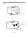
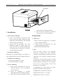
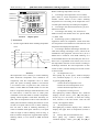
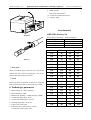
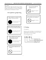
Madell Technology Corp. QHL320A Small-scaled Reflow Soldering Equipment http://www.madelltechcom Dear users, Don not disassemble the equipment by self. Thanks for your support and credit of our company. Please read this manual instruction carefully before installing and operating. If you have any problems, please contact us, we will answer it in time. It may lead to equipment damage. Safe regulations(Important) Don not jam the heat apeture and put anything on the equipment. Please install an air switch with leakage current prevention. It may lead to equipment damage. It may lead to electric shock, fire and physical hurt. Please connect the ground clamp of the power pin with earth reliable. 1. Package ☺Unpacking: Check the items according to the encasement list within package. If any problem occurs or item misses, please contact us as soon as possible. It may lead to electric shock, equipment damage or fire. ☺ Check equipment type If any problem occurs, please switch off and check the equipment, then restart. It may lead to electric shock, and equipment damage . Don not dive hands into fan laminae. It may lead to physical hurt. -1- Madell Technology Corp. QHL320A Small-scaled Reflow Soldering Equipment http://www.madelltechcom 2. Outline Out-smoke-hole Window Handle of drawer Display panel Power switch Picture1 Front View Product Nameplate Product laser identification code Light switch Picture2 Back View -2- Madell Technology Corp. QHL320A Small-scaled Reflow Soldering Equipment http://www.madelltechcom PCB Shelf Picture3 D. 3. Installation 4. Operation ☺ Environment conditions: ☼ Please avoid installing in the place around dust, corrosion gas, damp, leakage rain, high temperature, electromagnetism, and strong RF emission, shaking and rocking. ☼ Please keep the equipment away from flammable, explosive, volatile items, and strong convective air, and keep enough space for operating and servicing that are convenient for maintaining and cleaning. ☺ Before start ☼ Please confirm the supply power is congruous with the product nameplate. ☼ Please connect the grounding wire with grounding equipment reliably. ☼ Please clean the equipment inside. ☺ Start Press the power switch of the equipment, self-check is loading firstly. After self-check, window1 (Picture4) displays “ PASS ” and current temperature later. Window2 (Picture4) displays time “ 00 ”. ☼ [SET] key: sound alarms each press. Setting alert temperature in default temperature curve, the startups segment of cooling (any of 20 segments can be set as cooling startup), and time and temperature of each segment. ☺ Placement conditions: Please place the equipment flatly on a wooden or a steel workbench (please connect to ESD ground line). ☺ Temperature conditions: Environment temperature: 10~30ºC Environment humidity: ≤85%RH ☺ Power conditions: A. B. C. while using PE as a ESD ground line. Please use a plug receptacle of which the rating current is ≥15A for equipment. Please install a single-phase air switch of which the capacity is ≥15A with leakage current protection. Power of equipment is AC220V single-phase three lines with PE protection. Please measure up the grounding resistance, ☼ [Run/Stop] key: sound alarms each press. Setting back, program running and stop. ☼ [◄] Back key: sound alarms each press. ☼ [▲] Increment set key: +1 per press. ☼ [▼] Decrease set key: -1 per press. -3- QHL320A Small-scaled Reflow Soldering Equipment Madell Technology Corp. SMT REFLOW SOLDERING EQUIPMENT Window1 TEMPERATURE/SETPOINT ° C Window2 TIME/VALUE S HEAT ° C RUN RUN SET STOP Picture4 Display panel ☺ Preferences Picture5 Typical PCB reflow soldering temperature curve TEMPERATURE 250 °C heating heating preserving soldering 120s 25s cooling 200 °C 150 °C 100 °C take out PCB 50 °C 360s TIME Picture5 The temperature curve is the key to control soldering effect. Real-time temperature curve should be set congruously with the temperature curve of solder paste. The speed of heating should be set between 1-2°C/s before 160°C. If speed is too fast, on the one hand, it makes SMD and PCB heated too fast that leads to components damage and PCB distorted. One the other hand, it makes the flux of solder paste volatilized too fast that leads to metallic components spilling, which engenders solder balls. Generally, set peak value of temperature 20~40°C more than that of solder paste and reflow soldering time between 10~60 seconds. If set peak value too low or reflow soldering time too short, it leads to soldering deficiently, or results in infusible solder paste. Moreover, if set peak value too high or reflow soldering time too long, it leads to metallic components oxygenated that impacts soldering effects, or even results in SMD and PCB damage. -4- http://www.madelltechcom Reflow soldering temperature curve sets a. According to the temperature curve of solder paste, which is various temperature curve based on metallic content. Please set the reflow soldering temperature curve according to the temperature curve of solder paste offered by the solder paste suppliers. b. According to the material, thicknesses, ply, and dimension of PCB. c. According to the density, size, and color of SMD on PCB, and whether there are special SMD, i.e., BGA, CSP. d. Fast heating system is adopted in the equipment. Please set temperature a little lower than real temperature cause difference exists between real temperature and displayed temperature. e. According to different technologic demands, we offer three heating technologic curves, which can be modulated in the equipment. The first curve (Ln1) is default that is suited for some PCB soldering. It is recommended that users do not modify the first curve. Each curve is segmented in 20 sections; users can set the temperature and time of each section according to technologic demands. The max temperature of each section is 260°C, and the running time of each section is 9999 seconds. (1) Set temperature curve Press [SET] key on the panel, window1 displays “Ln”, window2 displays “1”, “2” or “3” is available by pressing [▲] and [▼]. 1 means the first temperature curve 2 means the second temperature curve 3 means the third temperature curve (2) Set imperative cooling section Press [SET] key, window1 displays “Fn”, window2 displays current section, press [▲] and [▼] to choose any of 1~20 section, in which the cooling start, and this is the end section. After the end section, the equipment alarms. (3) Set temperature alert Press [SET] key, window1 displays “AL”; window2 displays the upper limit of temperature (normal is 240 °C). (4) Factory Test (For manufacturer test) Press [SET] key, window1 displays “DIS”, window2 displays “9999”, press [▲] and [▼] to Madell Technology Corp. QHL320A Small-scaled Reflow Soldering Equipment http://www.madelltechcom starts at the 20th section and is the ending section. Step 3: Continue pressing [SET], window1 displays “AL”, window2 displays the upper limit of temperature. Press [▲] and [▼] to change the number displayed in window2 to 230, which means the equipment alarms when the temperature reaches to 230°C. Step 4: Continue pressing [SET], now window1 displays “DIS”, window2 displays “9999”. Users need not to set in this step. Step 5: Continue pressing [SET], now window1 displays “C01”, window2 displays the temperature value set in the first section. Press [▲] and [▼] to change the value displayed in window2 to 70, which means the highest temperature in the first section. Step 6: Continue pressing [SET], now window1 displays “t01”, window2 displays the time value set in current section. Press [▲] and [▼] to change the value displayed in window2 to 25, which means the temperature will reach to 70°C in 25 seconds. Step 7: Continue pressing [SET], now window1 displays “C02”, window2 displays the temperature value set in the first section. Press [▲] and [▼] to change the value displayed in window2 to 80, which means the highest temperature in the second section. Step 8: Continue pressing [SET], now window1 displays “t02”, window2 displays time value set in current section. Press [▲] and [▼] to change the value displayed in window2 to 15, which means temperature will reach to 80°C in 15 seconds. Step 9: According to step 5 and 6, set temperature and time of 3~19 section refer to attachment1. Step 10: The 20th section is cooling section, in which the temperature cannot be set but time can be. Refer to attachment1; value of “t20” is 120. Step 11: Press [RUN/STOP] to finish the first curve set. modify. (5) Set temperature and time of each section ☼ Set temperature Press [SET] key, window1 displays “C01” (C means temperature, 01 means the first section), window2 displays the temperature value of the first section. Press [▲] and [▼] to modify. ☼ Set time Press [SET] key, window1 displays “t01” (t means time, 01 means the first section), window2 displays the time value of current section. Press [▲] and [▼] to modify. (6) Repeat Step (5) to set other sections. Press [◄] to previous section. Press [RUN/STOP] key to stop setting and back to start. (7) Set temperature and time of cooling section ☼ Set temperature Press [SET] key, check whether the section displaying in window1 is as same as set in Step (2), window2 displays the temperature value which is “00” set in cooling section. Do not modify temperature of cooling section. ☼ Set time Continue pressing [SET] key, check whether the section displaying in window1 is as same as set in Step (2), window2 displays the time value in current section. Press [▲] and [▼] to modify. Press [RUN/STOP] key to stop setting and back to start. Window1 displays the current temperature value, window2 displays time 00 (s). (8) Repeat Step (1) ~ (7) to modify if users need. While re-setting, press [◄] to back. All sets are stored in memory automatically, which is default at next start. Appendix Set typical reflow soldering curve (Curve 1): (Preferences details in attachment1) Step 1: Press [SET] on panel, window1 displays “Ln”, window2 displays: “1”, which means the first temperature curve. Step 2: Continue pressing [SET], now window1 displays “Fn”, window2 displays current section. Press [▲] and [▼] to change the value displayed in window2 to 20, which means the first temperature curve is segmented in 20 sections, the cooling section ☺Load original set Turn off the equipment and shut off the power, then press [RUN/STOP] and [▼] simultaneity and hold until window1 displays “----” and the buzzer phonates, then window1 displays “ PASS ”. Original set loading is finished. Details of original set in attachment1. -5- Madell Technology Corp. QHL320A Small-scaled Reflow Soldering Equipment http://www.madelltechcom ☺Run ☺ Maintain sensor Press [RUN/STOP], now the running indicator light (green) brightens up and heating indicator light (red) brightens up, which means quartz’s tube output. Window1 displays current section and temperature alternately. Window2 displays running time of each section (s1~20, means which section). If user wants to stop, press [RUN/STOP] to stop running, and then all indicator lights turn off. After all sections are finished, the buzzer phonates, while the cooling electromachine is remaining. Window1 displays current temperature inside the equipment. Press [RUN/STOP] to stop phonating, cooling electromachine stops. Press [RUN/STOP] again; the equipment will work from the first section. Suggestions:Please run the equipment to warm up before use it each time. A. During the equipment is running, it is forbidden to modify other temperature curve. B. Do not exceed the soldering area 320*220mm2, while placing the PCB. Please keep PCB flat. C. Please open the drawer slowly to avoid PCB shaking, which make SMD shift. D. Please keep watching when the equipment is running. E. Please do not touch the part exposed in front of temperature sensor. The sensor is located on top of the quartz tube. Please do not strike the probe of the sensor. Please use water-free alcohol tampon wipe it softly to clean. Caution: Do not shift the probe while cleaning. ☺ Check the power Please make sure that the connection of power is tried before start. ☺ Heating fault Please check the quartz tube when the equipment has finished working based on the right temperature curve, solder paste is not yet solidified entirely. If any tube is broken, please change a new one (it should be the same). Caution: Only professionals are permitted to change the quartz tube. Methods: (Picture 6 and 7) a. Please keep the equipment working, observe which quartz tube does not light. b. Please shut down, when the equipment is cooling down, open the drawer, and screw the bolts off on the cover. Open the cover; screw the porcelain cap in both sides of the quartz tube and the nuts. c. Please take out the quartz tube, change the new one by the contrary order of (b). d. Please put down the cover and start, observe the equipment. e. Caution: Please make sure the equipment is cooling, and use a fixture spanner. Please do not damage the insulator. ☺Shut down Shut off the power after work. 5. Maintain It is very important for the equipment to maintain timely. ☺ ☺Clean Turn on power, the equipment does not display or fans do not work After the equipment has been used for a period, there is some volatile matter left on the surface inside, which impact the equipment running. Please clean it. Shut down the equipment; use alcohol to clean inside and outside it. It is forbidden to use strong corrosive. Check the connection of power. If power supply is working, please call professionals for help and support. -6- Madell Technology Corp. QHL320A Small-scaled Reflow Soldering Equipment http://www.madelltechcom 9. Width: 320mm Max PCB: 320*220 mm2 10. Dimension: 490*450*345 mm3 11. Weight: 32Kg Attachnment1 QHL320A Factory Set Picture6 Press [SET] continuously,the panel displays: Ln Fn AL DIS 1 20 230 9999 C01 70 t01 25 C02 80 t02 15 C03 85 t03 05 C04 90 t04 05 C05 95 t05 05 C06 100 t06 05 ☺ Fans Fault C07 105 t07 05 Please shut off the power, open the cover, and check whether the fans strike the equipment. If it exists, please adjust the location of the fans. C08 110 t08 05 C09 115 t09 05 C10 120 t10 05 ☺ Smell C11 125 t11 05 Please check the temperature set that is too high that leads to PCB carbonized, or other stuff leave inside. C12 130 t12 10 C13 135 t13 10 6. Technologic parameter C14 140 t14 10 C15 145 t15 20 C16 150 t16 20 C17 155 t17 25 C18 160 t18 25 C19 205 t19 50 C20 00 t20 120 Picture7 1. 2. 3. 4. 5. 6. 7. 8. Rated voltage: AC 220V (with PE) Rated frequency: 50Hz Rated power capability: <3.3KW (Average=1.0KW) Temperature upper limit: 260℃ Environment temperature: 10~30℃ Working temperature: 40~230℃ Light inside: 220V/35W PCB automatic soldering time: 4~6min Continuous working time: 48H -7-