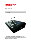
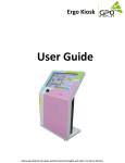
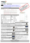
1
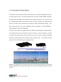
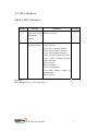
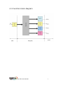
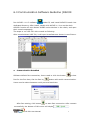
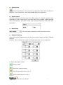
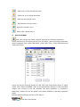
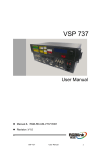
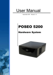
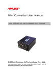
Series
Split Panel User Manual
Document No:RGB-RD-UM-V320E001
VSP 320
RGBlink Science & Technology Co., Ltd.
The pictures and data in the user manual are consult only, if there is
fluctuation, according to the real object please!
z
Contact Us
Headquarter: S603 Weiye Building Torch Hi-Tech Industrial Development Zone
Xiamen,Fujian Province, P.R.C
Shenzhen office: Room A05, Floor 4, Building 24, Industry factory Nanshan
Science & Technology Park, Shenzhen, Guangdong Province, P.R.C
Tel: +86-592-5771197
Fax:+86-592-5771202
E-mail:[email protected]
http://www.rgblink.com
Revision
Format
Time
ECO#
Description
Principal
1.0
2009/08/01
0000
release
Lisa
2009/08/15
0032
Add Appendix and Communication
1.1
Software Guideline
1.2
2009/08/17
0045
1.3
2009/10/08
0052
1.4
2009/12/11
0062
Add screen parameter
DVI conection doesn’t support hot
plugging.
Upadate toggle indication and
Lisa
Lisa
Lisa
Lisa
communication software guideline
1.5
2010/01/25
0072
How to save
Lisa
Content
Contact Us
Revision
1.0 Function Description .............................................1
2.0 DVI Interface .......................................................2
3.0 Toggle switch and LED indication ............................2
3.1 Toggle switch...................................................2
3.2 LED Indication .................................................3
4.0 Function block diagram .........................................4
5.0 Specification/parameters .......................................5
6.0 Communication Software Guideline (RS232) ...........6
1.0 Function Description
VSP 320 has one DVI input and four DVI output, it can be as a distribution device
or split screen device. The input signal source include: HDMI (HDMI interface,
DVI protocol) and PMC (as a module on the video processor). So it can be used
as a independent device, and also can be used as a module. As a distribution
device, the max input resolution can support 1280*1024*60Hz (VESA);As a
split screen device, the max supported input resolution is 1024*768@60 ,
1024*768@75 and 1280*768@60.
VSP 320 can control by toggle switch or RS232 communication. Toggle switch
can implement horizon 4 sections, horizon 2 section, vertical 4 sections, vertical
2 section four split screen mode. And it also can be used a module of AVDSP,
implement many split screen modes which control by I2C.
The control modes
priority is I2C, RS232 and then toggle switch.
Remark: This legend is only used to describe how the video processor will work with
VSP320, please refer to video processor user manual for detail operation of video
control.
VSP 320 User Manual
1
2.0 DVI Interface
Table 3 is the position definition of DVI output and its image segment.
Table 3 the relation of DVI interface and output image.
DVI1
DVI2
DVI3
DVI4
Split 4 section
Top left
Top right
Down left
Down right
Horizon split 2 section
Semi-left
Semi-right
Semi-left
Semi-right
Vertical split 2 section
Semi-top
Semi-down
Semi-top
Semi-right
Horizon split 4 section
left1
Left2
Left 3
Left 4
Vertical split 4 section
top1/4
Mid-top1/4
Mid-down1/4
down1/4
Remarks:
1) The DVI interface near the power interface is signal input.
2) DVI1~DVI4 are the four DVI output.
3) This Connection does not support hot-plugging.
3.0 Toggle switch and LED indication
3.1 Toggle switch
When resolution is 1024X768@60, please refer to the following table for the
detail default setting:
Mode
Toggle switch
1
2
3
4
Mode 1
directly
on
on
on
On
Mode 2
4 section
on
on
on
off
Mode 3
Horizon 2section
on
on
off
On
Mode 4
Vertical 2section
on
on
off
off
Mode 5
Horizon 4section
on
off
on
On
Mode 6
Vertical 4section
on
off
on
off
Remark:Users can change the DIP switch setting by host computer. Users can
refer to Page 8 for the details.
VSP 320 User Manual
2
3.2 LED Indication
Table 1 LED Indication
Number
1
Function
Indicate
if
Indication
the
work state of the
equipment
Remark
light- normal;
flicker- abormal;
is
normal
[2..4]
Work
state
or
equipment error
Ordinary work state:
"000"-directly;
"001"-split 4 section screen
"010"-horizon split 2 section;
"011"-vertical split 2 section;
"100"-horizon 4 section screen;
"101"- split 4 section screen,
input test data.
other-reserve
Error indication:
“000”-no DVI input
“001”-DDR
SRAM
unable
to
initialization
other-reserve
Remark:
LED extinguish is 0,LED light up is 1
VSP 320 User Manual
3
4.0 Function block diagram
VSP 320 User Manual
4
5.0 Specification/parameters
DVI Input
Number of Inputs
1
Connector
HDMI Type A
Supported Standards
1024×768×60Hz,1280×768×60Hz
Signal Level
TMDS pwl,single pixel input,165MHz bandwidth
Standard
DVI 1.1
DVI Output
Number of Outputs
4
Connector
HDMI Type A
4096×768×60Hz
2×2048×1152×60Hz
2×1024×1536×60Hz
Supported Standards
1024×3072×60Hz
5120×768×60Hz
2×2560×1152×60Hz
2×1280×1536×60Hz
1280×3072×60Hz and user define
Signal Level
TMDS, 165MHz bandwidth
Function
Router
1 in 4 out
Spliter
Support 4 pictures splite by any modes
Extras
Communication
RS232
Power Supply
85-264V 2A IEC-3
Working Environment
0°C~45°C
Stored Environment
10% to 90%
Product Warranty
1year
VSP 320 User Manual
5
6.0 Communication Software Guideline (RS232)
Run AVDSP 1.1.0.2 software
inside CD, and install AVDSP Console into
dedicated directory. After install, double click AVDSP 1.1 icon on the desk.
AVDSP Console will auto detect AVDSP series devices in the chain, and open
their console seperately.
The steps to run VSP 320 with console as following:
After console detect VSP 320, it will open its software as shown in next Picture.
z
Communication Establish
to close
Software default Port connection, Users need to click the button
Port for the first time, Set the Port by
button with serial communication.
Users need to select between serial port and baud rate.
After Port setting, click button
to start Port connection. After connect
successfully, the bottom of left corner will display
VSP 320 User Manual
.
6
z
Synchronize
Click the Sync button, can synchronize configuration data inside hardware by
software. At the same time, could read EPROM data from equipment.
z input source
VSP 320 contains one DVI input,four DVI output, it can be used as Video
distributor or sub-screen device. Two input Video source:HDMI(HDMI interface
with DVI protocol) and PMC(used as an output module of VSP 618 Video
processor).
z
Resolution
,fill in the input resolution in the drop-down menu.
z Channel Setting
Users can adjust displacement of each port output image through “Channel
Setting”.
Remark:Users change the width and height parameter is not suggested.
4. Select split panel modes
,Router mode
,Split into 4 panels mode
,Split Horizontal direction into 2
,Split Vertical direction into 2
VSP 320 User Manual
7
, Split into 4 in Horizontal direction
, Split into 4 in Vertical direction
, Split top Horizontal into 4
, Split bottom Horizon into 4
,Split left Vertical into 4
,Split right Vertical into 4
z
Save to EPROM
User can change the factory default settings by following operation.
Firstly, select input resolution which from DVI input, users can select resolution
device supports from 1024*768*60Hz, 1024*768*75Hz, 1280*768*60Hz and
1440*900*60Hz.
Users can set all working modes of VSP 320 from drop-down menu of splite
mode, click “Save to EPROM” after all the parameters setting. If the command
output very quickly in the log window, the save operation is successful.
Otherwise, please turn off the power and restart VSP320 to do save operation
again.
System default settings shown as the figure:
VSP 320 User Manual
8
Remark:
1.If you need to change the output resolution, you can just select the desired
resolution in the drop-down menu, with the above steps can be set up.
2. When EPROM under the resolution saved successfully. Users can view the set
by sync operation
。
3. System status, system control, input and output, parameter setting under
the advanced setting is set only by certification engineers, users do not need to
set up.
VSP 320 User Manual
9