1
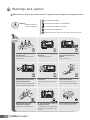
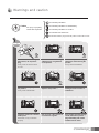
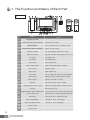
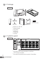
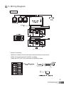
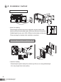
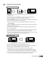
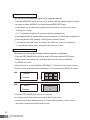
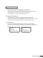
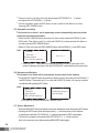
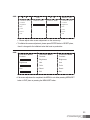
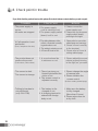
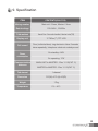
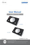
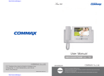
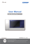
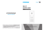
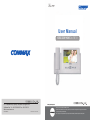
User Manual
VIDEO DOOR PHONE CAV-70B,71B
513-11, Sangdaewon-dong, Jungwon-gu, Seongnam-si, Gyeonggi-do, Korea
Int’l Business Dept. Tel. : +82-31-7393-540~550 Fax. : +82-31-745-2133
Web site : www.commax.com
PM0270B00010
Printed In Korea / 2011.10.104
•
• Thank
Thank you
you for
for purchasing
purchasing COMMAX
COMMAXproducts.
products.
•
• Please
Please carefully
carefully read
read this
this User’s
User’sGuide
Guide(in
(inparticular,
particular,precautions
precautionsfor
forsafety)
safety)before
beforeusing
usingaaproduct
productand
andfollow
follow
instructions
instructions to
to use
use aa product
productexactly.
exactly.
•
• The
The company
company isis not
not responsible
responsiblefor
forany
anysafety
safetyaccidents
accidentscaused
causedby
byabnormal
abnormaloperation
operationof
ofthe
theproduct.
product.
Table of Contents
1. The Function and Name of each Part
2
2. Features and Main Function
3
3. Package
4
4. System Layout
4
5. Wiring Diagram
5
6. Installation Method
6
7. Operating Description
Visitor Call & Monitoring
Interphone Function
Burglar Function
Review Function
Product Setting
7
8. Check Point in Trouble
12
9. Specification
13
Warnings and caution
Make sure to follow the instructions to prevent any danger or property losses.
It indicates prohibition.
Warning
It indicates prohibition of disassembly.
Death or serious
injury is expected.
It indicates prohibition of contact.
It indicates dos and don’ts.
It indicates that the plug should be pulled out from the socket.
Do not put the plug in the socket
simultaneously.
It may generate abnormal heat
or cause a fire.
Do not connect to other products
while in use.
It may cause breakdown.
Do not forcibly bend the cord or
put a heavy object on the
product.
It may cause a fire.
Do not use water, thinner or a
detergent used to wash oil products
when you wash the exterior.
Make sure to wash it by using a dry cloth to
prevent any breakdown or electric shock.
Do not install the product in a
humid place.
It may cause an electric shock or
a fire.
Do not forcibly pull out the
cord from the socket.
If the cord is damaged, it may
cause a fire or an electric shock.
Do not put the plug in the
socket with a wet hand.
It may cause an electric shock.
Do not disassemble, repair or
modify the product.
It may cause a fire, an electric shock
or an injury due to malfunction of the
product.
Do not use AC circuit breaker.
It may cause an electric shock.
Warnings and caution
It indicates prohibition.
Caution
It indicates prohibition of disassembly.
An injury or property
losses are expected
It indicates prohibition of contact.
It indicates dos and don’ts.
It indicates that the plug should be pulled out from the socket.
If the socket holes are larger
than normal, do not put the
plug.
It may cause an electric shock
or a fire.
Make sure that dust or foreign
substances are not gathered
on the product.
Make sure to prevent foreign
substances from entering the
product.
It may cause a breakdown.
Do not put a heavy object on
the product.
It may cause a breakdown.
Do not disassemble or give an
impact to the product.
Avoid direct rays of the sun or
heating devices at a time of
installation.
Install the product in a flat and
stable place.
Otherwise, it may not function
properly.
Pull the plug if the product is
not used for a long time.
If the product generates strange
sound, make sure to pull the
plug immediately and contact
Commax service center.
1. The Function and Name of Each Part
▶ function
No.
Details
Name
1
Charging terminal
2
Volume for call volume control
3
Monitor button
4
Volume for talk volume control(H/F)
5
Interphone button
Talk by interphone between the rooms.
6
Menu/Set button
Burglar, Room ID, Interphone receiving rejection and RF ID are set.
7
Up button
Up direction key
8
Left button
Left direction key
9
Down button
10
Power supply switch
11
Enter button
Execution button
12
Right button
Right direction key
13
Talk button
Talk in calling over the door and interphone.
14
Open button
Operate on Door release of door camera.
15
Record button
Record the screen of camera.
16
Speaker
17
Chargingmode power lamp
18
Handset
Control the call volume.
View the screen by door camera or talk.
Control the talk volume.
Down direction key
Control the power supply of product.
Talk voice and call voice is spoken.
Display that charging condition of handset is normal.
Wire type(CAV-71B)
19 Burglar/Automatic video recording lamp Red lamp in burglar set, Green lamp in automatic video recoding is flashing.
2
Supply power source of product. (AC100V-240V Free-voltage)
20
Power source code
21
Microphone
22
Input terminal(INPUT)
23
Output terminal(OUTPUT)
Terminal for out in connecting.
23
24
Output
Handset
terminal(OUTPUT)
Speaker
Terminal for out in connecting.
23
25
OutputHandset
terminal(OUTPUT)
mike
Terminal for out in connecting.
Send the voice in hands free talk.
Terminal for input in connecting.
2. Features and main Function
1. Features
7” WIDE TFT-LCD
● Suface mount type installation method
● FREE VOLTAGE power supply
● Menu control by on screen display(OSD)
● RF(2.4GHz) Wireless handset
●
2. Main function
Interphone call and talk function
● Image storing (128 cut) function
● Burglar function
● Door Open Function
● CCTV interworking
● 4 Door units & 20 Room station connectable.
●
3
3. Package
24
3
1
2
5
4
6 8 9 11 13 14 15
7
10 12
16
▶ images
Connector 6P (2EA)
●
Moniter unit : CAV-71B
●
Wireless Handset
●
User manual
●
Wall Bracket
●
Fixing Screw
Connector
4. System Layout
●
▶ images
Master
100m(at Cat.#5)_6wire
●
●
4
The number of door camera connection: 4 units (Max.)
*CCTV Camera connectable
The number of household monitor connection: 20 units (Max.)
25
5. Wiring Diagram
▶ images
Room unit 1
*
Room unit 2
*
NEXT ROOM UNIT
●
Notes for connecting
-Maximum number per line from the slave connection terminal of main unit is 5.
-Please connect wiring terminal carefully on polarity.
-Please use UTP (CAT. 5) for cable and 14~24AWG for others.
5
6. Installation method
▶ Installation method of monitor
●
Notes for installing
direct ray of the sun and nearby heater, which may influence on the product.
145cm
-Please keep the product away from a magnetism, severe moisture, and
-Suitable height for main unit is 1450~1500mm from the bottom to the screen.
-Please arrange the handset after installation completed.
▶ Installation method of camera (at DRC-4CH)
●
Notes for installing
-Please keep the product away from a direct ray of the sun or strong reflected light.
(You may not get clear screen quality.)
6
7. Operation Description
1. Visitor call & monitoring
Press Call button on camera to see the visitor’s look with chime sound from the
household monitor.
● If you want to talk, press the TALK button to communicate in hands-free mode.
● If you hold up handset, communication is available by handset.
● Press the MONITOR button to see condition of the door in standby state, and press the
RIGHT ( ▶ ) button to see the screen of next camera.
▶ At that time, the camera is not set as connecting with DIP S/W of main unit, that
channel is passed.
● Pressing the OPEN button while talking or monitoring over the camera, then close the
contact relay for about 4 seconds.
● Pressing the REC./IMAGE button while talking or monitoring over the camera, then
store 1 cut at that moment.
● Press the MONITOR button to end while talking over the door camera by hands-free,
put down the receiver to end communication while talking over handset.
● When visitors call simultaneously at more than 2 cameras, chose a camera you wish to
talk by using the UP/DOWN direction and press the talk button.
●
2. Interphone function
●
●
●
●
This function is to call or to communicate the other room.
Press the INTERPHONE button to display ROOM ID on the screen.
Place an arrow to call desired ROOM using UP/DOWN button and press the ENT button,
then you can hear call sound (melody) in the responding ROOM.
Press the TALK button or hold up the handset to communicate each other.
▶ Own ROOM number is written in parenthesis and cannot be called. Ex.: [Room 1]
▶ If Room ID set to reject interphone call receiving is called, “REJECT CALL” is displayed.
●
●
In case of calling a room number without a video phone, “Unconnected Device” is displayed in OSD.
In case the line is busy with another device, “Interphone Busy” is displayed.
7
3. Burglar function
This function is to execute burglar set by magnetic switch.
●
Press the MENU/SET button and set Yes(Y) or No(N) with the right(¢¹) button in burglar
set mode, and then the MENU is out after pressing MENU/SET button.
▶ It is available only in case that the magnetic switch connected to the main unit is closed.
(Holding time: 60 sec)
▶ If ‘Y’ is selected, red lights in all monitors is flashing simultaneously.
●
If the burglar function is required after the set is completed, a holding time is needed and
a siren sounds with OSD message. (Holding time to release: 30 sec)
▶ In release, press the ENT button according to the OSD menu, restore is available only
in case that the magnetic switch connected to the main unit is closed.
4. Review function
This function is to see the stored screen by manual or automatic.
●
●
Press the REC./IMAGE button and then enter into Review mode with ENT button.
Stored screens are showed per 6 screens and you can see 6 cuts in order with
the RIGHT(▶) button.
●
Place an arrow on 1 screen with the UP/DOWN(▲,▼) button to review it per 1 screen.
●
Every 1 screen is reproduced and showed per 1 cut in order with the RIGHT(▶) button.
OSD:
1 sereen
▶ 6 sereen
OSD:
▶ 1 sereen
6 sereen
●
Press the REC./IMAGE button and menu out finish
▶ It is showed from the last stored screen and all 128 cuts are stored.
▶ Please be noted that an additional screen to be stored after completion of 128 cut stores,
the screen is removed from the first stored screen.
8
5. Product setting
5-1. Room ID set
Please set Room number to be designated in Interphone Call.
● Switch to Room ID set mode with MENU/SET button. Press the ENT button after
placing an arrow on desired Room number with UP/DOWN(▲,▼)
or LEFT/RIGHT(◀, ▶)button, and then the Menu is out.
5-2. Interphone Call Rejection set
It is set when you don’t want to receive the Call from the other Room.
● Switch to Inter. Reject call mode with MENU/SET button and select Yes (Y) or No (N)
with RIGHT(▶) button, and then the MENU is out after pressing ENT button.
5-3. Time Adjustment
It is set to store the time when the screen is stored in the image memory.
●
Switch to Time set mode with REC./IMAGE button with the DOWN (▼) and ENT button.
OSD:
Review
set
Auto record
Del. Whole memory
▶ Time
09/mar/06 12:30:00
▲
Day set :09
● Complete: ENT
9
Place an arrow(▲) at the point to be adjusted with LEFT/RIGHT(◀, ▶) button
and adjust with UP/ DOWN(▲,▼) button.
● A set is completed, press the ENT button to store, and then the Menu is out after
pressing REC. IMAGE button.
●
5-5. Automatic recording
This function is to store 1 cut of momentary screen automatically when the visitor
press the Call button at the door.
● Press the REC./IMAGE button and enter into Auto record mode with DOWN(▼) and
ENT button. Then Select yes(Y) or no(N) with RIGHT(▶) button and then the Menu is
out after pressing REC./IMAGE button.
●
Switch to Time set mode with REC./IMAGE button with the DOWN (▼) and ENT button.
OSD:
▶
Review
Time set
▶ Auto record
Del. Whole memory
Auto rec Y
If the set is in “Y”, automatic recording lamp(Green) located in upper part of the
product is flashing. (the lamp of the other ROOM UNIT is also flashing at the same time)
5-6. Stored screen Deletion
This function is to delete all of unnecessary screen stored in the memory.
●
Press the REC./IMAGE button and switch to Whole memory del mode with the DOWN(▼)
and ENT button. Then select yes(Y) or no(N) with RIGHT(▶) button. All memory contents
are deleted after pressing ENT button.
OSD:
Review
Time set
Auto record
▶ Del. Whole memory
Del.Whole memory Y
Push the enter
▶ The Menu is out after pressing REC./IMAGE button.
5-7. Screen Adjustment
Press the MENU/SET button and switch to the screen adjustment mode after pressing ENT button.
Pressing the ENT button show the finger picture(☞), and then place it to be required
in adjustment mode with UP/ DOWN(▲,▼) button and press the ENT button again.
● The level is increased or decreased with LEFT/RIGHT(◀, ▶) button and turn
back to the previous menu after pressing MENU/SET button again.
●
●
10
OSD:
▲ ▼
CONTROL MENU
Contrast
Brightness
Hue
☞Color
ENT
◀ ▶
CONTROL MENU
CONTROL MENU
Color
Color
Reset
MENU / SET
CONTROL MENU
Contrast
Brightness
Hue
☞Color
Reset
Exit
▶
●
Exit
Please adjust other screen adjustment on the same way.
To initialize the screen adjustment, please press ENTER button in RESET place,
then it is changed to the initialized value that is set on production.
OSD:
CONTROL MENU
CONTROL MENU
CONTROL MENU
Contrast
Contrast
Contrast
Brightness
Brightness
Hue
Hue
Color
Color
☞Reset
Reset
Brightness
Hue
Exit
●
☞Exit
If all screen adjustment is completed, the MENU is out either pressing MENU/SET
button in EXIT place or pressing the MENU/SET button.
11
8. Check point in trouble
If you think that the product has trouble, please first check below contents before you ask a repair.
Troubles
●
●
●
The power supply is
not on.
All works are stopped
A Call operation is not
performed.
(Door, Interphone function)
●
The product does not
produce the sound.
(Call volume, Talk volume)
●
●
●
12
The screen is dark.
The screen is strange.
Talking by handset is
not performed.
(only CAV-70B)
Check Point
1.The power supply
code is missing or not.
2.The power supply switch
(down) is off or not.
Actions
1. Please connect the
power supply cord
2. Please turn on the power
supply switch (down)
pushing to the right.
1.The wiring between other
1. Please refer to connection
units is connected correctly
related page and manage.
in good order or not.
2. Please connect correctly
to the terminal.
2. The wiring is missing or not.
3. Please refer to Room id
3. A Room id is set or not.
setting related page.
1. A sound volume lies
in minimum or not.
1. Please adjust the sound
volume properly turning
to the right, as you want.
1. There is a strong reflected light behind the
visitor or not.
2. The screen control is
adjusted correctly.
1. Please change the angle
of camera lens.
2. Please initialize the
screen control.
1. The battery is discharged or not.
2. A charging terminal is
stained with foreign
body or not.
1. Make sure the battery
is fully charged.
(More than 5 hours)
2. Please wipe clean on
a dry cloth.
(Refer to setting related page)
9. Specification
ITEM
CONTENTS(CAV-71B)
Wiring number
Main unit: 6 lines, Master: 6 lines
Rated voltage
100-240V~, 50/60Hz
Talk method
Hands-Free: Voice switch method, Handset: wire(71B)
Display unit
17.78Cm(7”) TFT-LCD
Call sound
Power
consumption
Door (individual door): ring electronic chime 3 sounds
twice repeatedly, Interphone: electronic melody sound
On standby: 4.4W
On operating: 17W
Communication
distance
MAIN UNIT to MASTER : 20m/ Ø0.5(CAT. 5)
MASTER to MASTER : 20m/ Ø0.5(CAT. 5)
Talk channel
1 channel
Dimension
315(W) x175 (H) x53(D)
Weight
1.7kg
Temperature
0℃~ 40℃
13
Memo
14