1
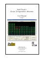
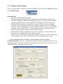
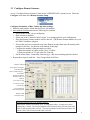
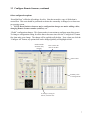
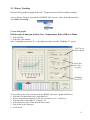
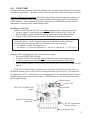
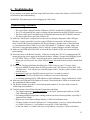
SafeTrackTM
Grain Temperature Monitor
User Manual
Version 2.7
3-10-2008
Safe-Grain, Inc.
3530 Irwin Simpson Road
Mason, OH 45040
800-659-8250
www.safegrain.com
Technical Support:
Phone: 513-398-2500
E-Mail: [email protected]
Copyright Information
Copyright © 2008 Safe-Grain, Inc. All rights reserved.
The information contained in this manual and the accompanying software programs are copyrighted and all rights
are reserved by Safe-Grain, Inc. Copying, duplicating, selling, or otherwise distributing any part of this product
without the prior consent of an authorized representative of Safe-Grain, Inc. is prohibited. All brands and product
names in this publication are registered trademarks or trademarks of their respective holders.
Information furnished by Safe-Grain in this manual is believed to be accurate. Safe-Grain makes no warranty, express, statutory, implied or by description, regarding the information set forth herein. Safe-Grain reserves the right
to change specifications at any time and without notice. Safe-Grain, Inc. reserves the right to make periodic modifications of this product without obligation to notify any person or entity of such revision. Safe-Grain’s products are
intended for use in normal commercial applications. Applications requiring extended temperature range or unusual
environmental requirements are specifically not recommended without additional testing for such application.
Please contact Safe-Grain if you encounter any problems or have any questions at 1-800-659-8250 or e-mail at
[email protected].
TABLE OF CONTENTS
1.
Overview
1.1 SafeTrack Overview ............................................................................................................1
1.2 SafeTrack Quick Start Guide ...............................................................................................2
2.
Software Installation
2.1 Installation ...........................................................................................................................3
2.2 Removal ...........................................................................................................................3
2.3 Remote Access .....................................................................................................................3
3.
Using SafeTrack
3.1 Current Data (Main page) ....................................................................................................4
3.2 Configure System Settings...................................................................................................5
3.3 Configure Remote Scanners ................................................................................................6
3.4 Scan Data ...........................................................................................................................9
3.4.1 Demonstration Mode ..................................................................................................9
3.4.2 Communications Diagnostics ...................................................................................10
3.4.3 Monitor Window.......................................................................................................10
3.5 History Tracking ................................................................................................................11
3.6 Reports
.........................................................................................................................12
4
Hardware
4.1 General Hardware Specifications ......................................................................................13
4.2 SafeLink Radios .................................................................................................................14
4.3 Remote Scanners................................................................................................................16
4.3.1 COM Card.................................................................................................................17
4.3.2 Cable Card ................................................................................................................18
4.3.3 Backplane..................................................................................................................19
4.3.4 Power Supply ............................................................................................................20
5
Remote Access Guide ..................................................................................................................
5.1 Networks, Addresses and Security ....................................................................................21
5.2 Configuring SafeTrack for a Remote USer .......................................................................22
5.3 SafeTrack Server ................................................................................................................23
5.4 Configuring SafeTrack Server ...........................................................................................24
5.5 Network and Firewall Tips ................................................................................................24
6
Troubleshooting .......................................................................................................................25
7
8
FCC Notices and Requirements (900MHz radios only) ..........................................................28
CE Approval (868MHz and 2.4 GHz radios only) ..................................................................29
i
1.
SafeTrack Overview
1.1
System Overview
The SafeTrack Grain Temperature Monitoring System leads the industry in providing the
features you need, with easy to use software and hardware, in a cost effective package. To get the
most from your system please read this manual before starting.
The following diagram is an overview of the SafeTrack system.
In a typical SafeTrack installation each bin will have:
• Temperature cables installed in the bin.
• A Remote Scanner mounted on top of the bin.
• The Remote Scanner will have one Cable Card per temperature cable.
• A Client radio for transmitting data to the SafeTrack PC.
• 120VAC (or 12VDC) and Earth-ground for powering the Remote Scanner.
The SafeTrack PC will have:
• SafeTrack software installed on the computer (MS Excel required for reporting).
• A Server radio for receiving data from each bin.
• An RS232-to-RS485 converter plugged into a serial port or USB port on the computer.
• A 12V wall mount power supply plugged into an outlet to power the converter and radio.
For remote operation of SafeTrack over a network or the Internet:
• The server PC will run a small SafeTrack Server program.
• The remote user will connect over the network/internet instead of through a COM Port.
Client Radio
Data A
Data B
B A
LINK
POWER
12 VDC IN
0V IN
-+
Server Radio
DATA
Data A
Data B
B A
LINK
POWER
12 VDC IN
0V IN
-+
S afeT ra ck S oftw are
DATA
TC CARD
TC CARD
TC CARD
TC CARD
TC CARD
TC CARD
TC CARD
TC CARD
TC CARD
TC CARD
TC CARD
12 0V B A SH
TC CARD
x
CHAIN
COM CARD
EG 0V 12 5V
DC Power IN To Radio/PC
GND
DAT
PWR
A
DATA
B
DAT
PWR
C o m p uter
C O M P o rt
(or U S B P o rt)
S plice
C om pa rtm e n t
100-240VAC (47-63Hz)
and Earth-GND
2A
HOT
COM
E GND
RS-485
12
C
C
5
5
N.
L
RS-232
T em perature
C a b le s
fro m bin .
T D -A
T D -B
GND
1 2V
ECHO O FF
R S 2 3 2 -R S 4 8 5
Isolated C o nverter
12VDC
W a ll
A da pter
Remote Scanner
1
1.2
Quick Start Guide
The following provides a brief overview of the steps to install and configure SafeTrack.
Hardware installation to be performed by a qualified technician:
1. The Factory will install one Cable Card per temperature cable in the Remote Scanner.
- The Cable Card address is set to match the cable numbers as labeled by Safe-Grain.
- The Remote Scanner number will be set by using the COM CARD Address jumpers.
2. Install the Remote Scanner at the top of each bin. Place in shade if possible.
3. Splice each Temperature cable to the pigtail of the Cable Card (match the cable number to
the Cable Card number) using the supplied crimps, or the plug-n-play connectors if supplied.
4. Attach 110VAC and Earth Ground to the terminals in the Remote Scanner power supply.
WARNING: Failure to attach a solid earth ground voids all warranties.
Do not install SafeTrack near sources of high RFI or EMI noise (interference).
5. Radio systems: Mount the Client radio making sure it has line-of-sight with the Server radio.
Use 4-conductor data cable (Belden 8723) to connect the radio to the Remote Scanner.
6. At the computer: Attach the RS232-to-RS485 converter to an available COM/USB port.
7. Wire the Server Radio to the 232-485 converter.
8. Plug the supplied 12VDC power supply into a wall outlet and plug it into the converter.
Configuring SafeTrack:
1. Install the SafeTrack software on the PC. Start the SafeTrack software and configure it for the
correct COM Port. To do this click the Configure menu then click System Settings. If using a
USB-to-Serial converter be sure to select the COM port that the USB drivers have set up.
2. Configure SafeTrack for the number of bins and temperature cables:
To do this click the Configure menu, then click Remote Scanner Setup.
• Enter the total number of bins that SafeTrack will monitor.
• Start with the first bin and enter the following for each:
1. Enter the bin name.
2. Click “Common Layouts” and choose one as a starting point for your configuration.
3. Enter the Remote Scanner number (set by the COM CARD address) for this bin.
4. If more than one bin is connected to the same Remote Scanner then also enter the
starting cable number (Cable Card address) for this bin.
5. Enter the number of thermocouples per cable:
14
15
- Enter the number of cables for each “ring” of cables.
13
5
16
- Enter the number of TCs-per-cable for that ring.
4
6 M A N -H A T C H
6. Select the structure type and alarm limits for the bin.
12
1
7
7. Select the commodity for this bin.
11 3
2
• Repeat these steps for each bin.
8
• Save the changes then click Done.
10
9
Cable numbering is clock3. Test the system by Scanning new data: click the Scan Cables
wise from the man-hatch.
button on the Main screen:
• Select what you want to scan: All Bins, One Bin or just One Cable. Select One Cable for now.
• Click Temperature, OHMs or Both for the type of data you wish to scan. Select Temperature.
• Click the Scan Now button.
• Save the data when finished.
2
2.
Software
Installation and Removal
SafeTrack system requirements:
• Microsoft® Windows® Me, 2000, XP (SP2), or Vista (requires Admin rights to install).
• SVGA color monitor; minimum 1024x768 screen resolution.
• Microsoft Excel® is required for creating and viewing reports.
• A network connection is required for remote network/internet scanning.
2.1
Installation
Run Windows Update and install all critical Windows updates prior to installing SafeTrack.
It is generally suggested to create a Windows Restore Point before installing any new software.
Insert the SafeTrack Installation CD to automatically start the installation routine. If it does not
run automatically then browse to the CD and double-click SETUP.EXE.
1.
2.
3.
4.
Click Next on the first screen.
Verify your Company and Location then click Next.
Click Next to accept the default installation setting on the following two screens.
Click Finish to complete the installation.
Upon completion a SafeTrack icon will be placed on the Desktop, double-click it to start the
SafeTrack program.
You must configure SafeTrack for your environment before using it. See Chapter 3.
2.2
Removal
To remove SafeTrack from your system:
1.
Backup any Configuration (.ini files), Settings, Log, and Data files prior to proceeding.
1.
Open Windows Control Panel.
2.
Double-click the “Add or Remove Programs” icon.
3.
Click “SafeTrack ”.
4.
Click Change/Remove.
5.
Select Automatic Uninstall.
6.
Click Finish.
Your DATA files will remain on the PC. To completely remove these files delete the SafeTrack
folder which is located in the Safe-Grain folder under “Program Files” on C drive. Note that
Reports by default are saved in the “SafeTrack Reports” folder under My Documents. Delete the
SafeTrack Reports folder to permanently remove all reports.
2.3
Remote Access
SafeTrack includes SafeTrack Server which provides remote access to users via the network or
Internet. See Chapter 6 for details.
3
3 Using SafeTrack
3.1 Current Data (Main screen):
The Current Data screen shows the most recent Temperature, Rate-of-Rise, and Ohms readings and
clearly indicates any alarm conditions. All other SafeTrack features including configuration screens
are accessed from this main screen.
To view data:
1. Select the Bin you wish to view.
2. Click “Data Type” to view the current Temperature, Rate-of-Rise or Ohms data.
Menu options
Temperature
alarms.
Scan new
data.
Click the type
of data you
wish to view.
Statistics for
the data you are
viewing.
Select the bin
you wish view.
Current
settings for
this bin.
View
previous
scans.
Menus:
The following menus are available from the CURRENT DATA screen. They are explained later in
this manual.
4
3.2 Configure System Settings
Access “System Settings” from the the Current Data (Main) screen: Select the Configure menu then
select System Settings:
System Settings:
• Enter your Facility Name and Location.
• Select the computer COM port used for communicating with the Remote Scanners. The
COM Port configured by Windows will highlight in green. To see details on the COM Ports
configured in Windows select “Open Windows Device Manager” from the Tools menu.
• If automated daily scanning is to be performed, click the “Enable Daily Auto Scanning”
check-box. Set the time of day to perform the automated scanning. Check “Create Report
after Auto-Scan” to automatically run a report (All Bins, all data) as soon as the Auto-Scan is
completed. Check “Include Ohms...” if you wish Ohms data to be scanned and reported.
• Select the units (Fahrenheit or Celsius) for temperature readings.
• Enabling “Password protect configuration screens” will prompt for a password when someone tries to enter a configuration screen or delete a log file.
• “Delete Log File” will delete the current System and Error log files. Note that a backup copy
is always automatically created. Deleting the Log files is recommended once a year.
NOTE: Configuration files are NOT overwritten during a software upgrade.
Configuration Report: To create a Configurations Report select the Report menu then select Create
configuration Report. The file is created in the current reports folder, the default reports folder is the
“SafeTrack Reports” folder under “My Documents”.
5
3.3 Configure Remote Scanners
Access “Configure Remote Scanners” from the the CURRENT DATA (main) screen: Select the
Configure menu then select Remote Scanner Setup:
Configure the number of Bins, Cables and other settings:
1. Enter the total number of Bins that SafeTrack will monitor.
2. Start with the first Bin and enter the following for each Bin:
• Select the Bin # that you are configuring.
• Enter a name for that bin.
• Select one of the “Common Cable Layouts” as a starting point for your configuration.
• Enter the Remote Scanner number used for this bin. (The Remote Scanner number is set via
its COM Card address jumpers)
• If more that one bin is connected to the same Remote Scanner then enter the starting cable
number for this bin. See the note at the bottom of this page.
• Configure the number of thermocouples per cable:
1) Enter the number of cables in each “ring” of cables.
2) Enter the number of TCs-per-cable for each ring.
• Set the Alarm limits, Commodity, Structure type, and Auto-scanning option for the bin.
3. Repeat these steps for each bin. Save Changes then click Done.
Number of Bins.
Select Bin to configure.
Enter Bin name.
Pick a common layout.
# Of Cables.
Remote Scanner #.
Starting Cable Card
Address.
# of Cables in ring
# of TCs per cable
in each ring.
Layout showing
cable configuration.
Disable a bad
or unused Cable.
Attaching multiple bins to one Remote Scanner:
Each Remote Scanner can monitor up to 32 temperature cables. Example of two bins
each having 11 cables: The first bin attached to this Remote Scanner will start with Cable
Card #1 and end with Cable Card #11. The next bin attached to this Remote Scanner will
start at Cable Card #12 and end with Cable Card #22.
6
3.3 Configure Remote Scanners, continued
Other configuration options:
“Reset Bin Data” will delete all readings for a bin. Note that an archive copy of all the data is
created first. This reset should be performed each time the commodity is changed, or at least once
per growing season.
NOTE: Reset bin data whenever major configuration changes are made: adding cables,
changing Remote Scanner number (address), etc.
“Global” configuration changes: This feature makes it convenient to configure many bins at once.
To change a configuration setting for all the bins at the same time click the “Configure All” button
first, then make your change. The change will be applied to all the bins. Note: when you click the
“Configure All” button, any options that can be changed globally will highlight in blue.
Enable/Disable
automatic daily
scanning.
Reset (delete) the
data for this Bin.
Alarm Limits
Summary table
of configurations.
To change a setting for
all bins, click this first.
7
3.3 Configure Remote Scanners, continued.
Verifying your configuration:
The following messages may appear during configuration to guide you in correctly setting up
SafeTrack. When you save your configuration it will be checked again and similar messages will be
displayed if problems are found.
Example #1:
In this example both Bin #1 and Bin #2 use Remote Scanner 1, each bin has 12 cables.
Bin #1 uses Cable Cards 1-12, therefore Bin #2 should start with Cable Card # 13 and use Cable
Cards #13-24. A warning will appear to show that the “starting” Cable Card is set incorrectly.
Simply click on the warning message to automatically correct this configuration error.
The selected Cable Card is already
being used by another bin.
Click on this message to automatically correct
this problem.
This message appears when a lower number
Cable Card is available and should be used.
Click on this message to automatically correct
this problem.
Example #2: A warning will appear if you try to configure more than 32 cables per Remote
Scanner. Hover the mouse over the message to see details about the configuration problem.
Hold the mouse over the message
to see error details.
Example #3: If a bin is set for X number of cables and the “layout” shows Y number of cables then
the following warning messages will appear. Note: If you save your configuration with this mismatch then the number of cables shown in the layout is saved.
The number of cables set here
does not match the total number of
cables shown here in the “layout”.
Or...
8
3.4 Scan Data
To scan your temperature cables click the Scan Cables button on the Current Data window(Main
screen).
To scan cables for new Temperature and/or Ohms data:
1) Pick a Scan Option:
• Scan All Selected Bins: Place a check mark by each bin (on the left) you wish to scan.
• Scan One Bin: Select the Bin you wish to scan
• Scan One Cable: Select the cable you wish to scan
2) Pick the type of data you wish to scan: Temperature, Ohms or Both.
3) Click “Scan Now”.
4) Review the new data.
5) Save the data then click Done.
1) Select a Scan
Option.
3) Scan data now.
4) Review data.
“AutoScan” bins
are checked by
default.
2) Pick the
type of data
to scan.
5) Save the
new data.
DEMO Mode
indicator.
3.4.1 Demonstration Mode
Select the File menu then select Demo Mode to enter demonstration mode. This allows you to
scan simulated data and test all the features and functionality of SafeTrack.
9
3.4.2 Communications Diagnostics
The Communications Diagnostics screen shows the status of SafeTrack communications: radio and/
or hardwired, between the PC and Remote Scanners and Cable Cards.
Access “Communications Diagnostics” from the the SCAN DATA screen: Select the Tools menu
then select Communications Diagnostics:
Cable Card #8 with
some errors.
Communication
with Remote
Scanner #9
has failed.
Click a “cell” to
view details.
Reset all
communication
statistics to zero.
Communications problems can be caused by hardware failures or by other causes. See the
“Troubleshooting” section at the end of this User Manual for troubleshooting instructions.
3.4.3 Monitor Window is a terminal window that lets you view communications on the
SafeTrack network. Select the File menu then select Monitor Window.
10
3.5 History Tracking
History Tracking produces graphs of the last 7 Temperature, Rate-of-Rise and Ohms readings.
Access “History Tracking” from the the CURRENT DATA screen: Select the Tools menu then
select History Tracking:
To view data graphs:
Pick the type of data you wish to view: Temperature, Rate-of-Rise or Ohms
1. Select the Bin.
2. Select the Cable number.
Note: To highlight a particular TC, or the ambient reading, select the “Highlight TC” option.
Pick Type of
data to graph.
Select Bin
and Cable #
to graph.
Highlight a
specific TC.
To View data for the entire year (since the last RESET) and create a graph in MS Excel:
1. Select the File menu then select “Open Data File”.
2. Browse to the Bin then open the Cable file you wish to view. i.e cable1.csv
3. Select the Date column plus TC columns 1-18.
4. Select Insert then select Chart from the Excel menu.
5. Select Line as the Chart type
6. Click Finish.
11
3.6 Reports
Access “Reports” from the the CURRENT DATA (main) screen: To create a report select the Tools
menu then select Reports.
Microsoft Excel must be installed before creating reports.
All reports are saved in the “SafeTrack Reports” folder under “My Documents” by default.
Change the reports folder by clicking the “Change Folder” button.
The following report types are available:
• Alarms Only Report: Temperatures, include Ohms as an option.
• All Data (last 7 readings) Report: Temperatures, include Ohms as an option.
• Current Data: Only the most recent Temperature and Ohms reading.
Report: all data,
just the alarms,
or only the most
recent reading?
Report all bins,
or just one bin?
Include OHMs data
in the report?
Change the folder
reports are saved to.
Open Existing reports.
Turn off colors to
create black-white
reports suitable for
faxing.
Sample Exceptions Report
12
4.
Hardware
4.1
General Hardware Specifications
SafeTrack receives Temperature and Ohm reading from up to 32 Remote Scanners with each
Scanner supporting up to 32 temperature cables. This provides a total system capacity of 1024
temperature cables. Each temperature cable can have up to 18 Type-T thermocouple sensors on it.
SafeTrack communicates with Remote Scanners over a very robust industry standard 2-wire RS-485
network. Radios can replace all or any section(s) of the RS485 wiring.
The computer running the SafeTrack software requires:
• Windows XP with current service packs and critical updates applied.
• The minimum screen resolution for SafeTrack is 1024x768 pixels.
• 512 MB of RAM.
• 1 GB free disk space, more may be required to store data archives.
• An available COM (serial) port, a USB-to-RS232 (serial) converter may also be used. Be
sure to determine the COM Port number that Windows has set. See the troubleshooting
section at the end of this document for the steps in using Device Manager to determine the
port number.
• Microsoft Excel is required to create Reports.
The following hardware is located at the computer:
• A SafeLink Server radio (interior or waterproof model).
• If a waterproof radio is used, an RS232-to-RS485 converter is plugged into an available
COM/USB port on the computer.
• A 12VDC wall-adapter power supply.
13
4.2
SafeLink Radios
SafeLink radios operate at 1W power in the 900Mhz ISM band using FHSS (frequency hopping
spread spectrum) modulation to ensure strong reliable service. CE approved radios operate at
250mW max. in the 868MHz ISM band or at 200mW max. at 2.4GHz. Radios are easily installed
in a SafeTrack system to seamlessly replace miles of wire and conduit. SafeLink radios typically
operate on Channel 21, Relays will use Channel 23 as the “secondary network” channel. Note that
the SafeTrack computer can be hard-wired to a Remote Scanner(s) using communications quality
data wire such as shielded (STP) CAT5.
SafeTrack radios must be located to ensure high signal strength when communicating with each
other. Radio signals can penetrate drywall, vinyl siding, and wood walls, but cannot penetrate steel,
concrete, or aluminum siding. Radios must have a line-of-sight with each other in order to operate
efficiently. Relay radios can be used as needed to daisy-chain signals around obstacles.
SERVER Radio Installation:
The SafeTrack computer communicates with Remote Scanners through a SERVER radio. The
indoor radio version plugs directly into a Serial port of the PC, while the outdoor radio version
requires an RS232-to-RS485 converter. Both require a 12VDC wall-adapter power supply.
To install an outdoor version of the Server radio:
1. Mount the Server radio so that all Client and Relay radios can “see” it.
2. Plug the optically isolated RS232-to-RS485 converter into a COM/USB port on the PC.
A serial extension cable is provided to make this connection more convenient.
3. Plug in the supplied 12VDC wall-adapter power supply, then plug it into the converter.
4. Run 4-conductor cable (Belden 8723) in conduit from the converter to the outdoor radio:
RED=+12VDC, BLK=0V, GRN=”B”, WHT=”A”
Do NOT connect the cable shielding to anything except an Earth Ground (if available.)
5. Use watertight conduit. Radio housing have a 3/4” hole for a 1/2” or M20 watertight hub.
SafeLink PC, with outdoor Server radio connections.
14
4.2
SafeLink Radios, continued
BK, RD
RS-485 "B"
RS-485 "A"
0VDC IN
12VDC IN
-+
LINK
The PWR LED should be lit whenever power is applied.
The LINK LED should light (not flash) when a Client radio is in
range of the Server radio.
POWER
CLIENT Radio Installation:
Remote Scanners have a Client radios to communicate with SafeTrack. Several Remote Scanners
which are located close to each other can share a single Client radio.
• Each Client radio must “see” (line-of-sight) the Server radio or a Relay radio.
• Remote Scanners attach to Client radios using Belden 8723 cable in conduit.
One twisted pair is for power and one twisted pair is for data:
RED=+12VDC, BLK=0V, GRN=Data B, WHT=Data A
Do NOT connect the cable shielding at the Client radio end.
• If multiple Remote Scanners share a common client radio, then only
one Remote Scanner must provide power to the radio.
• Client radios that communicate directly to the Server use Channel 21.
Client radios that communicate through a Relay radio use Channel 23.
B A
GR, W H
Weatherproof Client Radio
RELAY Radio Installation:
Relay radios are used to daisy-chain data around physical obstacles.
The Server radio sends data to the Relay Client on Channel 21 (CH7 for 2.4GHz), and
the Relay Server re-broadcasts the data to Client radios on Channel 23 (CH8 for 2.4GHz),
• Every Relay radio must have line-of-sight with the primary Server radio.
• Client radios connecting through a Relay must have line-of-sight with the Relay radio.
• Client radios connecting through a Relay must be set to CH 23 (CH8 for 2.4GHz).
• Relay radios can also act as a client radio. A Remote Scanner(s) can be wired to a Relay radio
(using Belden 8723) and use the Relay as its ‘client’ radio.
• Relay Radios require 5VDC @1A from an internal power supply (requires 120VAC from an
electrician), or 12VAC from a Remote Scanner (using Belden 8723).
The radio PWR LED(s) should light when power is applied. The two LINK LEDs in the Relay
should light when the Relay radio is in range of the primary Server radio. A flashing LINK LED
indicates a weak signal.
Installation Notes:
Use watertight conduit and connectors for radio wiring. Radio housing have a 3/4” hole for a 1/2”
or M20 watertight hub. The radio and RS-485 network wiring should not be run together in conduit
with high voltage wiring.
The Client radio cable has shielding that should be cut back and taped to prevent it from accidentally
contacting anything at in the radios housing. This shielding wire should only be connected to the
“SH” or “EGND” terminal on the Remote Scanner Backplane.
IMPORTANT: To help reduce lightning hazards do not place a radio at or directly under the
highest points of a facility.
Refer to the FCC notice at the end of this document for important installation requirements.
15
4.3
Remote Scanners
SafeTrack communicates with up to 32 Remote Scanners over an industry standard RS-485 network.
Each Remote Scanner has a unique number which is set by changing the address of its COM Card.
There is typically one Remote Scanner located at the top of each bin. However, several adjacent bins
can share a common Remote Scanner provided they have a total of 32 cables or less.
Each Remote Scanner contains the following items:
• 2 Enclosures: An outer enclosure for cable splicing and an inner enclosure for electronics.
• COM Card: This card provides communications, ambient readings, temperature
measurements, and Ohms measurements. The Remote Scanner “number” is determined by
the address of the COM Card.
• Cable Cards: There is one Cable Card per temperature cable. Each Remote Scanner
supports up to 32 cables. (Contact Safe-Grain for larger requirements)
• Backplane: Each Backplane has sockets for one COM Card and 12 Cable Cards. It also has
a terminal strips for connecting power and radio wiring plus grounding jumpers. Multiple
Backplanes are connected together using the supplied “Chain” ribbon cable.
• Power Supply: This provides 5VDC for the Remote Scanner and 12VDC for the Client
radio. Note that the power supply may be located in a remote location if required.
• 120VAC with dedicated Earth Ground*: 100-240VAC (47-63Hz) and a solid earth-ground
must be run by an electrician and connected to the Power Supply. If the Power Supply is at
a remote location (not in the Remote Scanner) then the dedicated Earth Ground must still be
run to each Remote Scanner. *Failure to attach an solid earth ground will make the unit
more susceptible to electrical noise and surges and will VOID any warranty. Power and
E-Gnd must be free of excessive EMI and RFI electrical noise.
• Client Radio: The Client radio must be located so it has a line-of-sight with the
Server or Relay radio. A radio is not required if the Remote Scanner is hard-wired to the
SafeTrack computer.
SafeLink Client Radio,
weatherproof version.
Remote Scanner showing inner enclosure, power
supply box, and temperature cable pigtails.
16
4.3.1 COM CARD
Each Remote Scanner has one COM Card which provides communications along with temperature
and Ohms measurements. The address of the COM Card determines the Remote Scanner “number”.
Ambient Temperature Measurement: The COM Card provides ambient temperature readings. If a
jumper is placed on the AMB (Ambient) header then the ambient temperature is measured at the
COM Card itself. If an external thermocouple is attached to the AMB header then the ambient
temperature is measured at the external thermocouple.
Installing a COM Card:
Install the COM Card and all Cable Cards before applying power to the Remote Scanner.
• Assign a “number” to the Remote Scanner by setting the Address of the COM Card.
• There should be a jumper on theRUN position and a jumper on the AMB position.
• Plug the COM Card into the first slot of the Backplane in the Remote Scanner.
Setting the address: Use the supplied jumpers to set the address of the COM Card.
Insert the jumpers so that they add up to the address you want. Examples:
• For address = 4, place one jumper on “4”.
• For address = 11, place one jumper on “8”, one on “2”, and one on “1”: 8+2+1=11.
With the COM Card plugged in, power-up the Remote Scanner:
• The green POWER LED will light.
• The yellow DATA LED will flash once to indicate the card is functioning properly.
• A COM Card that is not calibrated correctly will constantly flash the DATA LED.
• While a Remote Scanner is being read by SafeTrack the DATA LED on the COMCard will
light up.
NOTE: If the COM Card does not appear to be operating correctly then cycle the power to
the Remote Scanner (Turn it off for a few seconds then turn the power back on). You can do this
by flipping the 120VAC circuit breaker, or by unplugging the DC Power plug inside the 4x4 power
supply housing located in the Remote Scanner. CAUTION there is 120VAC exposed in this 4x4
power supply housing.
Address Jumpers
Power LED
RUN and CALIBRATION
Jumper
Data LED
Ambient Thermocouple
connection.
RS-485 Terminiation
Resistor jumper.
Backplane Plug
17
4.3.2 Cable Card
Each temperature cable requires one Cable Card to interface with SafeTrack. Cable Cards can read
up to 18 Type “T” thermocouples per cable. The cards will have a 3-foot “pigtail”, they may also
have a optional 25 Pin D-Sub “Plug-n-Play” connector on them.
Installing Cable Cards:
Install the COM Card and all Cable Cards before applying power to the Remote Scanner.
• Use the supplied jumpers to assign the cable Address*.
• Plug the Cable Card into any slot of the Backplane in the Remote Scanner, slots are not
numbered.
• Use a #4-40 x 1/4” screw to mount the Cable Card to the Backplane standoff.
• Attach the temperature cable: Either by plugging in the plug-n-play connector or by
crimping each thermocouple lead to the pigtail (use the Safe-Grain supplied crimps only).
When the Cable Card is powered-up:
• The green POWER LED will light.
• The yellow DATA LED will flash once to indicate the card is functioning properly.
• When SafeTrack is reading a cable the DATA LED will light.
If either of these LEDs do not operate correctly then cycle the power of the Remote Scanner.
Replace the Cable Card if problems continue.
Setting the address: Use the supplied jumpers to set the address of the Cable Card.
Insert the jumpers so that they add up to the address you want. Examples:
• For address = 4, place a jumper on “4”.
• For address = 11, place one jumper on “8”, one on “2”, and one on “1”: 8+2+1=11.
*Assigning an addresses: Set the Cable Card address according to the cable numbers assigned by
Safe-Grain: cable #1 is Address 1, cable #2 is Address 2, etc. If you are attaching several bins to one
Remote Scanner, then the cable addresses for the second bin start where the first bin ended.
Example: If the first bin has 12 cables, then cable #1 of the second bin will be Address 13, cable #2
is Address 14, etc. Note that a Remote Scanner cannot have two Cable Cards with the same address.
Data LED
Address jumpers
Power LED
Temperature cable
pigtail connection
Mounting Bracket
(4-40 magnetic screw)
Backplane plug
Cable Card
18
4.3.3 BACKPLANE
Backplanes are mounted in the inner housing of the Remote Scanner and provide slots to plug the
COM Card and Cable Cards into. The Backplane has terminal strips for connecting the power, earth
ground, and radio wiring. It also provides surge and overvoltage protection.
Each Backplane can hold up to 12 Cable Cards. If more than one Backplane is needed then multiple
Backplanes can be connected with a ribbon cable via the CHAIN socket. Note that only one COM
Card is used in a Remote Scanner containing multiple Backplanes. Note: this “slave” backplane will
have fewer components on it.
Wiring the Backplane:
• Attach 5VDC, 12VDC and 0V (GND) from the power supply to the POWER IN terminals.
• Attach a dedicated solid Earth Ground (provided by an electrician) to the EG terminal.
WARNING: Failure to attach an solid earth ground will make the unit more susceptible
to electrical noise, surges, and lightning and will VOID any warranties.
WARNING: Failure to attach an solid earth ground will VOID all warranties.
WARNING: The supplied earth ground must be free of excessive EMI and RFI noise.
• Connect the client radios cable (4 conductor Belden 8723) to the TO RADIO terminals:
RED=12VDC, BLK=0VDC, GRN=Data ”B”, WHT=Data”A”, shield wire=“SH”
If electrical noise is a problem on the system, temperature readings will be high and sporadic. Place
a jumper on the “GC”, “GR” or “G” pins, trying them one at a time in that order. A spare jumper for
this use can be found at the “spare” location.
SafeTrack Backplane
19
4.3.4 POWER SUPPLY
The Power Supply is in a 4x4 junction box located in the outer enclosure of the Remote Scanner. It
accepts 100VAC-240VAC, 47-63Hz input (CN1 connector), and provides ouptuts (CN2 connector)
of 5VDC @1A for the Remote Scanner, and 12VDC @1A for the radio. There is a 2A 250V (2AG)
fuse on the power supply.
NOTE FOR ELECTRICIAN: An electrician is to provide 100VAC-240VAC, 47-63Hz and a
dedicated solid Earth Ground to the “120VAC INPUT” terminal strip located in 4x4 Power Supply
junction box. Please make note in the breaker box which circuit breaker SafeTrack is attached to.
WARNING: Failure to attach a solid earth ground will make the unit more susceptible to
electrical noise, surges, and lightning and will VOID ALL WARRANTIES.
Do not install SafeTrack near sources of high RFI or EMI noise (interference).
The 120VAC and ground must be free of significant levels of RFI or EMI noise (interference).
To reset the power on a Remote Scanner unplug the DC Output Plug on the power
supply for 5 seconds then plug it back in. All yellow DATA LEDs must flash once.
B a ckP lane
EG 0V 12
TC CARD
TC CARD
TC CARD
TC CARD
TC CARD
TC CARD
CHAIN
12
0V
B
To Radio
COM CARD
5V
DC Power IN
A
SH
C o n n e ct shield
(drain) w ire.
Inner Housing
Outer Housing
S p lice co m partm ent
B E L D E N 8723
to R a dio .
T C P igtails
D C O u tput plug (5x)
120V A C In put
plug (3 x)
12
C
C
5
5
N
.
L
120V A C and E a rth-G N D
In p u t fro m e lectrician.
2A 250V
F u se (2A G )
120V A C In put
T e rm in a l S trip
HOT
COM
E GND
20
5.
Remote Access Guide:
Running SafeTrack over a network or the Internet
SafeTrack can be configured to scan temperature cables over a network or the Internet. Aside from a
small delay when scanning temperature cables, SafeTrack behaves exactly the same as when connected
through a local COM port.
To run SafeTrack over a network or Internet:
• Configure SafeTrack to connect over the network instead of through a local COM port.
• Run the SafeTrack Server software on the “server” PC.
5.1
Networks, IP Addresses, and Security:
Every computer has an IP Address, think of this as a street address. Every computer also has many Port
numbers, think of these as apartment numbers. To connect to a server computer (knock on its door) you
need to know its Address and Port number.
Once you connect, the server computer may not “let you in” if you are not an authorized user. You will
also have to provide the password before you will be allowed to scan cables.
Firewalls provide additional network security, especially when connecting to the Internet. Think of a
firewall as a roadblock that prevents remote users from getting to your street address (IP Address) and
apartment number (Port number). If the remote users will be connecting over the Internet then you will
have to configure your Internet firewall. This will allow your remote users “in” to see the SafeTrack
Server while keeping unauthorized users out.
21
5.2
Configuring SafeTrack for a Remote User:
Remote users install SafeTrack then configure it to connect over the network rather than configuring it to
connect to a COM port.
To Configure SafeTrack select Configure, then select System Setting from the main menu.
1.
2.
3.
4.
Click the “Connect over network through a remote SafeTrack Server” check-box.
Enter the IP Address of the SafeTrack server*.
Enter the Port number used by that SafeTrack Server.
Enter the password for the SafeTrack Server.
Click the Connection Test button to test your settings.
The indicators turn green or red to show the status of the test:
• IP: Was the SafeTrack Server found at the IP Address?
• P#: Was a connection to the Port number successful?
• ID: Are you an authorized user?
• PW: Was the password accepted?
• COM: Was the remote SafeTrack Server able to open its COM port?
Note: The SafeTrack Server software must be running for remote users to connect and scan temperature
cables.
If another user is running SafeTrack and currently scanning cables then a remote user will not be able to
scan cables at the same time. The server COM port will already be open and in use.
* See page 24 for IP Address and firewall tips.
22
5.3
SafeTrack Server:
A user can run SafeTrack locally on the SafeTrack Server PC while other users are remotely connected,
they just cannot scan cables at the same time.
SafeTrack Server is a small program that performs “relay” duties between remote users and the
Remote Scanners:
1. A remote user sends a command to the SafeTrack Server over the network/internet: i.e.: “Scan
temperatures of cable #1 in Bin #1”.
2. The SafeTrack Server forwards the command to the Remote Scanner through the local COM port
and radio.
3. The Remote Scanner takes the temperature readings and sends them back to the SafeTrack Server.
4. The data is relayed back across the network/internet to the remote user.
The SafeTrack Server software runs on the PC that has the physical COM Port connection to the
SafeTrack radio and Remote Scanners.
When SafeTrack Server is started it displays the following:
• Its own IP Address.
• The Port number that is currently configured.
Note: Remote users will connect using this IP Address* and Port number.
• The physical COM Port that the SafeTrack server radio is connected to.
• Whether all users are allowed in or only authorized users are allowed in.
When a remote user connects the following is displayed:
• Their user name (if known) and their IP Address.
• “Test” connections from remote users are also listed.
• As a remote user scans cables the status is shown: Idle, Processing Command, and Returning Data.
• Recent connections are listed in the Status window.
• A list of connections are also saved in the SafeTrack Server Log file.
* See page 24 for IP Address and firewall tips.
23
5.4
Configuring SafeTrack Server:
To Configure SafeTrack Server select File then
select Configure from the main menu:
1. Select the COM Port that the SafeTrack Server radio is physically connected to.
2. Configure the network settings:
• IP Address: The IP address is permanently assigned to the PC network card and cannot be
changed.
• Port Number: Select a Port number that remote users will use when connecting to this PC.
• Authorized Users: Enter a name of a user then enter the IP address* of that user’s PC.
• All Users: Instead of listing authorized users you can allow all users to connect. This is only
recommended when users are on the local network and will NOT be connecting over the internet.
• Password: Enter the password that users must submit before being allowed to scan cables.
5.5
Network and Firewall Tips:
•
When connecting through a firewall a user will not connect to the IP address of the Server PC. They
will have to connect to the IP Address of the firewall instead. The firewall must then be configured
to “forward” data coming in on a specific Port number to the SafeTrack Server PC.
In our example:
1) A remote user would enter the IP address of the Firewall as the SafeTrack Server IP Address.
2) The firewall is configure so data coming in on Port # 49152 would be forwarded to the IP
Address of the SafeTrack Server: 192.168.10.46.
•
To find out the IP Address of a remote user have them run the Connection Test (see page 1). The
SafeTrack Server status window will show them as an anonymous user and will display their IP
address.
24
6. Troubleshooting
If you continue to encounter problems using SafeTrack please contact Safe-Grain at 1-800-659-8250
for assistance and troubleshooting.
WARNING: Disconnect power before plugging in Cable Cards.
Troubleshooting Procedures:
1) Check the wiring at the computer:
• The serial cable is plugged into the COM port of the PC and the RS232-RS485 converter.
• The 12V wall-mount power supply is plugged in and attached to the RS232-RS485 converter.
• The Server radio power and data wires are attached and run to the RS232-RS485 converter.
• The Server radio Power and Link LEDs are lit.
2) Make sure SafeTrack is configured to use the correct COM port. Determine what COM port
Windows is using (especially if you are using a USB-Serial converter!): In Windows go to
Start, Control Panel, System, Hardware tab, Device Manager. Double-click on Ports and look
at “Communication Port (COMx)” to see the COM number”x” Windows is using. Make sure
SafeTrack is using this Port number: Select Configure, System Settings to set that COM port.
3) Make sure the PWR and LINK LEDs are lit on the Server Radio (LEDs are located inside the
radio housing).
4) Reset the power to the Remote Scanner. Either by resetting the 120VAC or unplugging the DC
output plug on the power supply in the Remote Scanner, waiting 5 seconds, then plugging it back
in. CAUTION: There is 120VAC exposed on the power supply in the Remote Scanner.
• When you reset the power, the yellow LED on every card in the Remote Scanner should flash
once.
5) IF the COM Card keeps flashing: Recalibrate the COM Card (see page 17 for more info):
• Move the MIDDLE jumper from the RUN position to the CAL position (yellow DAT LED
will flash once). You only have to touch the jumper to the CAL pins, you do not have to plug
it all the way in.
• Immediately return it to the RUN position (you have 3 seconds to return it).
• The yellow DAT LED will flash twice to indicate a successful calibration.
• A constantly flashing DATA LED indicates a failed calibration. Repeat calibration if it fails.
6) Make sure the PWR and LINK lights are lit on the Client Radio (these LEDs are located inside
the weatherproof radio housing).
7) The Remote Scanner must have a solid earth-ground connected. See later in this section for
minimizing noise problems.
8) Test then system: Scan all bins for both Temperature and Ohms.
• Very high temperatures including Ambient, or, all “open” thermocouples indicate a COM
Card calibration problem.
• Fluctuating and high temperature readings indicate an electrical noise problem, especially if
Ambient looks normal.
• High or low (zero) Ohms readings indicate a COM Card calibration issue.
• “Remote Scanner not found” indicates a PC wiring problem, a server or client radio problem,
or a COM Card issue (i.e. verify address, reset power, COM Card failure).
• “Cable not found” is a Cable Card issue (verify address, reset power, Cable Card failure).
25
6. Troubleshooting (continued)
“Unable to open COM port”
Remote Scanner “Not found”
Verify and check the following:
• You have selected the correct COM port on the computer. If you are suing a USB-to-RS232
converter try other COM port numbers.
• The Remote Scanner has power and the correct address is set on its COM Card.
• Follow the Troubleshooting Hardware section below.
Occasional problems communicating with a Remote Scanner or Cable Card:
• Open the Communications Status screen: Select the Tools menu on the SCAN DATA page, then
select Communications Diagnostics. This Screen will indicate which devices are encountering
communications problems.
• Follow the Troubleshooting Hardware section below
Troubleshooting Hardware:
Verify and check the following:
• Each Remote Scanner and Cable Card is set to the correct ADDRESS.
• Reset the power (disconnect for 5 seconds then reconnect) for the Remote Scanner(s).
• All DATA LEDs on the COM Cards and Cable Cards flash once when power is applied.
• Verify the green PWR LED indicator is lit on each COM Card, Cable Card and Radio.
• The LINK LED is lit on each radio. A flashing LINK LED indicates poor signal strength.
• Verify the client radios have line-of-sight with the Server or Relay radio.
• Check for loose, broken or disconnected Data wiring.
• Verify the polarity of all power and Data wires.
Unexpected data readings:
If the data does not appear to be for the cable you are reading, verify the following:
• The address of the Remote Scanner is configure for the Bin it is connected to.
• The cables are configured so the Cable Card address matches the cable number.
• Make sure the covers on the Remote Scanner enclosures are closed.
• Recalibrate the COM CARD.
• Check the OHM readings of the cable. A thermocouple with very high OHM readings will give
erroneous temperature readings.
14
13
12
11
15
5
16
4
1
7
2
3
10
M A N -H A T C H
6
8
9
Cable numbering is clockwise from the man-hatch.
26
6. Troubleshooting (continued)
Fluctuating temperatures between repeated scans.
Temperature readings are very high.
The most likely cause for these symptoms is electrical noise.
• Do not locate a Remote Scanner near sources of high EMI, RFI. The source of the electrical
noise (variable frequency drive wiring) may need to be shielded or a line filter may need to
be installed on it.
• The earth ground and 120VAC power must be free of significant EMI, RFI noise.
• Ensure that a clean and “solid” earth ground is connected. An AC-Common lead does not
count as an earth ground.
The Backplane has two or three jumpers to filter out electrical noise.
1. Place the “spare” jumper on the “GC” position. A spare jumper for this purpose can be found
in the “spare” location.
2. If that does not remove the noise them move the jumper to the “GR” position.
3. If that does not remove the noise them move the jumper to the “G” position.
Grounding Jumpers.
BackPlane in Remote
Scanner.
27
7. FCC Compliancy Information (900MHz radios only)
7.1
Labeling Requirements
The following label appears on the exterior of all Safe-Grain radio equipped products:
Contains FCC ID: KQL-AC4490
The enclosed device complies with Part 15 of the FCC Rules. Operation
is subject to the following two conditions: (1) this device may not cause
harmful interference and (2) this device must accept any interference
received, including interference that may cause undesired operation.
7.2
FCC Notices
Adherence to the following is required:
IMPORTANT: The SafeLink (900 MHz) radio modules have been certified by the FCC for use with
products without any further certification (as per FCC section 2.1091). Changes or modifications not
expressly approved by Safe-Grain, Inc. could void the user’s authority to operate the equipment.
NOTE:
This equipment has been tested and found to comply with the limits for a Class B digital device,
pursuant to Part 15 of the FCC Rules. These limits are designed to provide reasonable protection
against harmful interference in a residential installation. This equipment generates, uses and can
radiate radio frequency energy and, if not installed and used in accordance with the instructions, may
cause harmful interference to radio communications. However, there is no guarantee that interference will not occur in a particular installation. If this equipment does cause harmful interference to
radio or television reception, which can be determined by turning the equipment off and on, the user
is encouraged to try to correct the interference by one or more of the following measures:
• Reorient or relocate the receiving antenna.
WARNING: This equipment is approved only for base station transmitting devices,
separation distances of 8 inches (20 centimeters) or more should be maintained
between the antenna of this device and nearby persons during operation. To ensure
compliance, operation at distances closer than this is not recommended.
28
8.
CE Compliancy (2.4 GHz radios only)
Model number: AC4424-100
Approved: EUR/EN
29
Agency Compliancy Information
30


![FRONIUS IG US [42,0410,1089]](http://vs1.manualzilla.com/store/data/005774043_1-689bd6c2a055f0ab88c64924d7fd22c0-150x150.png)