1
26TH INTERNATIONAL CONGRESS OF THE AERONAUTICAL SCIENCES
DEVELOPMENT OF FLIGHT CONTROL SYSTEM
USING EMBEDDED COMPUTER PC-104
Jun An Wang and Zhen Shui Li
First Aircraft Institute of AVIC-1, Xi’an, China
Keywords: Fly-By-Wire, Tripple modular, CCDL, Synchronization
Abstract
This paper details the development and test of a
triple modular redundant digital fly-by-wire
system implemented with embedded computer
PC-104 and RTOS VxWorks. The software uses
a simple and efficient task scheduling method.
The synchronization of three computers is
fulfilled by software. The test results show
satisfying performance and reliability.
1 Introduction
Flight control computers are traditionally
designed as custom-built, which results in long
development cycle, high full life-cycle costs and
inconvenient maintenance. Commercial off-theshelf (COTS) technologies are showing
outstanding performance, reliability and
developing period in various applications. This
paper details the development and test of a
digital fly-by-wire system implemented with
embedded computer PC-104 and VxWorks. The
Sensors
Sensors
Sensors
AD
Sensors
Sensors
Sensors
Sensors
Sensors
Sensors
system is designed to take place of the
traditional control augmentation system of a
fighter plane. The system has been tested with
iron-bird, the results show better performance
than the old one.
2 Hardware Architecture
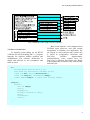
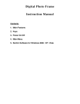
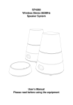
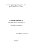
The digital fly-by-wire system is triple
modular redundant. The three computers are
identical in hardware and software. Each
computer samples its inputs, communicates with
other computers via cross channel data link
(CCDL), votes by majority, calculates the
control law and outputs its control value. Fig. 1
shows the block diagram of system architecture.
The system’s input sources are stick and
pedal position sensors, angular rate gyros,
accelerometers, buttons for mode selections, etc.
Outputs are sent to control surface actuators,
indicators and warning lamps, etc.
Control law
DA
Servos
AD
Vote
CCDL
Vote
Control law
DA
Servos
AD
Vote
Control law
DA
Servos
Actuators
Actuators
Actuators
Fig. 1. Block diagram of system architecture
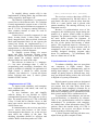
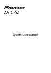
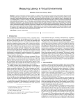
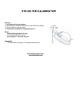
Each computer is constructed by PC-104
modules, as shown in Fig. 2. The computer is a
6-layered stack, approximately 10×10×10cm3.
The system’s kernel is an Athena PC-104
mainboard, which is a high-performance rugged
embedded computer with data acquisition.
1
Jun An Wang and Zhen Shui Li
PC-104 bus
Fig. 2. Modules of the flight control computer
3 Software architecture
To simplify system debug, we use RTOS
VxWorks for task scheduling and C++ program
language for software module partition and
encapsulation. The software architecture is
simple and efficient, as few semaphores and
tasks are used.
Basic work sequence: each computer boots
VxWorks upon power-on, and calls routine
usrAppInit() to initialize user application. For
our system, to start real-time task, routine on()
is called in usrAppInit(). Real-time task
JobCycle()
includes
inputs/outputs,
communications, votes, control laws, etc.
JobCycle() is called on fixed frame-rate. Below
is the pseudocode of function on() and real-time
task JobCycle:
on(){
init DAQ driver,setup AD、DA、DIO, etc;
setup RS485 bus, MIL-1553B bus and ARINC 429 bus;
create task BIT() and task Miscellaneous();
create task JobCycle() and semaphore semSync;
connect semGive(semSync) to system clock interrupt handler;
}
JobCycle(){
while(1){
wait for semSync;
Input();
TickAdjust();
Receive(1); Receive(2); Send();
Vote();
ControlLaws();
Output();
}
}
2
Development of Flight Control System Using Embedded Computer PC-104
To simplify debug, routine off() is also
implemented. In debug mode, the real-time task
can be stopped by shell input “off”.
The function Controllaws() is composed of
several laws with different rates. We calculate
Control augmentation system at rate of 100 Hz,
auto-pilot laws and miscellaneous arguments at
rate of 33.3 Hz. To improve running efficiency,
inner counters instead of tasks are used to
schedule these laws.
Control laws is usually composed of sum
block, 0-order block, 1-order block, 2-order
block, integral block, fade out block, dead-zone
block and saturation block. In our system, the
control law blocks are implemented by C++
class. Tustin transformation has characteristic of
superposition, so the software can deal control
laws in sequence of block diagrams.
To simplify system debug, for sensor
inputs and other arguments, floating points
instead of integers are used as data type; for
sensor inputs, the voltages instead of real
physical values are used as the value.
The software is written in C++ language.
C++ has more advantages than C, such as
encapsulating and overriding. Sometimes, this
leads to problem of reliability. In application of
flight control, it should be taken account
seriously. Our solution is: 1) create all objects
before real-time task runs; 2) check system
health in IF-BIT routine.
4 Implementation of CCDL
To improve task reliability, each computer
must communicate with others, and votes by
each candidate value.
To save hardware cost and simplify
software debug, we use RS-485 as CCDL
communication protocol. The baud rate is 921.6
kbps. The transfer capacity of CCDL: in RS-485,
it uses 11 baud bits to transfer a byte, so 800
more bytes can be sent in a frame, supposing a
100 Hz frame-rate.
In communication, the receiver may fail to
receive correct data because of line break,
electromagnetic interference, etc, so the receiver
must check the validity of the data. The
checking algorithm should be efficient and
reliable. Below is the data packet of CCDL:
[Head] {Fixed-length data} [Checksum]
The receiver receives data into a FIFO in
real-time (implemented by RS-485 driver). In
each frame, the data is moved safely from the
FIFO to a static buffer, and is parsed with
pattern matching. The running efficiency is an
important concern.
Because of synchronization error of the
computers, this checking may begin during the
transfer of a packet, which results in packet
fragment. The solution is simple: In each frame,
the static buffer remains the fragment. In
subsequent frame, the fragment will merge with
the rest of the packet and become a whole
packet. This approach improves efficiency by
eliminating the use of system resource such as
semaphores and tasks. Test shows that the
carefully designed checking program takes
about 2% (minimum) - 7% (maximum) CPU
time at a frame rate of 100 Hz.
5 Synchronization via software
To enhance reliability, there are more than
one computers in flight control. These
computers should work simultaneously, such as
analog input sample, vote and output. If they
sample an analog input in different time, they
may get different analog values, this will result
in degrade of system performance.
Digital control system works on designated
frame rate. With careful design of software, we
can assume that, the time delay from frame
beginning to sensor sampling is constant. So, as
long as each computer’s frame be synchronized,
their sensor sampling will be synchronized, and,
their control output will be synchronized, too.
To synchronize each computer, one can use
a special hardware, or alternately, by software.
There is no synchronization circuit on Athena
motherboard. To synchronize each computer,
we embed timer count information into CCDL
packets. Since the transfer delay of CCDL is
determinate, the receiver can adjust its timer
count according to following rules:
1) If this computer lead (lag) all other ones,
adjust down (up) this computer a little;
3
Jun An Wang and Zhen Shui Li
2) If this computer leads one, but lags the
other one, don’t adjust this computer.
Theoretically,
3
computers
will
synchronize to each other in several frames. In
fact, the computers can’t synchronize absolutely,
the main reasons as below:
To examine the time difference, each
computer saves the count value of its hardware
timer, this is done in a CCDL receiving routine,
which is usually an interrupt service routine
(ISR). The time to response to an interrupt is not
constant, in VxWorks, it varies from 3~20 μs.
After CPU responses the interrupt, the hardware
timer has changed, so the interrupt response
time is a main cause of synchronization error.
By reducing the unnecessary interrupt source
and optimizing the interrupt priority,
synchronization error can be minimized.
For example, computer C lags computer A
and B 5% and 7% of frame time respectively, so
computer C should adjust up 5%, and computer
B should adjust down 2%. To suppress
interference, time base can’t change too much in
each frame. In our system, time base can change
±1% of frame time in each frame. There are still
some special points to stress:
1) To simplify the adjusting algorithm,
timer adjusting should not be done while
overflow. So, timer adjusting is done at the
beginning of a frame, just after AD sampling.
2) The count value of timer, but not the
constant, is adjusted.
Tests show that the mean effective
synchronization error is less than 50 μs.
adjusted interactively. For RTW, S-functions
should be discretized dynamically. But the
RTW hasn’t implemented this function. We
hope this problem be resolved in a newer
version.
2) Simulink can build a simulation model
efficiently, but not a simulation system. Here
are too examples:
Desired: A block which does different
dealings as input changes, and then outputs. Of
course Simulink and RTW can do this, but not
in an efficient and concise manner.
Desired: A sub-system which can be used
as a component with arguments to be assigned
dynamically. To our experience, Simulink
doesn’t possess this “high-level” function.
7 Safety of startup transient
Computers require booting time. While
booting, there’s no control of its output. We
have done some tests on:
1) The maximum booting time. We run
VxWorks on Flash ROMs, the maximum
booting time is less than 2 seconds.
2) Safe state value. All output ports set to
safe state values upon booting.
If a port is closed (i.e. high impedance)
while booting, safe state can be done by adding
a resistor that pulls up or down; if a port is fixed
to low (or high) state while booting, safe state
can be done by buffering or NOT-buffering the
port.
8 Tests and Results
6 Problems of model-based code generators
Model-based code generators have shown
their advantages over manual software
development. For high reliability application,
model-based code generators, like SCADE and
Simulink RTW, are best candidate. We tried
Simulink RTW (in MATLAB 6.5) in our system.
The tool shows its effectiveness and reliability,
but also some limitations, as following:
1) To maximize the performance and
simplify the development of a real-time digital
process control system, single-rate difference
algorithm is often the best choice. In
development stage, we expect the rate be
The system has been tested with an ironbird of a fighter plane. The test includes:
1) Performance and reliability test of
computer system;
2) Test of the control law function: fullauthority fly-by-wire stability augmentation,
stall protection, autopilot, flight director, and
ground proximity warning functions.
As the plane uses a traditional control
augmentation system (till now), test data of the
two systems are compared. Basically, the results
are satisfying. The major problem is actuator
tremble.
4
Development of Flight Control System Using Embedded Computer PC-104
The actuators tremble in testing, the
tremble amplitude sometimes reaches 5%.
Several reasons can lead to actuator’s
tremble, such as electrical interference,
digitalization error, channel difference, etc.
Commercial AD cards usually have high
input impedance. In flight control testing, signal
lines may be longer than several meters. If
sensors are connected to AD cards directly, EMI
problems will be severe, so signal conditioner is
necessary. In our system, impedance matching
circuits and signal buffers are added.
In our system, CCDL is implemented in a
much direct way, so that channel difference may
contribute much to actuator tremble. To
minimize trembling, we add an inertia block
(time constant is 0.02s) before output. Of course,
this diminishes system response performance
slightly, but also diminishes tremble amplitude.
[5] C. E. Hall, Jr. A Real-Time Linux system for
autonomous navigation and flight attitude control of
an uninhabited aerial vehicle. Digital Avionics
Systems Conference, 2001.
[6] XiaoLin Zhang. An Application of Embedded
Computer PC-104 in Flight Control System.
Electronics and Computer, No. 4, pp 26-28, 2003
[7] C. B. Feldstein and J. C. Muzio. Development of a
Fault Tolerant Flight Control System. 2004 IEEE
[8] Tornado user manual, VxWorks Programmer's Guide,
WindRiver co., 2002
Copyright Statement
The authors confirm that they, and/or their company or
institution, hold copyright on all of the original material
included in their paper. They also confirm they have
obtained permission, from the copyright holder of any
third party material included in their paper, to publish it as
part of their paper. The authors grant full permission for
the publication and distribution of their paper as part of
the ICAS2008 proceedings or as individual off-prints
from the proceedings.
9 Conclusions
This paper described the development of a
digital fly-by-wire system. Test results demonstrate that:
1) COTS embedded computers and RTOS
can be used in avionics: They are easy to use,
low cost, flexible and reliable;
2) Architecture of flight control software
can be simple and efficient;
3) Synchronization can be fulfilled by
software.
References
[1] Y. C. Yeh. Design Considerations in Boeing 777 FlyBy-Wire Computers. Proc Conference HighAssurance Systems Engineering Symposium, pp 6472, 13-14 Nov 1998
[2] Henrik B. Christophersen, et al. Small Adaptive
Flight Control Systems for UAVs using FPGA/DSP
Technology. AIAA
[3] Patricia C. Glaab, Michael M. Madden. A Generic
Object-Oriented Implementation for Flight Control
Systems.
AIAA
Modeling
and
Simulation
Technologies Conference and Exhibit, Portland, OR,
Aug. 9-11, 1999, Collection of Technical
papers(A99-36794 09-54) AIAA-1999-4339
[4] Mauro Marinoni, et al. An Embedded Real-Time
System for Autonomous Flight Control. Proc
ANIPLA International Congress on Methodologies
for Emerging Technologies in Automation, 2006
5