1
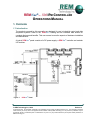
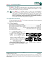
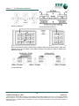
REMVue®
Reciprocating Equipment Manager
Operations Manual
AIR / FUEL RATIO AND GOVERNOR CONTROL
REMVue ®– 500 IPM CONTROLLER
OPERATIONS MANUAL
Version 1a
February 13, 2004
INST ALL AT ION AND HAZ ARDOUS ARE A WAR NINGS
These products should not be used to replace proper safety interlocking. No software-based
device (or any other solid-state device) should ever be designed to be responsible for the
maintenance of consequential equipment or personnel safety. In particular, REM Technology Inc.
disclaims any responsibility for damages, either direct or consequential, that result from the use
of this equipment in any application.
All power, input and output (I/O) wiring must be in accordance with Class I, Division 2 wiring
methods and in accordance with the authority having jurisdiction.
EXPLOSION HAZARD —
SUBSTITUTIO N OF COM PONENTS
M AY IM PAIR SUITABILITY FOR
CLASS 1, DIV ISION 2.
EXPLOSION HAZARD —
W HEN I N HAZARDO US LOCATIONS,
DISCONNECT POW ER B EFO RE
R EPLACING O R W IRI NG MO DULES.
EXPLOSION HAZARD —
DO NOT DISCO NNECT EQ UIPM ENT
UNL ESS POW ER HAS BEEN
SWITCHED O FF O R THE A REA IS
KNOWN TO BE NO NHAZARDO US.
All information in this document applies to REM Vue®– 500 IPm controller and I/O,
except where otherwise noted. Refer to the REM Vue®– 500 I/O Tool Kit software
on-line help system for detailed product specifications and configuration settings.
REMVue® is a registered trademark owned by REM Technology Inc.
© REM Technology Inc., 2004
All rights reserved. All information contained in this publication is the property of REM Technology Inc. The information contained
herein is strictly for use by owners of equipment and/or software made by REM Technology Inc. No part of this publication may be
reproduced, stored in a retrieval system or transmitted in any form or by any means without the prior express written permission of
REM Technology Inc.
REMV u e®– 500 IPM CO NTROLLER
OPERAT ION S MAN UAL
TA BL E OF C O NTE NT S
TABLE OF CONTENTS...................................................................................................................... i
1. Overview....................................................................................................................................1-1
1.1 Introduction ........................................................................................................................... 1-1
1.2 Getting Started with REMVue® Hardware .............................................................................. 1-2
2. Assembly and Installation ........................................................................................................2-4
2.1 REMVue® Panel Assembly .................................................................................................... 2-4
3. Power and ST-Bus Wiring.........................................................................................................3-6
3.1 Power Requirements............................................................................................................. 3-6
3.2 Current Requirements ........................................................................................................... 3-6
3.3 DC Power Wiring................................................................................................................... 3-6
3.4 Redundant Power Inputs ....................................................................................................... 3-7
3.5 ST-Bus Wiring Guidelines...................................................................................................... 3-7
3.5.1 ST-Bus Capability ........................................................................................................... 3-7
4. Communications.......................................................................................................................4-9
4.1 Communication Ports ............................................................................................................ 4-9
4.1.1 RS232 Ports A and B...................................................................................................... 4-9
4.1.2 RS485 Port C.................................................................................................................. 4-9
4.1.3 RS232 Port D................................................................................................................ 4-10
4.1.4 Ethernet Port 1 (Primary) .............................................................................................. 4-11
5. Technical Specifications.........................................................................................................5-12
6. Maintenance Information ........................................................................................................6-16
6.1 Local Diagnostics ................................................................................................................ 6-16
6.2 Status LED.......................................................................................................................... 6-16
6.3 Controller or RTU Memory................................................................................................... 6-16
6.4 Product Support .................................................................................................................. 6-17
–i–
© REM Technology Inc., 2004
Version 1a
All rights reserved. All information contained in this publication is the property of REM Technology Inc. The information contained
herein is strictly for use by owners of equipment and/or software made by REM Technology Inc. No part of this publication may be
reproduced, stored in a retrieval system or transmitted in any form or by any means without the prior express written permission of
REM Technology Inc.
REM V ue ®– 500 IPM CO NT ROL L ER
OPERAT ION S MAN UAL
1. O V ER V IEW
1.1 Introduction
The products covered by this manually are designed for use in industrial control and data
acquisition systems. Refer to the REMVue ® Catalog and the individual data sheets for
complete features and benefits. This user manual covers the aspects of hardware installation
and maintenance.
A typical REMVue ® panel consists of a DC power supply; a REMVue ® controller and modular
I/O modules.
Figure 1
®
REMVue Panel
1-1
© REM Technology Inc., 2004
Version 1a
All rights reserved. All information contained in this publication is the property of REM Technology Inc. The information contained
herein is strictly for use by owners of equipment and/or software made by REM Technology Inc. No part of this publication may be
reproduced, stored in a retrieval system or transmitted in any form or by any means without the prior express written permission of
REM Technology Inc.
REMVue
– 500
®
IPM OPERATIO NS MANUAL
1.2 Getting Started with REMVue ® Hardware
Following these steps will make installation and start-up easier.
1. Mount the Hardware
If you purchased a complete panel system, the complete enclosure is ready for
installation. If you purchased individual components, refer to the following sections of
this or the appropriate user manuals for information on installing them into an
enclosure.
2. Install ST-BUS or Communication Wiring to I/O Modules
Make ST-BUS wiring connections to any REMVue ® I/O module. Refer to a following
section for ST-BUS wiring guidelines.
3. Connect Power and I/O Wiring to the Modules
Connect power to the REMVue ® or user-supplied DC power supply. Make DC power
connections from the power supply to the REMVue ® components. Make field wiring
connections to the REMVue ® I/O modules and any peripheral equipment. Refer to the
appropriate user manuals for I/O connection details.
4. Install Communication Cabling
The units covered by this manual come with communication accessories. Snap the
pre-wired RJ45 to DB9 adapter to the RJ45 patch cord (not supplied). Connect this
cable between one of the serial RS232 ports (RJ45 connector) on your controller and
a serial RS232 port (DB9 connector) on your PC.
Fabricate and install RS232 and RS485 cables as needed to connect to other
devices. If you are using Ethernet units, install the correct cabling and peripherals.
Refer to the documentation for your Ethernet communication devices for details.
5. Apply Power
Power up the REMVue ® components and related peripherals. Observe the status LED
on each unit. Typically, a solid ON indicates proper operation. A blinking LED may
indicate that the unit needs to be configured. Refer to the appropriate REMVue ® user
manual for details.
6. Configure Using the REMVue ® I/O Tool Kit
Refer to the steps on the next page to create a hardware configuration for each
REMVue ® station. Refer to the on-line help in the I/O Tool Kit for details.
7. Test the Hardware
Use the Test I/O window in the I/O Tool Kit program to verify proper I/O operation of
all REMVue ® stations. Refer to the I/O Tool Kit on-line help system.
– 1-2 –
© REM Technology Inc., 2004
Version 1a
All rights reserved. All information contained in this publication is the property of REM Technology Inc. The information contained
herein is strictly for use by owners of equipment and/or software made by REM Technology Inc. No part of this publication may be
reproduced, stored in a retrieval system or transmitted in any form or by any means without the prior express written permission of
REM Technology Inc.
REMVue
– 500
®
IPM OPERATIO NS MANUAL
8. Configure Your PC Software to Communicate with the REMVue ® Station(s)
Refer to the documentation for your software.
9. If You Have Difficulty
If you experience startup trouble, refer to a following page in this document for some
trouble-shooting tips or phone RTI Technical Support for help.
– 1-3 –
© REM Technology Inc., 2004
Version 1a
All rights reserved. All information contained in this publication is the property of REM Technology Inc. The information contained
herein is strictly for use by owners of equipment and/or software made by REM Technology Inc. No part of this publication may be
reproduced, stored in a retrieval system or transmitted in any form or by any means without the prior express written permission of
REM Technology Inc.
REMVue
– 500
®
IPM OPERATIO NS MANUAL
2. A SS E MB LY AN D IN S TALLATIO N
2.1 REMVue ® Panel Assembly
Most REMVue ® components snap onto DIN rail strips fastened to a sub panel. Figure 2
shows a sample panel with DIN rail strips and wire duct attached. Recommended DIN rail
spacing is 8 inches. This spacing allows room for wire duct to be installed without
obstructing field wiring installation.
The REMVue ® components are typically installed against one another, but space may be
left between modules to accommodate other DIN rail mounted components such as
terminal blocks and fuse holders. End clamps are recommended to restrict side-to-side
movement. Figure 3 shows the physical dimensions of the units covered by this manual.
REMVue ® components can be installed in any orientation and order on your panel.
8.0"
(20.3 cm)
Wire Duct
Wire Duct
Wire Duct
Wire Duct
8.0"
(20.3 cm)
33.0"
(83.8 cm)
8.0"
(20.3 cm)
Wire Duct
6.5"
(16.5 cm)
Wire Duct
27.0" (68.6 cm)
Figure 2
Sample Layout for a 36" × 30" Enclosure
– 2-4 –
© REM Technology Inc., 2004
Version 1a
All rights reserved. All information contained in this publication is the property of REM Technology Inc. The information contained
herein is strictly for use by owners of equipment and/or software made by REM Technology Inc. No part of this publication may be
reproduced, stored in a retrieval system or transmitted in any form or by any means without the prior express written permission of
REM Technology Inc.
REMVue
– 500
®
IPM OPERATIO NS MANUAL
Figure 3
®
REMVue Controller Dimensions
– 2-5 –
© REM Technology Inc., 2004
Version 1a
All rights reserved. All information contained in this publication is the property of REM Technology Inc. The information contained
herein is strictly for use by owners of equipment and/or software made by REM Technology Inc. No part of this publication may be
reproduced, stored in a retrieval system or transmitted in any form or by any means without the prior express written permission of
REM Technology Inc.
REMVue
– 500
®
IPM OPERATIO NS MANUAL
3. POW E R AN D ST- B U S W IR IN G
3.1 Power Requirements
REMVue ® IPm controllers accept 24 VDC power from a user DC power source of 10 to
30 VDC.
3.2 Current Requirements
To calculate the current requirements, add the wattage required for the REMVue ®
controller and modules in use. Then divide the total wattage by the DC power source
voltage. Then add any current needed for user instrumentation loops.
3.3 DC Power Wiring
All REMVue ® units and user instrumentation loops may be powered from a single DC
source. Refer to Figure 4 for typical DC power connections. The user DC power source
must be between 10 to 30 volts.
Figure 4
®
REMVue Power Connections
– 3-6 –
© REM Technology Inc., 2004
Version 1a
All rights reserved. All information contained in this publication is the property of REM Technology Inc. The information contained
herein is strictly for use by owners of equipment and/or software made by REM Technology Inc. No part of this publication may be
reproduced, stored in a retrieval system or transmitted in any form or by any means without the prior express written permission of
REM Technology Inc.
REMVue
– 500
®
IPM OPERATIO NS MANUAL
3.4 Redundant Power Inputs
The REMVue ® controller has a redundant power + input terminal. (There is one common
power — terminal.) This allows you to connect two separate power supplies. If one fails
then the other will take over powering your hardware.
In the REM Vue ®– 500 controller, the ST C (+) and ST D (-) of the ST-BUS are
internally connected to only the primary power input (terminals 2 and 4). Therefore,
when running on only auxiliary power (terminals 3 and 4) then there will be no power
on terminals 16 and 17 (ST C and ST D). If redundant power is desired for the STBUS it is recommended that the auxiliary power + be connected to terminal 16
through an external diode. The diode should be appropriately sized (current rating)
for the number of I/O modules being powered (see Figure 4).
3.5 ST-Bus Wiring Guidelines
ST-Bus wiring connects the REMVue ® I/O modules to the controller. Follow the upcoming
guidelines for reliable performance.
3.5.1 ST-Bus Capability
Max. modules controlled by one controller .....................................................................128
Max. modules connected directly to controller................................................. 20 (any mix)
Max. modules connected to expander output .................................................. 20 (any mix)
Required cable type.............................Any with 2 individually shielded pairs, 22AWG min.
Recommended cables.........................................Alpha 2466C, Belden 8723, Carol C1352
Max. cabling off each controller.......................................................................... 50 ft. (16M)
RTU or
Controller
I/O
Connect up to 20 I/O modules or expanders directly
to the controller with a maximum total cabling of 50
feet. Likewise, connect up to 20 I/O modules to
each expander.
I/O
Expander
Expander
Expander
I/O
I/O
All expanders must be connected directly to the
controller. (Expanders cannot be cascaded in
series.)
– 3-7 –
© REM Technology Inc., 2004
Version 1a
All rights reserved. All information contained in this publication is the property of REM Technology Inc. The information contained
herein is strictly for use by owners of equipment and/or software made by REM Technology Inc. No part of this publication may be
reproduced, stored in a retrieval system or transmitted in any form or by any means without the prior express written permission of
REM Technology Inc.
REMVue
– 500
®
IPM OPERATIO NS MANUAL
ST-Bus connections may form star configurations
without any restrictions.
Route ST-Bus wiring away from power wiring and
sources of electrical interference.
Expanders may be used in cabinets with more than 20 I/O modules as long as the total length of wire stays
within the 50-foot limit. Extending ST-Bus wiring to additional cabinets is not recommended. Instead, use a
gateway, RTU or I/O concentrator in each additional cabinet and run Ethernet, RS232 or RS485 wiring
between the cabinets.
Use the supplied ST-Bus jumpers between adjacent REMVue ® components. Otherwise, use the
recommended cable.
– 3-8 –
© REM Technology Inc., 2004
Version 1a
All rights reserved. All information contained in this publication is the property of REM Technology Inc. The information contained
herein is strictly for use by owners of equipment and/or software made by REM Technology Inc. No part of this publication may be
reproduced, stored in a retrieval system or transmitted in any form or by any means without the prior express written permission of
REM Technology Inc.
REMVue
– 500
®
IPM OPERATIO NS MANUAL
4. CO M MU N IC ATIO N S
4.1 Communication Ports
The REMVue ® controllers covered by this manual have various combinations of Ethernet
and serial ports. See the chart below.
Product
REMVue ® –
500
RS232
Port A
Ð
RS232
Port B
Ð
RS485
Port C
Ð
RS232 Ethe rne t Ethe rne t Built-In
Port D
Port1
Port 2
Sw itch
Ð
Ð
—
—
4.1.1 RS232 Ports A and B
These ports are identical in connection and functionality. A RJ45 female connector is
provided for each. The pin-outs follow the EIA/TIA-561standard (see Figure 5). A prewired DB9F to RJ45F adapter is included with these units. Use this adapter along with a
RJ45 male to RJ45 male straight-thru wired patch cable (not included) to make a
connection between a com port on your PC (DB9 male) and either Port A or B (RJ45
female). Refer to the REMVue ® Catalog for more information on connecting to other
equipment.
RJ45 Pin Locations
(For RS232 or Ethernet)
4.1.2 RS485 Port C
This port is found on all units. It provides a RS485 (two-wire, half duplex only) connection
to other equipment. Four terminals (for signal gnd, 485+, 485-, and termination) are
provided. Generally, you connect + to + and - to - between units. However, since there is
no standard for RS485 terminal designations you may need to connect + to - and - to + in
some cases. No damage will result if you connect incorrectly. It is highly recommended
that you tie the signal ground to an appropriate ground (if available) between all RS485
units. Make sure to use a good quality communication cable with three conductors
(twisted is preferred) plus a shield. To prevent ground loops, the shield should be
connected to chassis ground on only one end of any cable run.
If you have existing wiring that has only two conductors and a shield, you can use the
shield to connect the signal grounds between stations. This is not optimal (especially
for long cable runs) but should work in most situations.
– 4-9 –
© REM Technology Inc., 2004
Version 1a
All rights reserved. All information contained in this publication is the property of REM Technology Inc. The information contained
herein is strictly for use by owners of equipment and/or software made by REM Technology Inc. No part of this publication may be
reproduced, stored in a retrieval system or transmitted in any form or by any means without the prior express written permission of
REM Technology Inc.
REMVue
– 500
®
IPM OPERATIO NS MANUAL
RS485 Termination
All these units have RS485 termination components (150 ohm resistor and a 0.1 µF
capacitor connected in series) already inside. To terminate your RS485 network just tie
the "T" terminal to the RS485 — terminal. Make sure to use the same type and size
conductor as used already used for your RS485 — connection. It is recommended that
both end stations of your RS485 network be terminated. Avoid terminating more than two
stations. For third party devices, please refer to their user manual for termination
instructions.
Bias Resistors
On a RS485 two-wire network, a pair of bias resistors (1K ohm typically) acting upon the
transmit/receive wires may be required. If bias resistors are not present, the receive
inputs on some RS485 devices may react to noise on the floating wires. The bias
resistors will force the transmit/receive wires to a known (non-floating) state when none of
the RS485 devices are transmitting data. Some RS485 devices have bias resistors builtin, and are enabled through DIP-switch or jumper settings. Make sure there is only one
pair of bias resistors acting upon the network.
If your RS485 network is made up exclusively of REM Vue ® devices, these bias
resistors are not necessary.
4.1.3 RS232 Port D
Five screw terminals (for TD, RD, RTS, CTS, and GND) are provided to make your
connections.
The 5th terminal is signal ground and is shared by the adjacent RS485 Port C. Refer
to Figure 5 for the exact connections.
– 4-10 –
© REM Technology Inc., 2004
Version 1a
All rights reserved. All information contained in this publication is the property of REM Technology Inc. The information contained
herein is strictly for use by owners of equipment and/or software made by REM Technology Inc. No part of this publication may be
reproduced, stored in a retrieval system or transmitted in any form or by any means without the prior express written permission of
REM Technology Inc.
REMVue
– 500
®
IPM OPERATIO NS MANUAL
Figure 5
REMVue ® Communication Connections
4.1.4 Ethernet Port 1 (Primary)
It is a 10/100BaseTx auto-detecting and auto-crossover Ethernet port. This means it will
auto-detect the speed, and work with either a straight-thru or cross-wired Ethernet cable.
A standard shielded RJ45 connector is provided. See the figures below for the pin-outs.
This port has a fixed unique MAC address. The IP address can be set with the REMVue ®
I/O Tool Kit software. Refer to the on-line help for details.
– 4-11 –
© REM Technology Inc., 2004
Version 1a
All rights reserved. All information contained in this publication is the property of REM Technology Inc. The information contained
herein is strictly for use by owners of equipment and/or software made by REM Technology Inc. No part of this publication may be
reproduced, stored in a retrieval system or transmitted in any form or by any means without the prior express written permission of
REM Technology Inc.
REMVue
– 500
®
IPM OPERATIO NS MANUAL
5. TE C H N IC AL S P E C IFIC ATIO NS
Below are the technical specifications for the REMVue ® IPm Controller.
Ge ne ra l
Compatibility with legacy VersaTRAK RTU and
SixTRAK Programmable I/O Gateway
Operating system
Unique station addresses (unit Ids)
Dynamic memory (RAM)
(for program execution, dynamic variables,
dynamic file system, etc.)
Program memory (Flash)
(for Linux OS, program storage, and file system)
Datalogging memory (RAM)
(for datalogging and retained variables )
Battery -backup time / life
Real-time clock resolution
Real-time clock accuracy
I/O expansion
Maximum local I/O (via ST-Bus port)
Indu stria l Pow e rPC (32 bit da ta bus)
Fully (except there is no on-board I/O)
Embedded LINUX
16,000+ (REMVue®) or 247 (Modbus)
32bit, 0 wait states
16 Megabytes
8 Megabytes
Battery -backed – Rechargeable Lithium
512K bytes
1 year / 10+ years
10 mS
+/-15 seconds per month
SixTRAK, EtherTRAK, RemoteTRAK
1,024 (128 SixTRAK modules) (expander required
after every 20 modules )
Maximum distributed I/O (application dependent) 50,000+
Datalogging support
Yes – SIXNET Sixlog
Datalogging modes
Trending, alarm logging, sequence of events, event
initiated, client transfers, and others
LINUX capabilities
Practically unlimited
Programming
High level C and others
Number of applications allowed
As many as there is memory for
Available FREE source code
Practically unlimited
IEC 61131 PLCopen programming
Yes – SIXNET ISaGRAF
Languages supported
Ladder logic, function chart, function block,
instruction list, structured text, and flow chart
Number of programs allowed to be run in IPm at 2
same time
Cycle time
10 mS minimum (user settable)
Communication capabilities
Master, slave, peer to peer, report on exception,
store and forward and more
Communication media supported
Ethernet, telemetry, telephone (dialup and leased
line), radio (dumb and smart ), other wireless, fiber
optic, short haul and more
– 5-12 –
© REM Technology Inc., 2004
Version 1a
All rights reserved. All information contained in this publication is the property of REM Technology Inc. The information contained
herein is strictly for use by owners of equipment and/or software made by REM Technology Inc. No part of this publication may be
reproduced, stored in a retrieval system or transmitted in any form or by any means without the prior express written permission of
REM Technology Inc.
REMVue
– 500
®
IPM OPERATIO NS MANUAL
Re dunda ncy
Redundant Ethernet links (ST-IPm only)
Va rious le ve ls suppo rte d
Yes – 2 unique MAC & IP addresses allow for 2
unique network connections
Yes – multiple modules can interface to the same
I/O; an internal discrete bit reports on-line status of
each module
Yes – automatic controller switch-over is supported
(user application programming required)
Yes – automatic switch-over on failure
Yes – especially with EtherTRAK modules
Redundant I/O modules
Redundant controllers
Redundant power
Backup RS485 communications
W a tchdog s a nd Monitor s
CPU watchdog
For run- tim e dia gnostic s
CPU automatically resets if error is detected; status
LED flashes error code
Settable timeout and output action (force off or
freeze)
Settable timeout & output action (force off or
freeze)
Communicat ions watchdog
Heartbeat watchdog
Ethe rne t Port ( s)
Connection
Isolation
Message response time (typical)
Diagnostic LEDs on each port
Protocols supported
10/10 0Ba se Tx (a uto-de te cting )
RJ45 (auto-crossover)
1,500 Volts RMS 1 minute (60 Hz.)
5 mS
Indicates speed, link and activity
TCP/IP, ARP, UDP, ICMP, DHCP, Modbus/TCP,
SIXNET, and more
VT-IPm & ST-GT = 1 w/ unique MAC & IP address
ST-IPm = 2 w/ unique MAC & IP addresses
1 shielded RJ45 connector
Same as RTI’s 10-7576
Independent networks
Network port 1
Integrated Ethernet switch features
Se rial Ports
RS232 Port A
RS232 Port B
RS485 Port C
300 t o 11 5,200 ba ud
RJ45 (TD, RD, CTS, RTS, CD, DTR, DSR/RI , GND)
RJ45 (TD, RD, CTS, RTS, CD, DTR, DSR/RI , GND)
Screws (GND, 485+, 485-, termination) (two-wire
half-duplex) (GND common with port D)
Up to 32 (full-load) stations
Up to 0.5 miles (1 km)
Screws (TD, RD, RTS, CTS, GND)
SIXNET & Modbus (RTU and ASCII); Many others
available in LINUX
Transmit Data (TD) & Receive Data (RD)
Hardware, software, RTS-party (for radios and
RS485)
RS485 network
RS485 distance
RS232 Port D
Protocols (master & slave)
Diagnostic LEDs on each port
Flow Control
– 5-13 –
© REM Technology Inc., 2004
Version 1a
All rights reserved. All information contained in this publication is the property of REM Technology Inc. The information contained
herein is strictly for use by owners of equipment and/or software made by REM Technology Inc. No part of this publication may be
reproduced, stored in a retrieval system or transmitted in any form or by any means without the prior express written permission of
REM Technology Inc.
REMVue
– 500
®
IPM OPERATIO NS MANUAL
ST-B US (loca l I/O) port
Modules
I/O channels
Scan time
Benchmark 1: 48 discretes & 8 analog
Benchmark 2: 512 discretes
Benchmark 3: 128 analogs
Benchmark 3: 512 discretes & 128 analogs
Cable length
Wiring configurations
Cable type required
Full line of a na log a nd discre te I/O
Up to 128 (including expanders)
Up to 1,024
5 mS minimum (varies depending on quantity and
type of I/O modules)
10 mS
30 mS
40 mS
80 mS
50 ft. (16 m.)
Daisy-chain or star
2 individually shielded pairs, 22 AWG min.
I/O Tool Kit W indow s Softw a re
Operating systems
Minimum system requirements
Le ve l 1 provide d free with a ll sy ste m s
95, 98, ME, NT, 2000, and XP
Pentium or equivalent, 32 Mb RAM, 100 Mb hard
disk space
Configuration, calibration, diagnostics, and limited
exporting of I/O definitions.
Full importing and exporting of I/O definitions, peer
to peer I/O transfers, and the IOmap shared
database.
Datalogging capability and quick load feature
“Load All”.
LINUX functionality and support.
Web Server functionality and support.
Option 1 (Basic)
Option 2 (SCS)
Option 3 (Datalogging)
Option 4 (LINUX)
Option 5 (Web Server)
Envir onm e nta l
Input voltage
Input power (@ 24 VDC unless otherwise
noted) (±10%)
DIN ra il or fla t pa ne l m ount
10-30 VDC (integrated switching supply),
(External AC/DC or DC/DC supplies optional)
2.4 W (110 mA) – typical (no communications)
2.7 W (112 mA) – typical (serial communications only)
3.1 W (128 mA) – typical (all ports communicating)
(rated current at max. voltage 30 VDC is 125 mA)
The
power
consumption
variations mostly depend on the
number of Ethernet and/or serial
connections.
Redundant power inputs
Temperature
Humidity
Yes with automatic switch over, diode protection,
and internal voltage monitoring
-40 to 70 °C (-40 to 85 °C storage)
5% to 95% RH (non-condensing)
(optional conformal coating)
UL 94V-0 materials
UL 508, CSA C22.2/14; EN61010-1 (IEC1010); CE
FCC part 15, ICES-003, Class A; EN55022;
EN61326-1; CE
EN61326-1 (EN61000-4-2,3,4,6); CE
IEEE-472 (ANSI C37.90); EN61000-4-2, 4
Flammability
Electrical Safety
EMI emissions
EMC immunity
Surge withstand
– 5-14 –
© REM Technology Inc., 2004
Version 1a
All rights reserved. All information contained in this publication is the property of REM Technology Inc. The information contained
herein is strictly for use by owners of equipment and/or software made by REM Technology Inc. No part of this publication may be
reproduced, stored in a retrieval system or transmitted in any form or by any means without the prior express written permission of
REM Technology Inc.
REMVue
– 500
®
IPM OPERATIO NS MANUAL
Vibration
Hazardous locations
(Class 1, Div 2, Groups A, B, C, D)
Marine & Offshore
Packaging
Mounting
Size
IEC68-2-6
UL 1604, CSA C22.2/213,
Cenelec EN50021 Zone 2
DNV (Det Norske Veritas)
Alum. cover (iridite finish) on Lexan base
DIN rail (EN50022) or direct to panel
4.75”L × 3.25”W × 2.65”H
(121mm × 83mm × 67mm)
0.730 Lbs.
Weight
– 5-15 –
© REM Technology Inc., 2004
Version 1a
All rights reserved. All information contained in this publication is the property of REM Technology Inc. The information contained
herein is strictly for use by owners of equipment and/or software made by REM Technology Inc. No part of this publication may be
reproduced, stored in a retrieval system or transmitted in any form or by any means without the prior express written permission of
REM Technology Inc.
REMVue
– 500
®
IPM OPERATIO NS MANUAL
6. MAIN TE N AN C E IN FO R MATIO N
6.1 Local Diagnostics
Local diagnostics can be performed through any available port while the controller is
responding to messages from the other port. Diagnostic software, such as the REMVue®
I/O Tool Kit, can be used to display the status of the I/O registers. Refer to the software's
on-line help for details.
6.2 Status LED
The "Status" LED on the controller or RTU indicates its operational status:
ON
The controller or RTU is operating properly.
OFF
There is no power to the controller or service is required. Contact REM Technology Inc.
technical support.
FAST BLINK
This may occur when the controller is being reset, or firmware is to be downloaded from
the I/O Tool Kit software.
SLOW or PERODIC BLINK
This indicates that the internal watchdog has detected a problem. Try clearing the
memory and reloading the project from the I/O Tool Kit.
6.3 Controller or RTU Memory
These REMVue® controllers have non-volatile (battery-free) memory for storing
configuration data from the I/O Tool Kit utility.
They also have battery-backed memory for storage of program variables and logged
data. The battery is a rechargeable lithium cell that is kept fresh by the power circuitry in
the controller. The memory retention period for an unpowered controller or RTU is at least
six months at room temperature. The retention time will be shorter at higher
temperatures. The life expectancy of the lithium battery is approximately 10 years or
more.
– 6-16 –
© REM Technology Inc., 2004
Version 1a
All rights reserved. All information contained in this publication is the property of REM Technology Inc. The information contained
herein is strictly for use by owners of equipment and/or software made by REM Technology Inc. No part of this publication may be
reproduced, stored in a retrieval system or transmitted in any form or by any means without the prior express written permission of
REM Technology Inc.
REMVue
– 500
®
IPM OPERATIO NS MANUAL
6.4 Product Support
To obtain support for REMVue® products, call REM Technology Inc. and ask for
Applications Engineering.
REM T ECHNOLOGY INC .
305 – 27 Street SE
Calgary, AB T2A 7V2
CANADA
PHONE:
FAX:
E-M AIL:
(403) 207-0630
(403) 273-5835
[email protected]
Visit us on the Web at http://www.remtechnology.com
– 6-17 –
© REM Technology Inc., 2004
Version 1a
All rights reserved. All information contained in this publication is the property of REM Technology Inc. The information contained
herein is strictly for use by owners of equipment and/or software made by REM Technology Inc. No part of this publication may be
reproduced, stored in a retrieval system or transmitted in any form or by any means without the prior express written permission of
REM Technology Inc.