1
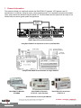
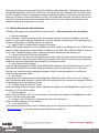
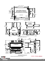
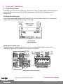
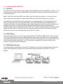
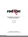
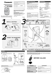
EtherTRAK I/O Modules, I/O Expander, and I/O Concentrator User Manual December 2013 This manual applies to the following products: All EtherTRAK I/O modules (ET-) EtherTRAK I/O Expander (ET-GT-ST-1) – (Now obsolete – replaced by ET-GT-ST-2) EtherTRAK I/O Concentrator (ET-GT-ST-2) www.redlion.net 1 CHANGE HISTORY Version Date Description 12/20/2013 Added translation for Installation and Harzardous Area Warnings. Red Lion Controls Worldwide Headquarters 20 Willow Springs Circle, York, PA, 17406 FLEXIBLE. RELIABLE. POWERFUL. T +1 717 767 6511 www.redlion.net © 2013. Sixnet. All Rights Reserved. 2 TABLE OF CONTENTS 1 2 3 4 5 6 7 8 General Information ............................................................................................................................................7 1.1 General Specification .............................................................................................................................................. 8 1.2 Sixnet Software Tools.............................................................................................................................................. 8 1.3 Getting Started with Sixnet Hardware .................................................................................................................... 9 1.4 Using Sixnet Windows Software ........................................................................................................................... 10 Assembly and Installation.................................................................................................................................. 11 2.1 Panel Assembly ..................................................................................................................................................... 11 Power and ST_BUS Wiring ................................................................................................................................. 13 3.1 Power Requirements ............................................................................................................................................ 13 3.2 Current Requirements .......................................................................................................................................... 14 3.3 ST-Bus Wiring Guidelines ...................................................................................................................................... 14 3.4 Screw Torque ........................................................................................................................................................ 15 Communications ............................................................................................................................................... 16 4.1 Communication Ports ........................................................................................................................................... 16 Configuring EtherTRAK I/O ................................................................................................................................ 20 5.1 Operation .............................................................................................................................................................. 20 5.2 RS232 Wiring ......................................................................................................................................................... 20 5.3 RS232 Mode Selection .......................................................................................................................................... 20 5.4 Sixnet I/O Toolkit................................................................................................................................................... 21 5.5 Modes of Operation .............................................................................................................................................. 21 5.6 EtherTRAK LEDs ..................................................................................................................................................... 22 5.7 I/O Module Status LEDs ........................................................................................................................................ 22 5.8 Expander or Concentrator Status LED................................................................................................................... 23 5.9 Status LED Wink Feature ....................................................................................................................................... 23 5.10 Expander or Concentrator TD/RD LEDs ................................................................................................................ 23 5.11 ACT/LNK LEDs ........................................................................................................................................................ 23 Discrete I/O Modules ........................................................................................................................................ 24 6.1 ET-8DI2-8DO2 Overview ....................................................................................................................................... 24 6.2 Wiring and Jumpers .............................................................................................................................................. 24 6.3 TPO Feature .......................................................................................................................................................... 24 6.4 I/O Registers .......................................................................................................................................................... 25 6.5 ET-16DI2 Overview................................................................................................................................................ 25 6.6 Wiring and Jumpers .............................................................................................................................................. 25 6.7 I/O Registers .......................................................................................................................................................... 26 6.8 ET-8CNT Overview ................................................................................................................................................ 26 6.9 Input Wiring .......................................................................................................................................................... 27 6.10 I/O Registers .......................................................................................................................................................... 27 Discrete Output Modules .................................................................................................................................. 28 7.1 ET-16DO2 Overview .............................................................................................................................................. 28 7.2 Wiring .................................................................................................................................................................... 28 7.3 TPO Feature .......................................................................................................................................................... 28 7.4 I/O Registers .......................................................................................................................................................... 29 Discrete Analog Modules ................................................................................................................................... 30 8.1 ET-8DI2-8AI2 Overview ......................................................................................................................................... 30 8.2 Wiring and Jumpers .............................................................................................................................................. 30 8.3 Current Shunts ...................................................................................................................................................... 30 8.4 I/O Registers .......................................................................................................................................................... 31 Red Lion Controls Worldwide Headquarters 20 Willow Springs Circle, York, PA, 17406 FLEXIBLE. RELIABLE. POWERFUL. T +1 717 767 6511 www.redlion.net © 2013. Sixnet. All Rights Reserved. 3 8.5 ET-4RTD-4DI2 Overview ........................................................................................................................................ 31 8.6 Wiring and Jumpers .............................................................................................................................................. 31 8.7 I/O Registers .......................................................................................................................................................... 32 8.8 ET- MIX24880 Overview........................................................................................................................................ 32 8.9 Discrete Input and Output Wiring......................................................................................................................... 32 8.10 Analog Input Wiring .............................................................................................................................................. 35 9 Analog Input Modules ....................................................................................................................................... 37 9.1 ET-16AI2 Overview ................................................................................................................................................ 37 9.2 Wiring .................................................................................................................................................................... 37 9.3 Current Shunts ...................................................................................................................................................... 37 9.4 ET-8INS Overview .................................................................................................................................................. 38 9.5 ET-8INS Wiring ...................................................................................................................................................... 38 9.6 4-20 mA Input Jumpers ......................................................................................................................................... 38 9.7 Current Shunts ...................................................................................................................................................... 38 9.8 I/O Registers .......................................................................................................................................................... 38 10 Analog I/O Module ....................................................................................................................................... 39 10.1 ET-8AI2-4AO2 Overview........................................................................................................................................ 39 10.2 Wiring .................................................................................................................................................................... 39 10.3 I/O Registers .......................................................................................................................................................... 39 11 Service Information....................................................................................................................................... 40 11.1 Product Support .................................................................................................................................................... 40 Red Lion Controls Worldwide Headquarters 20 Willow Springs Circle, York, PA, 17406 FLEXIBLE. RELIABLE. POWERFUL. T +1 717 767 6511 www.redlion.net © 2013. Sixnet. All Rights Reserved. 4 STATEMENT OF LIMITED WARRANTY Red Lion, manufacturer of SixTRAK, VersaTRAK, RemoteTRAK and EtherTRAK products, warrants to Buyer that products manufactured by Red Lion will be free from defects in material and workmanship. Red Lion’s obligation under this warranty will be limited to repairing or replacing, at Red Lion’s option, the defective parts within 1 year of the date of installation, or within 18 months of the date of shipment from the point of manufacture, whichever is sooner. Products may be returned by Buyer only after permission has been obtained from Red Lion. Buyer will prepay all freight charges to return any products to the repair facility designated by Red Lion. This limited warranty does not cover losses or damages that occur in shipment to or from Buyer or due to improper installation, maintenance, misuse, neglect or any cause other than ordinary commercial or industrial applications, This limited warranty is in lieu of all other warranties whether oral or written, expressed or implied. Red Lion’s liability shall not exceed the price of the individual unit which is the basis of the claim. In no event shall Red Lion be liable for any loss of profits, loss of use of facilities or equipment or other indirect, incidental or consequential damages. Red Lion Controls Worldwide Headquarters 20 Willow Springs Circle, York, PA, 17406 FLEXIBLE. RELIABLE. POWERFUL. T +1 717 767 6511 www.redlion.net © 2013. Sixnet. All Rights Reserved. 5 INSTALLATION AND HAZARDOUS AREA WARNINGS These products should not be used to replace proper safety interlocking. No software-based device (or any other solid-state device) should ever be designed to be responsible for the maintenance of consequential equipment or personnel safety. In particular, Red Lion disclaims any responsibility for damages, either direct or consequential, that result from the use of this equipment in any application. All power, input and output (I/O) wiring must be in accordance with Class I, Division 2 wiring methods and in accordance with the authority having jurisdiction. WARNING – EXPLOSION HAZARD – SUBSTITUTION OF COMPONENTS MAY IMPAIR SUITABILITY FOR CLASS 1, DIVISION 2. WARNING – EXPLOSION HAZARD – WHEN IN HAZARDOUS LOCATIONS, DISCONNECT POWER BEFORE REPLACING OR WIRING MODULES. WARNING – EXPLOSION HAZARD – DO NOT DISCONNECT EQUIPMENT UNLESS POWER HAS BEEN SWITCHED OFF OR THE AREA IS KNOWN TO BE NONHAZARDOUS. These products are operator interface units to be used within control panels. These devices are intended for use in Class I, Division 2, Hazardous Locations, industrial control applications. The enclosure shall be suitable for the location. A minimum IP54 rated enclosure is needed for ATEX unless an equivalent degree of protection is supplied by the location. These products are to be used within control panels in hazardous locations. The enclosure shall be suitable for this location. Hotswapping is not for use in hazardous locations. AVERTISSEMENTS POUR INSTALLATION ET ENDROITS DANGEREUX Ces produits ne doivent pas être utilisés pour remplacer le verrouillage de sécurité approprié. Aucun dispositif basé sur un logiciel (ou tout autre dispositif à l'état solide) devraient jamais être conçus pour être responsable de l'entretien de l'équipement consécutifs ou la sécurité du personnel. En particulier, Red Lion décline toute responsabilité pour les dommages, directs ou indirects, résultant de l'utilisation de cet équipement dans n'importe quelle application. Tout courant, câblage entrée et sortie (I / O) doit être conforme aux méthodes de câblage à la Classe I, Division 2 et conformément à l'autorité compétente. AVERTISSEMENT – RISQUE D’EXPLOSION – LA SUBSTITUTION DE TOUT COMPOSANT PEUT NUIRE À LA CONFORMITÉ DE CLASSE I, DIVISION 2 AVERTISSEMENT – RISQUE D’EXPLOSION – LORSQUE DANS DES ENDROITS DANGEREUX, DÉBRANCHEZ LE CORDON D'ALIMENTATION AVANT DE REMPLACER OU DE BRANCHER LES MODULES. AVERTISSEMENT – RISQUE D’EXPLOSION – NE DÉBRANCHEZ PAS L'ÉQUIPEMENT À MOINS QUE L'ALIMENTATION AIT ÉTÉ COUPÉE OU QUE L’ENVIRONNEMENT EST CONNU POUR ÊTRE NON DANGEREUX. Ces produits sont des unités d'interface opérateur qui doivent être utilisés à l'intérieur des panneaux de commande. Ces appareils sont destinés à une utilisation en Classe I, Division 2, zones dangereuses, applications de contrôle industriel. L'enclos doit être adapté à l’environnement lieu. Un boîtier IP54 minimum est nécessaire pour ATEX à moins qu’un degré équivalent de protection est fourni par l'emplacement. Lorsque dans des endroits dangereux, ces produits doivent être utilisés dans des panneaux de contrôle. Pas de remplacement à chaud des modules dans les zones dangereuses Note: All information in this document applies to EtherTRAK I/O modules, I/O Expander, and I/O Concentrator; except where otherwise noted. Refer to the Sixnet I/O Tool Kit software online help systems for detailed product specifications and configuration settings. Red Lion Controls Worldwide Headquarters 20 Willow Springs Circle, York, PA, 17406 FLEXIBLE. RELIABLE. POWERFUL. T +1 717 767 6511 www.redlion.net © 2013. Sixnet. All Rights Reserved. 6 1 General Information This manual will help you install and maintain the EtherTRAK I/O modules, I/O Expander, and I/O Concentrator. In summary, wiring for power, communications and I/O is connected to each module’s base. Then, setup choices are entered using the Sixnet I/O Tool Kit software and the system will be ready to run. Shown below are some typical system configurations. Ethernet Switch Distribute EtherTRAK I/O modules off of SIXNET Open RTUs and DCS Controllers Using EtherTRAK I/O as Expansion I/O for a VersaTRAK RTU Using an EtherTRAK I/O Concentrator for Larger Stations EtherTRAK I/O Modules ET-####-# EtherTRAK I/O Expander ET-GT-ST-1 (now obsolete) EtherTRAK I/O Concentrator ET-GT-ST-2 Sixnet Products Covered by this Manual Red Lion Controls Worldwide Headquarters 20 Willow Springs Circle, York, PA, 17406 FLEXIBLE. RELIABLE. POWERFUL. T +1 717 767 6511 www.redlion.net © 2013. Sixnet. All Rights Reserved. 7 1.1 General Specification These general specifications apply to all EtherTRAK I/O modules. More detailed product specifications may be found in the online help system of the Sixnet I/O Toolkit configuration utility. Required Power RS485 Expansion Ethernet port Ethernet Isolation Operating Temp. Humidity Protocols 10-30 VDC (I/O modules); 18-30 VDC (I/O Expander/Concentrator with SixTRAK modules); 10-30 VDC (I/O Expander/Concentrator without any SixTRAK modules connected) Connect up to 32 RemoteTRAK modules or Modbus devices 10BaseT (10 Mbps); RJ45 1200 Volts RMS (for 1 minute) -30 to 70 C (storage: -40 to 85 C) 5 to 95% (non-condensing) Modbus/TCP, Modbus/UDP, & Sixnet Universal Note: EtherTRAK I/O modules can act as Ethernet to RS485 converters and passthru Modbus or Sixnet messages from Ethernet to RS485. They do not convert protocols. If a module’s serial port is configured for Modbus Passthru mode then you must communicate to the gateway over Ethernet with Modbus/TCP or Modbus/UDP. If the module’s serial port is configured for Sixnet Passthru mode then you must communicate to the gateway over Ethernet with the Sixnet protocol. 1.2 Sixnet Software Tools Sixnet supplies the "mission oriented" tools you need for every step of your project from the initial specification, through startup, and years of trouble free operation. Configuration information flows between Sixnet Windows, saving you time (you don't have to enter data multiple times) and dramatically reducing data entry errors. Refer to the on-line help in the Sixnet I/O Tool Kit for complete details. Sixnet I/O Toolkit The Sixnet I/O Tool Kit is a configuration, calibration and maintenance tool for Sixnet hardware. Use the I/O Tool Kit to configure I/O features, perform channel-by-channel calibrations in meaningful engineering units, and perform live diagnostics at each station. Refer to the electronic help for details. OPC or DDE Kepware or other commercial I/O driver packages that support Sixnet or Modbus protocol generally provide access to I/O for Windows applications via OPC and/ or DDE. OPC (OLE for Process Control) and DDE (Dynamic Data Exchange) are protocols used for communication between Windows programs. An OPC / DDE server allows any Windows application with an OPC / DDE client to access Sixnet I/O registers directly. Red Lion Controls Worldwide Headquarters 20 Willow Springs Circle, York, PA, 17406 FLEXIBLE. RELIABLE. POWERFUL. T +1 717 767 6511 www.redlion.net © 2013. Sixnet. All Rights Reserved. 8 There are two Kepware servers on the Sixnet CD: KepServer and KepServerEx. The Kepware servers allow any Windows application with an OPC or DDE client to access Sixnet I/O over Ethernet or serial ports. When an OPC command is received, the KepServer sends the appropriate Modbus RTU protocol command over a serial port or Ethernet to the remote station or module. The KepServerEx functions in the same manner, but it sends Sixnet Universal protocol instead of Modbus RTU protocol. The I/O registers are referenced by the tagnames assigned using the Sixnet I/O Tool Kit. 1.3 Getting Started with Sixnet Hardware Following these steps will make installation and start-up easier. (Also see Section 5 for more details.) 1. Mount the Hardware If you purchased a TrakPak packaged system, the complete enclosure is ready for installation on any flat surface. If you purchased individual components, refer to the following sections of this or the appropriate user manuals for information on installing them into an enclosure. 2. Install ST-BUS or Communication Wiring to I/O Modules Make ST-BUS wiring connections to any SixTRAK I/O modules. Refer to a following section for ST-BUS wiring guidelines. Make the necessary communication connections to any EtherTRAK or RemoteTRAK I/O modules. If you have a TrakPak packaged system, all these connections have already been done for you. 3. Connect Power and I/O Wiring to the Modules Connect AC power to the Sixnet or user supplied power supply. Make DC power connections from the power supply to the Sixnet components. Make field wiring connections to the Sixnet I/O modules and any peripheral equipment. Refer to the appropriate user manuals for I/O connection details. 4. Install Communication Cabling Install the appropriate Ethernet, RS232, and/or RS485 cabling between the Sixnet equipment and to your PC. Fabricate and install RS232 and RS485 cables as needed to connect to other devices. If you are using Ethernet units, install the correct cabling and peripherals. Refer to the documentation for your Ethernet communication devices for details. 5. Apply Power Power up the Sixnet components and related peripherals. Observe the status LED on each unit. Typically a solid ON indicates proper operation. A blinking LED may indicate that the unit needs to be configured. Refer to the appropriate Sixnet user manual for details. 6. Configure Using the Sixnet I/O Tool Kit Refer to the steps on the next page to create a hardware configuration for each Sixnet station. Refer to the online help in the I/O Tool Kit for details. 7. Test the Hardware Use the Test I/O window in the I/O Tool Kit program to verify proper I/O operation of all Sixnet stations. Refer to the I/O Tool Kit on-line help system. 8. Configure Your PC Software to Communicate with the Sixnet station(s) Refer to the documentation for your software. 9. If You Have Difficulty If you experience startup trouble, refer to a following page in this document for some troubleshooting tips or go to www.redlion.net. If you still need assistance then please contact Red Lion. Red Lion Controls Worldwide Headquarters 20 Willow Springs Circle, York, PA, 17406 FLEXIBLE. RELIABLE. POWERFUL. T +1 717 767 6511 www.redlion.net © 2013. Sixnet. All Rights Reserved. 9 1.4 Using Sixnet Windows Software Below is a quick overview of using the Sixnet I/O Tool Kit. It is supplied on the Sixnet CD and registering for Level 1 (basic features) is free. Note: An expanded version of this page has been provided as on-line help. To access it, click on the Getting Started icon in the I/O Tool Kit online help. Basic Configuration: Run the Sixnet I/O Tool Kit program and create your panel layouts. Then configure operating parameters for each Sixnet component, including channel tag names. Link the SixTRAK I/O modules (if any) and load your configuration to the controller or RTU. Assign virtual I/O modules and I/O transfers for any EtherTRAK or RemoteTRAK modules you wish to have the controller or RTU poll. Save this information to a project file. Using the Test I/O function, verify that you can read and write all your I/O. Note: Set tag name restrictions in the Sixnet I/O Tool Kit program before creating tag names to ensure compatibility when exporting them for usage in other Windows applications. Your Sixnet components are now ready to run. If you will be running a Windows application that requires an I/O driver such as Control Room, then continue with the following steps. Exporting I/O Definitions: (optional) Some Windows applications, such as ISaGRAF, Citect, Kepserver, KepserverEX and Intellution FIX, can import Sixnet tag names. If your Windows application supports this feature, run the Sixnet I/O Tool Kit and open your project file. Export your tag names to a file using the appropriate format by choosing ‘File→ Export I/O Definitions’. Note: If you are exporting tag names for ISaGRAF, Citect, or Intellution, you must create, or already have, a project to export tag data into. Red Lion Controls Worldwide Headquarters 20 Willow Springs Circle, York, PA, 17406 FLEXIBLE. RELIABLE. POWERFUL. T +1 717 767 6511 www.redlion.net © 2013. Sixnet. All Rights Reserved. 10 2 Assembly and Installation 2.1 Panel Assembly Most Sixnet components snap onto DIN rail strips fastened to a subpanel. Figure 2-1 shows a sample panel with DIN rail strips and wire duct attached. Recommended DIN rail spacing is 8 inches. This spacing allows room for wire duct to be installed without obstructing field wiring installation. The Sixnet components are typically installed against one another, but space may be left between modules to accommodate other DIN rail mounted components such as terminal blocks and fuse holders. End clamps are recommended to restrict side-to-side movement. Figure 2-2 shows the physical dimensions for most of the units covered by this manual (except for the ET-MIX24880). See Figure 2-3 for the physical dimensions of the ET-MIX24480 instead. Sixnet components can be installed in any orientation and order on your panel. 8.0" (20.3 cm) Wire Duct Wire Duct Wire Duct Wire Duct 8.0" (20.3 cm) 33.0" (83.8 cm) Wire Duct Wire Duct 8.0" (20.3 cm) 6.5" (16.5 cm) 27.0" (68.6 cm) Sample Layout For a 36” x 30” Enclosure Red Lion Controls Worldwide Headquarters 20 Willow Springs Circle, York, PA, 17406 FLEXIBLE. RELIABLE. POWERFUL. T +1 717 767 6511 www.redlion.net © 2013. Sixnet. All Rights Reserved. 11 4.47" [11.35 cm] 4.27" [10.83 cm] 2.92" [7.42 cm] 0.25" [0.64 cm] EtherTRAK I/O Module, EtherTRAK I/O Expander, & EtherTRAK I/O Concentrator DIN EN 50022 (not included) 2.92" [7.42 cm] 3.17" [8.05 cm] Front View 0.17" [0.43] (clear for #8 screw) ET- SIXNET 4.27" [10.83 cm] 4.47" [11.35 cm] 4.75" [12.07 cm] 1.38" [3.5 cm] DIN EN50022 (not included) (not to scale) (for reference only) 4.13" [10.48 cm] 4.25" [10.80 cm] 0.30" [0.76 cm] 1.06" [2.7 cm] 1.80" [4.57 cm] I/O Module Side View 1.74" [4.43 cm] I/O Expander or I/O Concentrator Side View 1.35" [3.44 cm] 3.23" [8.20 cm] 1.65" [4.19 cm] 3.17" [8.05 cm] EtherTRAK Dimensions 4.25" 0.28" (10.80 cm) (0.71 cm) 0.28" 3.23" (8.20 cm) 2.95" (7.49 cm) ET-MIX24880 SIDE VIEW 3.83" (8.20 cm) Dia. 0.17" (0.43 cm) (clear for #8 screw) 31 32 33 34 35 36 37 38 39 40 41 42 43 44 45 46 47 DIN EN 50022 4.47" 4.75" 1.80" (11.35 cm) 4.13" (12.07 cm) (4.57 cm) (10.48 cm) ET-MIX24880 Dimensions Red Lion Controls Worldwide Headquarters 20 Willow Springs Circle, York, PA, 17406 FLEXIBLE. RELIABLE. POWERFUL. T +1 717 767 6511 www.redlion.net © 2013. Sixnet. All Rights Reserved. 12 3 Power and ST_BUS Wiring 3.1 Power Requirements EtherTRAK units accept 24 VDC power from a Sixnet power supply (ST-PS-024-02N or RM-PS-024-01F) or from a user DC power source of 10 to 30 VDC (I/O modules) or 18 to 30 VDC (I/O Expander and I/O Concentrator). ST-PS-024-02N (24VDC @ 2A) The SixTRAK power supply operates on 90 to 260VAC (47 to 63 Hz.). Refer to Figure 3-1 for connections. Tighten these screw terminals to a maximum of 3.48 in-lbs. 90-260 VAC Line Neutral 24 VDC Power for controllers, RTUs, I/O, expanders, or user loops + + - ST-PS-024-02N Power Connections RM-PS-024-01F (24VDC @ 1A) The RM-PS-024-01F operates on 85-264 VAC (47-63 Hz) or 120-370 VDC. Refer to Figure 3-2 for connections. Tighten the screw terminals to a maximum of 3.48 in-lbs. Optional Auxiliary DC Power Input GND DC+ Chassis DC GND DC GND DC+ OUT DC+ OUT Opt. Auxiliary Power Input DC GND DC+ IN Line Line Neutral Neutral Chassis DC GND DC + IN DC GND DC GND DC GND DC GND DC GND DC GND DC GND DC GND DC+ OUT DC+ OUT DC+ OUT DC+ OUT DC+ OUT DC+ OUT DC+ OUT DC+ OUT AC Power Input Extra terminals for 4-20 loops, fields devices and more Line Line Neutral Neutral Chassis GND DC DC + DC + Power DC -Output DC -Chassis GND Optional Auxiliary DC Input 4-20 Input Field Device Discrete Output Discrete Input DC Power for controllers, RTUs, I/O, and user loops Wiring Base RM-PS-024-01F Power Connections Red Lion Controls Worldwide Headquarters 20 Willow Springs Circle, York, PA, 17406 FLEXIBLE. RELIABLE. POWERFUL. T +1 717 767 6511 www.redlion.net © 2013. Sixnet. All Rights Reserved. 13 RM-PS-024-01F Redundant Power The RM-PS-024-01F allows you to connect auxiliary 24 VDC power (from another RM-PS-024-01F or other source) to terminals 17 and 18. When auxiliary power is connected, the RM-PS-024-01F will source most of the power, under normal operating conditions. If the primary power fails then the auxiliary power will immediately take over. EtherTRAK DC Power Wiring All Sixnet units and user instrumentation loops may be powered from a single DC source. Refer to Figure 3-3 and 3-4 for typical DC power connections. The user DC power source must be between 10 to 30 VDC (EtherTRAK I/O Modules) or 18 to 30 VDC (EtherTRAK I/O Expander, EtherTRAK I/O Concentrator, and SixTRAK I/O Modules). 3.2 Current Requirements To calculate the current requirements, add the wattage required for the Sixnet units in use. Then divide the total wattage by the DC power source voltage. Then add any current needed for user instrumentation loops. 3.3 ST-Bus Wiring Guidelines ST-Bus wiring connects the SixTRAK I/O modules to the EtherTRAK I/O Expander or I/O Concentrator. Refer to the SixTRAK I/O User Manual for complete ST-Bus wiring guidelines and instructions. ST-Bus Capability Max. modules interfaced by one Expander or Concentrator 20 Required cable type Any with 2 individually shielded pairs, 22AWG min. Recommended cables Alpha 2466C, Belden 8723, Carol C1352 Max. cabling off each Expander or Concentrator 50 ft. (16M) 10 - 30 VDC +- 19 20 21 22 23 24 25 EtherTRAK I/O Module SIXNET EtherTRAK I/O Module Power Connections Red Lion Controls Worldwide Headquarters 20 Willow Springs Circle, York, PA, 17406 FLEXIBLE. RELIABLE. POWERFUL. T +1 717 767 6511 www.redlion.net © 2013. Sixnet. All Rights Reserved. 14 3.4 Screw Torque All the screw terminals on the base should be tightened to a maximum of 3.48 in-lbs. 18-30 VDC +- SixTRAK I/O (ST-BUS) ST A ST B Chassis / Shield GND ST C ST D EtherTRAK I/O Expander ET-GT-ST-1 SIXNET EtherTRAK I/O Concentrator Power Connections Red Lion Controls Worldwide Headquarters 20 Willow Springs Circle, York, PA, 17406 FLEXIBLE. RELIABLE. POWERFUL. T +1 717 767 6511 www.redlion.net © 2013. Sixnet. All Rights Reserved. 15 4 Communications 4.1 Communication Ports The EtherTRAK I/O Modules, I/O Expander, and I/O Concentrator have the following communication ports and connectors. EtherTRAK Ethernet RS232 RS485 SixTRAK Product Port Style Port Style Port Style ST-BUS I/O Module RJ45 Screws I/O Expander RJ45 DB9 Male Screws I/O RJ45 RJ45 Screws Screws Concentrator RS232 Port Overview The I/O Expander and I/O Concentrator each have an RS232 port for configuration, diagnostics, or interfacing to other equipment. Please note that the connectors are different between the two units but otherwise the ports function identically. See figures 4-2 and 4-3 for the pin-outs of these ports. “Plant Floor” RS232 Port (Ethernet I/O Expander) Use a ST-CABLE-PF (not included) to interface the RS232 DB9 port on the EtherTRAK I/O Expander to a DB9 com port of your PC. Use a RJ45 to DB9 cable (or RJ45 patch cable with a RJ45 female to DB9 female adapter) to interface the RS232 RJ45 port on the EtherTRAK I/O Concentrator to a DB9 com port of your PC. Refer to the Sixnet Electronic catalog for more information on connecting to other equipment. DB9F Pin Locations (for RS232 connection to a PC) EtherTRAK I/O Expander RS232 (DB9) Pin-out & ST-CABLE-PF (optional accessory) Wiring Red Lion Controls Worldwide Headquarters 20 Willow Springs Circle, York, PA, 17406 FLEXIBLE. RELIABLE. POWERFUL. T +1 717 767 6511 www.redlion.net © 2013. Sixnet. All Rights Reserved. 16 RJ45 RS232 Port (Ethernet I/O Concentrator) For PC connections there are two choices: Connect a straight-through Ethernet cable between the Sixnet RJ45 port and the prewired RJ45 to DB9 female adapter (part number: RJ45-DB9F-IPM). Insert the colored wires of the unwired RJ45 to DB9 female adapter into the appropriate sockets of the DB9 female connector according to the second table below. Plug the adapter’s female DB9 connector onto your PC. The RJ45 serial port connector bodies on Sixnet products are metallic and are connected to the Chassis GND terminal. Therefore, shielded cables may be used to provide further protection. To prevent ground loops, the cable shield should be tied to the metal connector body at one end of the cable only. Note: The Sixnet RJ45 port pinouts are EIA/TIA-561 compliant. RJ45 Pin Locations (for RS232 or Ethernet) Typical PC Adapter Wiring: RJ45F to DB9F RJ45F Pin #, Adapter Signal Name wire color 1 RI/DSR in Blue 2 DCD in Orange 3 DTR out Black 4 GND Red 5 RXD in Green 6 TXD out Yellow 7 CTS in Brown 8 RTS out White DB9 Female Connector Pin #, Signal Name 4 DTR out N/C 6 DSR in 5 GND 3 TXD out 2 RXD in 7 RTS out 8 CTS in Red Lion Controls Worldwide Headquarters 20 Willow Springs Circle, York, PA, 17406 FLEXIBLE. RELIABLE. POWERFUL. T +1 717 767 6511 www.redlion.net © 2013. Sixnet. All Rights Reserved. 17 Ethernet Port A 10BaseT Ethernet port is found on all units. A standard RJ45 connector is provided. See figures 4-1 thru 4-3 for the pin-outs. This port has a fixed unique MAC address. The IP address can be set with the Sixnet I/O Tool Kit software. Refer to the on-line help for details. Use data-quality (not voice-quality) twisted pair cable rated category 5 with standard RJ45 connectors. For best performance use shielded cable. Please note that these cables are available as straight-thru or cross-over wired. The following is a guide for when to use each type: EtherTRAK Ethernet Port to PC card Other Ethernet I/O PLC (typical) Other Ethernet enabled devices Port (other than uplink) on switch or hub Cable Type to Use Cross-over Cross-over Cross-over Cross-over Straight-thru RS485 Port This port is found on all EtherTRAK I/O Modules and the EtherTRAK I/O Concentrator. It provides a RS485 (2wire, half duplex only) connection to Sixnet’s RemoteTRAK I/O modules or other equipment. On EtherTRAK I/O modules, four terminals (for signal ground, 485+, 485-, & termination) are provided. On the EtherTRAK I/O Concentrator, five terminals (for signal ground, 485+, 485-, termination 1, & termination 2) are provided. Generally, you connect + to + and – to – between units. However, since there is no standard for RS485 terminal designations you may need to connect + to – and – to + in some cases. No damage will result if you connect incorrectly. It is highly recommended that you tie the signal ground to an appropriate ground (if available) between all RS485 units. Make sure to use a good quality communication cable with three conductors (twisted is preferred) plus a shield. To prevent ground loops, the shield should be connected to chassis ground on only one end of any cable run. Note: If you have existing wiring that has only two conductors and a shield, you can use the shield to connect the signal grounds between stations. This is not optimal (especially for long cable runs) but should work in most situations. RS485 Termination: All these units have RS485 termination components (150 ohm resistor and a 0.1 F capacitor connected in series) already inside. To terminate your RS485 network on an EtherTRAK I/O Module just jumper the “T1” terminal to the “T2” terminal. To terminate your RS485 network on an EtherTRAK I/O Concentrator just tie the “T” terminal to the RS485 minus (–) terminal. Make sure to use the same type and size conductor as already used for your RS485 minus (–) connection. It is recommended that both end stations of your RS485 network be terminated. Avoid terminating more than two stations. Refer to the RemoteTRAK I/O User Manual on how to terminate a RemoteTRAK I/O Module. For 3rd party devices, please refer to their user manual for termination instructions. Bias Resistors: On a RS485 2-wire network, a pair of bias resistors (1K ohm typically) acting upon the transmit/receive wires may be required. If bias resistors are not present, the receive inputs on some RS485 devices may react to noise on the floating wires. The bias resistors will force the transmit/receive wires to a known (non-floating) state when none of the RS485 devices are transmitting data. Some RS485 devices have bias resistors built-in, and are enabled through DIP-switch or jumper settings. Make sure there is only one pair of bias resistors acting upon the network. Red Lion Controls Worldwide Headquarters 20 Willow Springs Circle, York, PA, 17406 FLEXIBLE. RELIABLE. POWERFUL. T +1 717 767 6511 www.redlion.net © 2013. Sixnet. All Rights Reserved. 18 Note: If your RS485 network is made up exclusively of Sixnet devices then these bias resistors are not necessary. Ethernet (RJ45) 1 TX+ 2 TX3 RX+ 6 RX- RS485 Port G + - T1 T2 19 20 21 22 23 24 25 EtherTRAK I/O Module SIXNET EtherTRAK I/O Module COM Connections RS232 (DB9 Male) 2 RXD in 3 TXD out 4 DTR out 5 GND 7 RTS out 8 CTS in Ethernet (RJ45) 1 TX+ 2 TX3 RX+ 6 RX- EtherTRAK I/O Expander ET-GT-ST-1 SIXNET EtherTRAK I/O Expander COM Connections (Figure 4-2) EtherTRAK I/O Concentrator COM Connections (Figure 4-3) Red Lion Controls Worldwide Headquarters 20 Willow Springs Circle, York, PA, 17406 FLEXIBLE. RELIABLE. POWERFUL. T +1 717 767 6511 www.redlion.net © 2013. Sixnet. All Rights Reserved. 19 5 Configuring EtherTRAK I/O 5.1 Operation This setup tool is recommended to initially configure each EtherTRAK and/or RemoteTRAK I/O module. To use the setup module, simply unplug any EtherTRAK or RemoteTRAK module from its base and insert the setup module into the base. Note: EtherTRAK and RemoteTRAK “smart bases” allow hot swap of live modules -- an exclusive Sixnet feature that makes it permissible to configure EtherTRAK and RemoteTRAK modules in live systems. The EtherTRAK or RemoteTRAK module configuration you created the Sixnet I/O Tool Kit program will be written into permanent memory in the module’s base. When the EtherTRAK or RemoteTRAK module is reinserted into its base, the module will find and upload the configuration information, instantly configure itself and begin scanning I/O. Once an EtherTRAK or RemoteTRAK module has been configured with an appropriate station address and IP address (EtherTRAK only), modified configuration data can be downloaded through the Ethernet port or RS485 port into the module base. More information on the Remote I/O Setup Module can be found in the online help system of the Sixnet I/O Toolkit. 5.2 RS232 Wiring Connect the setup module to your PC using a standard Sixnet ST-CABLE-PF RS232 cable. Only the transmit (TD), receive (RD) and common return (GND) signals are actively used. The RS232 port on this configuration tool is electrically isolated to protect your computer in the event of field wiring errors. The setup module runs on the DC power connected to terminals 17 and 18 of the base it is plugged into. No other connections are required. (I/O wiring can be left undisturbed.) 5.3 RS232 Mode Selection This module always communicates to the host PC at 9600 baud, with no parity and eight data bits. Be sure to select “Use Setup Module’s Settings” as the communication device selection in the Sixnet I/O Tool Kit program. Red Lion Controls Worldwide Headquarters 20 Willow Springs Circle, York, PA, 17406 FLEXIBLE. RELIABLE. POWERFUL. T +1 717 767 6511 www.redlion.net © 2013. Sixnet. All Rights Reserved. 20 5.4 Sixnet I/O Toolkit EtherTRAK units are configured using the Sixnet I/O Tool Kit software. Configuration parameters are written over Ethernet, RS485 or RS232 (setup module only) into permanent memory in the module’s base. Refer to the Sixnet I/O Tool Kit help for details. The basic steps are: 1. Connect DC power to the module. 2. Connect an Ethernet cable to the module. Use a straight-through cable if you are connecting to an Ethernet hub or switch. Use a cross-wired cable if you are connecting directly to a PC. Make sure the LNK LED on the module / gateway is on solid (not blinking). 3. Run the Sixnet I/O Tool Kit and define the parameters for the unit. Be sure to: o o o o Choose an IP address that is appropriate for your network. See the help file for details. Enter in the serial number that is printed on a label on the module. Choose a station (slave) number for the module that is unique. Select the appropriate RS232 or RS485 com parameters (protocol, baud rate, etc.) to match any device that you are going to interface to. 4. Once you’ve completed the wizard, save your project file. Go to the Device menu and choose Ethernet for the communication device. Then go to the Operations menu and select Load. This should set the IP address in the module and then load down your other parameters. If this load fails for some reason, here are some items to check: o Make sure the LNK LED is on solid. If it is off or blinking then a typical cause is a bad cable, an incorrect cable, or you are plugged into the wrong port on your hub/switch. o Try to “ping” the unit. Ping is a utility that comes with your PC. Start an MSDOS prompt and type “ping” followed by the IP address of the unit and then hit <CR>. For example, “ping 10.1.0.1” (do not type the quotes). If you get an “unknown command” error then you will need to install the TCP/IP Ethernet protocol on your computer. If you get “destination unreachable” then make sure the gateway’s IP address is valid with respect to the IP address and subnet mask of your computer. If you get “request timeout” then check all the items above. For more info., refer to the Sixnet I/O Tool Kit help system. 5. Once you establish that you can communicate with the module from the Sixnet I/O Tool Kit you then should attempt to communicate with your device using your master software. Note: For the EtherTRAK I/O Expander and I/O Concentrator you must load your configuration (with an appropriate IP address) initially through the RS232 port. This will set the IP address and then you can communicate to the unit via Ethernet. 5.5 Modes of Operation The EtherTRAK I/O Modules, Expanders and Concentrators have the following modes of operation that can be configured with the Sixnet I/O Tool Kit software: Slave Mode – In this mode the unit operates simply as a slave. It responds to read and write messages from a master PC, controller, RTU, or other device. EtherTRAK stations can respond to messages on all their ports at the same time allowing for multiple master interrogations. Each port can be set for a different protocol (Sixnet or Modbus). The Ethernet port (on all EtherTRAK units) is always a slave. The serial ports can be configured for slave, master, or passthru mode (depending on the unit). See below for the other modes. Red Lion Controls Worldwide Headquarters 20 Willow Springs Circle, York, PA, 17406 FLEXIBLE. RELIABLE. POWERFUL. T +1 717 767 6511 www.redlion.net © 2013. Sixnet. All Rights Reserved. 21 Master Mode – The EtherTRAK I/O Expander and I/O Concentrator can act as a Sixnet or Modbus (ASCII or RTU) protocol master on either of their serial ports (RS232 or RS485). Just configure the port as a Modbus or Sixnet Master and then define I/O transfers to your slave stations. Refer to the I/O Tool Kit on-line help for details. Master to Master Mode: This advanced mode allows two master devices to use the EtherTRAK I/O Expander or I/O Concentrator to exchange I/O data. In this mode the serial port is configured for Slave operation and must be connected to a Modbus or Sixnet master device. This device then can write/read I/O data to/from the internal registers of the gateway. Another master device can then do the same on the Ethernet side. With this scheme the two ports can be using different protocols. These EtherTRAK stations have thousands of I/O registers available for relaying data. Passthru Mode – EtherTRAK I/O Modules can be configured for Passthru operation. When so, they must be connected to a Modbus or Sixnet slave device. The Ethernet port must be connected to a master device (via a switch or hub) such as a PC, PLC, or Sixnet controller/RTU. When the gateway receives a message on the Ethernet port from the master device it will look at the station number (Modbus slave ID) in the Modbus or Sixnet message (embedded in a TCP or UDP packet). If the number is 0 or matches it’s own then it will respond directly to the message. If the number is anything else then it will pass the message out the serial port. Please note that the module does not convert protocols so if the incoming Ethernet message is Sixnet protocol then it will get sent out the serial port as Sixnet protocol. If the incoming Ethernet message is Modbus then it will get sent out as Modbus ASCII or Modbus RTU depending on how the serial port was configured. The module will then send any response it gets on the serial port out the Ethernet port to the IP address of the originator. It will then process the next Ethernet message in its buffer. Note: The EtherTRAK I/O Expander and Concentrator only support Sixnet protocol passthru. 5.6 EtherTRAK LEDs Every EtherTRAK unit has a number of LEDs. These LEDs can be useful for system diagnostics. These LEDs can be observed in the following states: 5.7 I/O Module Status LEDs On, with a quick “OFF” BLINK (1.9 seconds ON, .1 seconds OFF) - The module is configured and fully operational, but has not received a valid request from the host for a time longer than the specified time out period. A communication time out has occurred. Full ON The module is configured, fully operational, and has received communication from the host device before the timeout period expired. This is the desired LED indication during system operation. Half BLINK (1 second ON, 1 second OFF) - The module is not adequately configured and requires a download from the Sixnet I/O Tool Kit program. Full OFF There is no power to the module, or the status LED is being turned off intentionally by the Sixnet I/O Tool Kit during the module loading operation. Quick ON BLINK (1.9 seconds OFF, .1 seconds ON ) - The module failed self-test at initialization. It will not attempt communication and should be replaced. Red Lion Controls Worldwide Headquarters 20 Willow Springs Circle, York, PA, 17406 FLEXIBLE. RELIABLE. POWERFUL. T +1 717 767 6511 www.redlion.net © 2013. Sixnet. All Rights Reserved. 22 5.8 Expander or Concentrator Status LED The “Status” LED on the I/O Expander and I/O Concentrator indicates its operational status: Full ON The gateway is operating properly. This is the desired LED indication during system operation. Full OFF There is no power to the unit or service is required. Contact Red Lion technical support. FAST BLINK This may occur when the units RS232 (Plant Floor) port is being reset or firmware is to be downloaded from the I/O Tool Kit software. SLOW or PERODIC BLINK This indicates that the internal watchdog has detected a problem. Try clearing the memory and reloading the project from the I/O Tool Kit. 5.9 Status LED Wink Feature The “Status” LED of an EtherTRAK I/O module can be intentionally winked (10 blinks/ second) by the Sixnet I/O Tool Kit program to verify communications. 5.10 Expander or Concentrator TD/RD LEDs The Receive Data (RD) LED will be ON when characters are being sent out the serial port. The Transmit Data (TD) LED will be ON when characters are being received into the serial port. 5.11 ACT/LNK LEDs The activity (ACT) LED on an EtherTRAK unit will flicker anytime there is traffic on the Ethernet network, regardless of whom the network messages are intended for. The link (LNK) LED will be ON whenever a valid link to another Ethernet device is detected. Note: The best troubleshooting tools for EtherTRAK units are the Status, ACT, and LNK LEDs. Each EtherTRAK Status LED indicates the health of the unit and also the status of communication from the host device. You can use the Wink feature to provide continuous transmission to an EtherTRAK I/O module. Note that an EtherTRAK I/O module does not send a reply in response to a Wink command. Red Lion Controls Worldwide Headquarters 20 Willow Springs Circle, York, PA, 17406 FLEXIBLE. RELIABLE. POWERFUL. T +1 717 767 6511 www.redlion.net © 2013. Sixnet. All Rights Reserved. 23 6 Discrete I/O Modules ET-8DI2-8DO2-H 8 Discrete Inputs and 8 Discrete Outputs ET-16DI2-H 16 Discrete Inputs 6.1 ET-8DI2-8DO2 Overview This module provides one terminal for each input or output channel. All inputs may be wired as sourcing or sinking. Outputs are wired in a sourcing (power switching) configuration only. An input count feature uses analog input registers to accumulate the positive transitions of each input. More information can be found in the on-line help in the Sixnet I/O Tool Kit program. Number of Channels Input Voltage Range Input Current @ 24 VDC Output Voltage Range Maximum Count Rate 8 discrete inputs, 8 discrete outputs (ET-8DI2-8DO2 only) 12/24 VDC/VAC 6.7 mA 10 – 30 VDC 100 Hz (6000 / minute) each input, plus selectable 2KHz (120,000 / minute) mode for input 1 only 6.2 Wiring and Jumpers One wire from each sourcing field input should be bussed together and connected to terminal 17 (DC +). One wire from each sourcing field output and/or or sinking field input should be bussed together and connected to terminal 18 (DC GND). Refer to the wiring diagram below. Set jumper W1 to match the wiring configuration of the inputs. 6.3 TPO Feature Time proportioned outputs pulse ON and OFF with a duty cycle proportional to an analog value stored in an analog output register. TPO outputs are a low cost way to get smooth proportional control of heaters and other process variables. Typically, TPO analog output registers are assigned to the output of PID or other control logic in an ISaGRAF or other program. Use the Sixnet I/O Tool Kit to set pulse cycling as fast as 10 mS or as slow (many minutes) as your system dynamics require. Each output may be configured as a TPO or ordinary discrete output. Red Lion Controls Worldwide Headquarters 20 Willow Springs Circle, York, PA, 17406 FLEXIBLE. RELIABLE. POWERFUL. T +1 717 767 6511 www.redlion.net © 2013. Sixnet. All Rights Reserved. 24 6.4 I/O Registers Function Sixnet Registers Discrete Inputs X0 – X7 Discrete Outputs Y0 – Y7 TPO Values AY0 – AY7 Counter Inputs AX0 – AX7 ET-16DI2-H Modbus Registers 10001 – 10008 00001 – 00008 40001 – 40008 30001 – 30008 High Density Discrete Input Module 6.5 ET-16DI2 Overview This module provides sixteen input channels. Inputs may be wired as all sourcing or sinking. An input count feature uses analog input registers to accumulate the positive transitions of each input. More information on this and other features can be found in the on-line help supplied with the Sixnet I/O Tool Kit program. Number of Channels Input Voltage Range Input Current @ 24 VDC 16 discrete inputs (connected to a common source) 12/24 VDC/VAC 6.7 mA 6.6 Wiring and Jumpers Positive DC or AC voltage must be applied to an input to indicate an ON condition. All channels are referenced to a common return or supply, which is connected to the negative side (ground) or positive side (DC+) of the DC power source. One wire from each sourcing field input should be bussed together and connected to terminal 17 (DC +). One wire from each sinking field input should be bussed together and connected to terminal 18 (DC GND). Refer to the wiring diagram below. Set jumper W1 to match the wiring configuration of the inputs. Red Lion Controls Worldwide Headquarters 20 Willow Springs Circle, York, PA, 17406 FLEXIBLE. RELIABLE. POWERFUL. T +1 717 767 6511 www.redlion.net © 2013. Sixnet. All Rights Reserved. 25 6.7 I/O Registers Function Discrete Inputs Counter Inputs ET-8CNT Sixnet Registers X0 – X15 AX0 – AX15 Modbus Registers 10001 – 10016 30001 – 30016 High Speed Counter Module 6.8 ET-8CNT Overview This high-speed counter module has eight isolated circuits that accept pulse inputs from a variety of sources, including quadrature and incremental encoders. Count values are reported in 16 bit analog input registers or 32 bit long registers. The states of the counter inputs are also reported as discrete inputs. Pulse rates up to 50 kHz are supported. The counters can be reset by toggling discrete output bits. Counter modes are selected using the Sixnet I/O Tool Kit program. More information on this and other features can be found in the on-line help supplied with the Sixnet I/O Tool Kit program. Number of Channels Input Voltage Range Input Current @ 24 VDC 8 discrete inputs, isolated 12/24 VDC/VAC 6.7 mA Red Lion Controls Worldwide Headquarters 20 Willow Springs Circle, York, PA, 17406 FLEXIBLE. RELIABLE. POWERFUL. T +1 717 767 6511 www.redlion.net © 2013. Sixnet. All Rights Reserved. 26 6.9 Input Wiring Screw terminal assignments are shown below. For best noise immunity, connect input signals using twisted wire pairs. To maintain the best differential noise rejection, do not connect (-) screw terminals together at the I/O base. Positive DC voltage must be applied to an input to indicate an ON condition. Refer to the wiring diagram below. Any odd-numbered input can be gated by connecting a gating signal to the next highest even-numbered input. For example, Input 2 can gate the counter for Input 1. 6.10 I/O Registers Function Discrete Inputs Counter Inputs Sixnet Registers X0 – X7 AX0 – AX7 or LI0 – LI7 Resets Y0 – Y7 Modbus Registers 10001 – 10008 30001 – 30008 35001 – 35008 00001 – 00008 Red Lion Controls Worldwide Headquarters 20 Willow Springs Circle, York, PA, 17406 FLEXIBLE. RELIABLE. POWERFUL. T +1 717 767 6511 www.redlion.net © 2013. Sixnet. All Rights Reserved. 27 7 Discrete Output Modules ET-16DO2-H High Density Discrete Output Module 7.1 ET-16DO2 Overview Sixteen discrete output channels each provide up to 1 Amp DC to motor contactors, valves, and other loads. Inductive surge protection is provided. Each of the sixteen outputs may optionally be configured as Time Proportioned Outputs that pulse ON at a duty cycle proportional to an analog output register value. Typically these TPO outputs are controlled by a PID loop or other process algorithm in a control program. More information can be found in the on-line help supplied with the Sixnet I/O Tool Kit program. Number of Channels Output Voltage Range Max. Load per Output Max. Load per Module Max. Inrush Current 16 discrete outputs connected to a common DC source 10 - 30 VDC 1 Amp 8 Amps 5 Amps (for 100 mS) 7.2 Wiring A single terminal is provided for each output channel. All outputs are powered from the DC power terminal. All channels are referenced to a common return, which is connected to the negative side (ground) of the DC power source. 7.3 TPO Feature Time proportioned outputs pulse ON and OFF with a duty cycle proportional to an analog value stored in an analog output register. TPO outputs are a low cost way to get smooth proportional control of heaters and other process variables. Typically, TPO analog output registers are assigned to the output of PID or other control logic in an ISaGRAF or other program. Use the Sixnet I/O Tool Kit to set pulse cycling as fast as 10 mS or as slow (many minutes) as your system dynamics require. Each output may be configured as a TPO or ordinary discrete output. Red Lion Controls Worldwide Headquarters 20 Willow Springs Circle, York, PA, 17406 FLEXIBLE. RELIABLE. POWERFUL. T +1 717 767 6511 www.redlion.net © 2013. Sixnet. All Rights Reserved. 28 7.4 I/O Registers Function Discrete Outputs TPO Values Sixnet Registers Y0 – Y15 AY0 – AY15 Modbus Registers 00001 – 00016 40001 – 40016 Red Lion Controls Worldwide Headquarters 20 Willow Springs Circle, York, PA, 17406 FLEXIBLE. RELIABLE. POWERFUL. T +1 717 767 6511 www.redlion.net © 2013. Sixnet. All Rights Reserved. 29 8 Discrete Analog Modules 8 Discrete Inputs and 8 4-20 mA Inputs ET-8DI2-8AI2-H 8.1 ET-8DI2-8AI2 Overview Eight 4-20 mA inputs provide 14 bit analog measurements. Discrete inputs may be wired as all sourcing or sinking. An input count feature uses analog input registers to accumulate the positive transitions of each input. More information on this and other features can be found in the on-line help supplied with the Sixnet I/O Tool Kit program. Number of Channels Input Range Analog Input Impedance Discrete Input Voltage Range Input Current @ 24 VDC 8 analog inputs (14 bit resolution), 8 discrete inputs 4 - 20 mA (analog), 12/24 VDC/VAC (discrete) 100 ohms Note: input voltage drop = 2 volts at 20 mA 12/24 VDC/VAC 6.7 mA 8.2 Wiring and Jumpers Positive DC or AC voltage must be applied to an input to indicate an ON condition. All channels are referenced to a common return or supply, which is connected to the negative side (ground) or positive side (DC+) of the DC power source. One wire from each sourcing field input should be bussed together and connected to terminal 17 (DC +). One wire from each sinking field input should be bussed together and connected to terminal 18 (DC GND). Refer to the wiring diagram below. Set jumper W1 to match the wiring configuration of the discrete inputs. A single input terminal is provided for each analog input channel. Care must be taken to externally provide a suitable instrumentation ground for these single ended input circuits. 8.3 Current Shunts Precision 100 ohm current shunts, beneath the hinged access door in the wiring base, pass current and maintain loop integrity even if the module is unplugged. A spare shunt is provided and may be simply inserted in place of any shunt that open circuits as a result of a current overload. Red Lion Controls Worldwide Headquarters 20 Willow Springs Circle, York, PA, 17406 FLEXIBLE. RELIABLE. POWERFUL. T +1 717 767 6511 www.redlion.net © 2013. Sixnet. All Rights Reserved. 30 8.4 I/O Registers Function Analog Inputs Discrete Inputs Counter Inputs Sixnet Registers AX0 – AX7 X0 – X7 AX8 – AX15 ET-4RTD-4DI2-U Modbus Registers 30001 – 30008 10001 – 10008 30009 – 30016 4 RTD Inputs and 4 Discrete Inputs 8.5 ET-4RTD-4DI2 Overview Four RTD inputs provide 16 bit high resolution analog measurements. Discrete inputs may be wired as all sourcing or sinking. An input count feature uses analog input registers to accumulate the positive transitions of each input. More information on this and other features can be found in the on-line help supplied with the Sixnet I/O Tool Kit program. Number of Channels RTD Input Type / Range Discrete Input Range Input Current @ 24 VDC 4 RTD inputs (16 bit resolution), 4 discrete inputs 100 ohm platinum, -200 to 850 C 12/24 VDC/VAC 6.7 mA 8.6 Wiring and Jumpers See the wiring diagram below for RTD inputs. Discrete inputs need positive DC or AC voltage applied to an input to indicate an ON condition. All channels are referenced to a common return or supply, which is connected to the negative side (ground) or positive side (DC+) of the DC power source. One wire from each sourcing field input should be bussed together and connected to terminal 17 (DC +). One wire from each sinking field input should be bussed together and connected to terminal 18 (DC GND). Refer to the wiring diagram below. Set jumper W1 to match the wiring configuration of the discrete inputs Red Lion Controls Worldwide Headquarters 20 Willow Springs Circle, York, PA, 17406 FLEXIBLE. RELIABLE. POWERFUL. T +1 717 767 6511 www.redlion.net © 2013. Sixnet. All Rights Reserved. 31 8.7 I/O Registers Function RTD Inputs Discrete Inputs Counter Inputs ET-MIX24880 Sixnet Registers AX0 – AX3 X0 – X3 AX4 – AX7 Modbus Registers 30001 – 30004 10001 – 10004 30005 – 30008 24 Discrete Ins, 8 Discrete Outs and 8 Analog Ins 8.8 ET- MIX24880 Overview There are twenty four discrete inputs and/or eight discrete outputs (24 discrete I/O total), and eight analog inputs in this combination I/O module. Number of Channels Analog Input Range Analog Input Impedance Discrete Input Range Discrete Output Voltage Range Max Output current 24 Discrete Ins and/or 8 discrete Outs & 8 Analog Ins 4 – 20 mA 100 ohms Note: input voltage drop = 2 volts at 20 mA 10 – 30 VDC 10 – 30 VDC 1A per channel, 8A per module 8.9 Discrete Input and Output Wiring The discrete inputs are divided into three groups of eight. Each of these three groups offers different capabilities to accommodate a variety of system requirements. A description of each of these I/O groups is given below. Refer to the Wiring Diagram for further details. The discrete input channels accept 10 to 30 volts DC. The discrete outputs source 10-30 volts DC to each load. All outputs return to common ground (terminal 18). Red Lion Controls Worldwide Headquarters 20 Willow Springs Circle, York, PA, 17406 FLEXIBLE. RELIABLE. POWERFUL. T +1 717 767 6511 www.redlion.net © 2013. Sixnet. All Rights Reserved. 32 First Group of Eight Discrete Inputs The first eight inputs may be configured as sourcing inputs (ON when positive voltage is applied) or sinking inputs (switch closures to ground). There is a selection jumper in the module’s base that is easily accessed by unplugging the logic module and opening the hinged door. Select the desired mode – the factory default and most common setting is sourcing inputs. It is also necessary to make a similar selection in the Discrete Options window in the I/O tool Kit software. The module’s firmware performs a consistency check to verify that the hardware and software selections match. Adjustable Threshold Voltage The first group of eight inputs may also be modified to transition at a threshold voltage lower than the factory setting. This is accomplished by soldering a resistor into the base at the indicated location, according to the following chart. Please note that this resistor is only creating a reference voltage and therefore only needs to be rated for 1/8 Watt or less: For this range: 9 volts 7 volts 5 volts 3 volts Install this resistor: Desired ON Voltage Hysteresis – channel 1 & 2 only (High speed counter) Actual ON Actual OFF - Base Resistor value Equivalent paralleled value None 3.65K 5.3 3.3 2.0 9.3K 2.4K 1.1K 2.62K 1.42K 845 ohms standard range – no additional resistor required 9.3K 2.4K 1.1K 9 (Default) 7 5 3 4.2 2.1 0.8 Discrete Input Counter Feature The first eight discrete input channels each have an input count accumulator feature. If this feature is enabled (in the I/O Tool Kit program), an analog input register will report a unipolar (unsigned) 16-bit count value (0 65535) that increments on each OFF to ON transition of the corresponding input. All channels are capable of a maximum count input rate of 100 Hz (6000 pulses/min). All these counters initialize at zero each time power is cycled. They cannot be reset under software control. Typically, retention of the values and resetting the counts is accomplished in software at the host computer that polls these inputs. The following modes are available. Up Count Run Time Sec Run Time Min Seconds to 1 Minute Count of OFF to ON transitions of the corresponding input Accumulated time (seconds) that the input has been in an ON state Accumulated time (Minutes) that the input has been in an ON state Pulse Rate mode. Reports the number of pulses accumulated during the selected interval (from 0.1 second up to one minute). Red Lion Controls Worldwide Headquarters 20 Willow Springs Circle, York, PA, 17406 FLEXIBLE. RELIABLE. POWERFUL. T +1 717 767 6511 www.redlion.net © 2013. Sixnet. All Rights Reserved. 33 High Speed Counters The first two channels may be configured as high speed counters to record pulses as fast as 50 KHz. In this high-speed mode, the input filtering is not active, and even short input spikes will most likely be counted. Only select this option if (1) quick or frequent pulses need to be counted, and (2) the incoming pulse signal is free from noise. Second Group of Eight Discrete Ins The second group of eight inputs is fixed as sourcing inputs (turn ON when a positive voltage is applied) with the standard 10 – 30 volt input range. Slow / Fast Response for All Discrete Inputs In the I/O Tool Kit software, select “fast response” to use minimal input filtering. DC input changes as fast as 5 mS will be detected. Selecting the “Slow response” setting will tell the module to look for stable inputs for approximately 25 mS. This setting will filter contact bounce, which often happens while counting mechanical switch closures in noisy environments. Third Group of Eight Discrete Inputs/Outputs The third group of eight discrete I/O has both input and output capabilities at the same time. Output functionality for a given channel may be individually enabled from within in the “Feature” column of the Discrete Options configuration window. For compatibility with I/O drivers that write I/O in fixed blocks, all eight Y (output) registers are always assigned. Only outputs that are enabled may be turned ON. Other output values will be masked in the I/O module. Outputs may also be configured to function as TPO (Time Proportioned Outputs). These outputs turn on for a duty cycle that is proportional to the value placed in a corresponding analog output register. Refer to the upcoming description for more information. All eight channels are always active as inputs. Channels that do not have their output function enabled may be used as inputs. For channels configured as outputs, the input functionality may be used to detect faults in the corresponding outputs. Time Proportioned Outputs (TPO) The discrete output channels in the ET-MIX24880 are capable of time-proportioned outputs. Time proportion outputs pulse ON and OFF with a duty cycle proportional to an analog value stored in an analog output register. TPO outputs are a low cost way to get smooth proportional control of heaters and other process variables. Typically, TPO analog output registers are assigned to the output of PID or other control logic in an ISaGRAF or other program. Use the Sixnet I/O Tool Kit to set pulse cycling as fast as 10 mS or as slow (many minutes) as your system dynamics require. Each output may be configured as a TPO or ordinary discrete output. In this example, TPO #1 has a 10 second cycle time and the analog value is 3276 (10% of full scale, which is typically 32767). The output will be ON for 1 second and OFF for 9 seconds during each 10 second period. TPO #2 has a 2 second cycle time and the analog value is 26214 (80% of full scale). The output will be ON for 1.6 seconds and OFF for 0.4 seconds during each 2 second period. Red Lion Controls Worldwide Headquarters 20 Willow Springs Circle, York, PA, 17406 FLEXIBLE. RELIABLE. POWERFUL. T +1 717 767 6511 www.redlion.net © 2013. Sixnet. All Rights Reserved. 34 TPO #3 has a 2 second specified cycle time, an analog value of 820 (2.5% of full scale) and a minimum ON/OFF time of 100 mS. Since the minimum cycle time is 100 mS and the calculated ON time is only 50 mS, the cycle time is readjusted by a factor of 2 to maintain the time proportion. The output will be ON for 100 mS and OFF for 3.9 seconds before repeating. 8.10 Analog Input Wiring The analog input channels accept 4-20mA signals from a variety of devices and are protected by self-resetting current shunts to prevent shunt overheat/damage. One screw terminal is provided for each input signal. All analog inputs return to a common ground (terminal 18). Refer to the wiring diagram on the next page for more information. LED Indication Each analog input has an LED associated with it. The LED will be ON when there is an input signal greater than approximately 2.5 mA. Below this value the LED will be OFF. Self-resetting 4-20 mA Input Protection Each 4-20 mA input channel has a 100 ohm, high precision (0.1 percent) shunt across its input to develop a 2 volt signal when a full scale 20 mA input is applied. These shunts are located in the module’s base, giving you the advantage of maintaining a continuous circuit even if the logic module is removed from the base. If excessive voltage is applied to an input, a self-resetting fuse will open to help prevent the shunt from overheating. Open Loop Detection on 4 – 20 mA Analog Inputs This module can detect and report an open instrumentation loop on its analog inputs. By allowing the module to report a negative value if the current falls below 4 mA, low limit logic in your DCS, PLC, RTU or computer can signal the loss of current. To enable this feature, select the “Go Negative Below 4 mA” software setting for each channel. Red Lion Controls Worldwide Headquarters 20 Willow Springs Circle, York, PA, 17406 FLEXIBLE. RELIABLE. POWERFUL. T +1 717 767 6511 www.redlion.net © 2013. Sixnet. All Rights Reserved. 35 Reading Voltage Inputs Function Sixnet Registers Discrete Inputs X0 – X23 Discrete Outputs X0 – X7 Analog Inputs AX0 – AX7 TPO AY0 – AY7 Counter Inputs AX8 – AX15 10-30 VDC (User Supplied) RS485 + T1 T2 - GND Equivalent DC Input Circuits Modbus Registers 10001 – 10024 00001 – 00008 30001 – 30008 40001 – 40008 30009 – 30016 19 20 21 22 23 Ethernet RJ45 (10BaseT) Equivalent DC Output Circuit 24 25 (sourcing only) Sourcing Input Switch DC+ GND - Jumper _ + DC+ Solid State Switch DI Return Jumper for channels 1-8: Select DC- for sourcing (default) or DC+ for sinking DI DI DI or DO AI sourcing or sinking sourcing only sourcing only 4-20 mA + DOUT Load GND 5.1K + _ 1 2 3 4 5 6 7 8 9 10 11 12 13 14 15 16 17 18 DIN Ref 1 5 3 7 9 11 13 15 1 (sourcing or sinking DI) Sinking Input Switch GND (sourcing only DI) 5 3 7 1 (sourcing DI or DO; DO shown) 5 3 10-30 VDC 7 (Loop powered AI shown) Equivalent Analog Input Circuit (4-20 mA) DC+ Jumper _ DI DI or DO AI sourcing only sourcing only 4-20 mA + + 5.1K 31 32 33 34 35 36 37 38 39 40 41 42 43 44 45 46 47 DIN 2 + _ AIN DI sourcing or sinking 4 6 8 10 12 14 16 2 4 6 8 2 4 6 8 _ NC 100 ohms GND Ref (DO shown) ET-MIX24880 I/O & Power DC+ for DI Sourcing or DC- for DI Sinking (also must set jumper in base) Red Lion Controls Worldwide Headquarters 20 Willow Springs Circle, York, PA, 17406 Wiring FLEXIBLE. RELIABLE. POWERFUL. T +1 717 767 6511 www.redlion.net © 2013. Sixnet. All Rights Reserved. 36 9 Analog Input Modules ET-16AI2-H High Density 4-20 mA Analog Input Module 9.1 ET-16AI2 Overview Sixteen 4-20 mA inputs provide 14 bit high resolution analog measurements. More information can be found in the on-line help supplied with the Sixnet I/O Tool Kit program. Number of Channels Input Range Input Impedance 16 (14 bit resolution) 4 - 20 mA 100 ohms Note: input voltage drop = 2 volts at 20 mA 9.2 Wiring A single input terminal is provided for each measurement channel. Care must be taken to externally provide a suitable instrumentation ground for these single ended input circuits. 9.3 Current Shunts Precision 100 ohm current shunts, beneath the hinged access door in the wiring base, pass current and maintain loop integrity even if the module is unplugged. A spare shunt is provided and may be simply inserted in place of any shunt that open-circuits as a result of a current overload. I/O Registers Function Analog Inputs Sixnet Registers AX0 – AX15 ET-8INS-U Modbus Registers 30001 – 30016 Instrumentation Analog Input Module Red Lion Controls Worldwide Headquarters 20 Willow Springs Circle, York, PA, 17406 FLEXIBLE. RELIABLE. POWERFUL. T +1 717 767 6511 www.redlion.net © 2013. Sixnet. All Rights Reserved. 37 9.4 ET-8INS Overview Eight configurable inputs provide 16 bit high resolution analog measurements. More information can be found in the on-line help supplied with the Sixnet I/O Tool Kit program. Number of Channels Input Range Input Impedance (current) Input Impedance (other ranges) 8 (16 bit resolution) 0/4 - 20 mA, 62 mV to 10V, JKERTBCNS thermocouples 100 ohms Note: input voltage drop = 2 volts at 20 mA 200K Ohms 9.5 ET-8INS Wiring Two input terminals are provided for each measurement channel. Channel to channel isolation is provided. 9.6 4-20 mA Input Jumpers This module has a 4-20 mA input enable jumper for each channel. Set each jumper to match the desired input as shown in the diagram below. The jumper setting must match the range selection in the Sixnet I/O Tool Kit. 9.7 Current Shunts Precision 100 ohm current shunts, beneath the hinged access door in the wiring base, pass current and maintain loop integrity even if the module is unplugged. A spare shunt is provided and may be simply inserted in place of any shunt that open-circuits as a result of a current overload. 9.8 I/O Registers Function Analog Inputs Sixnet Registers AX0 – AX7 Modbus Registers 30001 – 30008 Red Lion Controls Worldwide Headquarters 20 Willow Springs Circle, York, PA, 17406 FLEXIBLE. RELIABLE. POWERFUL. T +1 717 767 6511 www.redlion.net © 2013. Sixnet. All Rights Reserved. 38 10 Analog I/O Module ET-8AI2-4AO2-H Combined Analog Input and Output Module 10.1 ET-8AI2-4AO2 Overview This module combines eight 4-20 mA analog inputs and four 4-20 mA outputs. More information can be found in the on-line help supplied with the Sixnet I/O Tool Kit program. Number of Analog Inputs Input Range Input Impedance Number of Analog Outputs Output Range 8 (14 bit resolution) 4 - 20 mA 100 ohms Note: input voltage drop = 2 volts at 20 mA 4 (16 bit resolution) 4 - 20 mA 10.2 Wiring A single input terminal is provided for each input and output channel. Care must be taken to externally provide a suitable instrumentation ground for these input and output circuits. 10.3 I/O Registers Function Analog Inputs Analog Outputs Sixnet Registers AX0 – AX7 AY0 – AY3 Modbus Registers 30001 – 30008 40001 – 40004 Red Lion Controls Worldwide Headquarters 20 Willow Springs Circle, York, PA, 17406 FLEXIBLE. RELIABLE. POWERFUL. T +1 717 767 6511 www.redlion.net © 2013. Sixnet. All Rights Reserved. 39 11 Service Information We sincerely hope that you never experience a problem with any Red Lion product. If you do need service, call Red Lion at 1-877-432-9908 for Technical Support. A trained specialist will help you quickly determine the source of the problem. Many problems are easily resolved with a single phone call. If it is necessary to return a unit to us, an RO (Repair Order) can be obtained on the Red Lion website. Red Lion tracks the flow of returned material with our RO system to ensure speedy service. You must include this RO number on the outside of the box so that your return can be processed immediately. Be sure to have your original purchase order number and date purchased available. We suggest that you give us a repair purchase order number in case the repair is not covered under our warranty. You will not be billed if the repair is covered under warranty. Please supply us with as many details about the problem as you can. The information you supply will be written on the RO form and supplied to the repair department before your unit arrives. This helps us to provide you with the best service, in the fastest manner. Repairs are completed as soon as possible. If you need a quicker turnaround, ship the unit to us by air freight. We give priority service to equipment that arrives by overnight delivery. We apologize for any inconvenience that the need for repair may cause you. We hope that our rapid service meets your needs. If you have any suggestions to help us improve our service, please give us a call. We appreciate your ideas and will respond to them. For Your Convenience: Please fill in the following and keep this manual with your Red Lion system for future reference: P.O. #:__________________ Date Purchased: ___________________ Purchased From: ____________________________________________ Product Support To obtain support for Red Lion products, contact Red Lion Controls. Phone: 1-877-432-9908 Fax: +1 (518) 877-8346 E-mail: [email protected] Website: www.redlion.net Red Lion Controls Worldwide Headquarters 20 Willow Springs Circle, York, PA, 17406 FLEXIBLE. RELIABLE. POWERFUL. T +1 717 767 6511 www.redlion.net © 2013. Sixnet. All Rights Reserved. 40