1
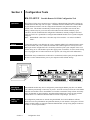
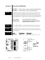
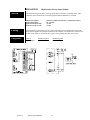
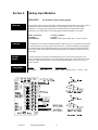
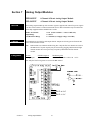
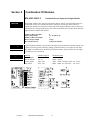
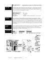
Sixnet_DistributedIO_RD485_user_D301
RemoteTRAK
RS485 Distributed I/O for
Modbus and SIXNET
Systems
Contents at a Glance:
Section 1
General Information
RM-PS-024-01F
3
Section 2
RS485 Wiring
RM-232-485-4U
5
Section 3
Configuration Tools
RM-232-SETUP and Windows Tools
7
Section 4
Discrete Input Modules
RM-8DI2-F, -U and RM-16DI2-H
8
Section 5
Discrete Output Modules
RM-8DO2-F and RM-16DO2-H
11
Section 6
Analog Input Modules
RM-8AI2-F, RM-16AI2-H, RM-8INS
13
Section 7
Analog Output Modules
RM-8AO2-F and RM-4AO2-F
16
Section 8
Combination I/O Modules
RM-4DI2-4DO2-U and RM-4DI2-4AI2-U
17
Section 9
Service Information
Service Information and Product Support
19
Class I, Division 2,
Groups A, B, C, and D
Hazardous Locations
SIXNET • Box 767 • Clifton Park, NY 12065 USA • +1 (518) 877-5173 • FAX +1 (518) 877-8346 • [email protected]
PROTECTED TECHNOLOGY POLICY
SIXNET protects your investment in SIXNET systems with long-term planned technology and our unique Protected
Technology Policy. We will continue to support the specified capabilities of standard SIXNET products for at least five years.
We plan each product improvement and new feature to be upward compatible with existing designs and installations. Our
goals are to make each new software release bring new power to your SIXNET systems and have every existing feature,
applications program and data file continue to work.
We protect your investment even further with a liberal five-year trade-in policy. Exchange standard products for upgraded
versions of the same product to take advantage of new features and performance improvements at any time for five years. A
prorated trade-in allowance will be given for your existing equipment.
SIXNET protects your long-term productivity with state-of-the-art planned technology and continued support.
STATEMENT OF LIMITED WARRANTY
SIXNET, manufacturer of SIXTRAK, VersaTRAK, RemoteTRAK and EtherTRAK products, warrants to Buyer that products
manufactured by SIXNET will be free from defects in material and workmanship. SIXNET’s obligation under this warranty
will be limited to repairing or replacing, at SIXNET’s option, the defective parts within 1 year of the date of installation, or
within 18 months of the date of shipment from the point of manufacture, whichever is sooner. Products may be returned by
Buyer only after permission has been obtained from SIXNET. Buyer will prepay all freight charges to return any products to
the repair facility designated by SIXNET.
This limited warranty does not cover losses or damages that occur in shipment to or from Buyer or due to improper
installation, maintenance, misuse, neglect or any cause other than ordinary commercial or industrial applications, This
limited warranty is in lieu of all other warranties whether oral or written, expressed or implied. SIXNET’s liability shall not
exceed the price of the individual unit which is the basis of the claim. In no event shall SIXNET be liable for any loss of
profits, loss of use of facilities or equipment or other indirect, incidental or consequential damages.
INSTALLATION AND HAZARDOUS AREA WARNINGS
These products should not be used to replace proper safety interlocking. No software-based device (or any other solid-state
device) should ever be designed to be responsible for the maintenance of consequential equipment or personnel safety. In
particular, SIXNET disclaims any responsibility for damages, either direct or consequential, that result from the use of this
equipment in any application.
All power, input and output (I/O) wiring must be in accordance with Class I, Division 2 wiring methods and in accordance
with the authority having jurisdiction.
WARNING – EXPLOSION HAZARD – SUBSTITUTION OF COMPONENTS MAY IMPAIR SUITABILITY FOR CLASS
1, DIVISION 2.
WARNING – EXPLOSION HAZARD – WHEN IN HAZARDOUS LOCATIONS, DISCONNECT POWER BEFORE
REPLACING OR WIRING MODULES.
WARNING – EXPLOSION HAZARD – DO NOT DISCONNECT EQUIPMENT UNLESS POWER HAS BEEN
SWITCHED OFF OR THE AREA IS KNOWN TO BE NONHAZARDOUS.
Note: All information in this document applies to RemoteTRAK I/O, except where otherwise
noted. Refer to the SIXNET I/O Tool Kit software online help system for detailed product
specifications and configuration settings.
RemoteTRAK User Manual
Page 2
Last Revision: March 2001
RemoteTRAK manual.doc
Section 1
General Information
Overview
This manual will help you install and maintain RemoteTRAK I/O. In summary, wiring for power,
communications and I/O is connected to each module’s base. Then, setup choices are entered
using the SIXNET I/O Tool Kit software and the system is ready to run.
Performance
Specifications
These general specifications apply to all RemoteTRAK modules.
Supply Voltage
Modules per RS485 bus
RS485 Isolation
Operating Temperature
Storage Temperature
Humidity
Power
Wiring
9 - 30 VDC, 0.5 Watt typical per module
(25 mA @ 24 VDC – varies by module and load).
32 (use a RM-232-485-4U to drive a total of 128 modules)
1200 Volts RMS (for 1 minute)
-30 to 70 °C
-40 to 85 °C
5 to 95% (non-condensing)
RemoteTRAK modules can be powered from the same DC source that is used to power your I/O
devices. No separate power supply is required. 10 to 30 VDC needs to be applied to terminals 17
and 18 on the base of each module. Some RemoteTRAK modules distribute power or return
connections to I/O terminals for your convenience in making field-wiring connections. Refer to
the wiring diagram for each module for more information.
The RM-PS-024-01F can be used to power your RemoteTRAK modules, instrumentation loops,
and other devices. It operates on 85264 VAC (47-63 Hz) or 120-370 VDC and outputs 24 VDC at
up to 1 A. Refer to the figure below for the proper power connections. Tighten the screw
terminals to a maximum of 3.48 in-lbs.
Section 1
General Information
3
Status LED
Indication
On, with a quick “OFF” BLINK (1.9 seconds ON, .1 seconds OFF) - The module is configured
and fully operational, but has not received a valid request from the host for a time longer than the
specified time out period. A communication time out has occurred.
Full ON - The module is configured, fully operational, and has received communication from the
host device before the timeout period expired. This is the desired LED indication during
system operation.
HALF BLINK (1 second ON, 1 second OFF) - The module is not adequately configured and
requires a download from the SIXNET I/O Tool Kit utility.
Full OFF - There is no power to the module, or the status LED is being turned off intentionally
by SIXNET I/O Tool Kit during the module loading operation.
Off, with a quick “ON” BLINK (1.9 seconds OFF, .1 seconds ON ) - The module failed self-test
at initialization. It will not attempt communication and should be replaced.
Status LED
Wink Feature
Section 1
The “Status” LED may be intentionally winked (10 blinks/ second) by the SIXNET I/O Tool Kit
utility to visually identify the module when other modules are present.
General Information
4
Section 2
RS485 Wiring
Guidelines
RS485 Wiring
RemoteTRAK modules communicate with a master controller (PC, SIXTRAK Gateway,
VersaTRAK, DCS, PLC, etc.) using a two wire RS485 party-line. It is recommended that in
addition to the two signal wires, a shield or ground wire be connected to reference all stations to a
common return. The RS485 port on all RemoteTRAK modules is isolated from its internal
circuitry, local power source, and I/O wiring to improve communications reliability. It is
recommended that only 32 RemoteTRAK modules be connected on an unbuffered RS485 partyline, and that the termination jumper be installed on the last module on the end of a network
segment. Limiting the cabling to two network arms (segments) radiating from the master
controller will yield best signal results.
RM-232-485-4U RS232 to RS485 Four Port Converter
Overview
This interface provides a convenient way to connect RS485 bussed RemoteTRAK I/O modules to
a RS232 port on a master controller. Designed specifically for driving RemoteTRAK modules,
this converter is fully automatic, requiring no user settings. Four RS485 ports are provided to
allow up to 128 I/O modules to be connected in a star configuration (multiple network arms).
Electrical isolation is provided between the RS232 and RS485 ports for increased reliability.
This RS232 to RS485 converter is recommended when:
RemoteTRAK I/O modules need to be connected to an RS232 port on the master controller.
More than 32 RemoteTRAK modules and/or other RS485 devices are to be addressed.
A “star” wiring configuration (more than two network wiring segments) is needed.
Electrical isolation between the RS485 party-line and the RS232 port on the master controller
will increase reliability.
1.
2.
3.
4.
RS232 Wiring
Only the transmit (TD), receive (RD) and common return (GND) signals need be connected in
the RS232 cable. A SIXNET ST-CABLE-PF or other suitable null modem cable may be
connected to the DB9 connector in the face of the module. Alternatively, signals may be
connected to the wiring base as shown in the upcoming diagram. The RM-232-485-4 module
detects message direction and automatically generates a transmitter enable (keying) signal. The
DTR signal is always high (asserted) to provide a pull up for any lines in the master controller
that may need to be tied off.
RS485 Wiring
All four RS485 ports are interchangeable and may each drive up to 32 RemoteTRAK modules. In
addition to the two wire signal pair, it is recommended that a shield or third ground conductor be
connected to the RS485 ground terminal to reference all stations together. All four RS485 ports
are referenced to the same internal signal common (ground), which is electrically isolated from
the RS232 port and DC power input terminals. It is recommended that a jumper wire be
connected between the “RS485(-)” terminal and “Term” terminal if this device is on the end of a
network arm (i.e. it is the last station on the RS485 bus).
Screw Torque
All the screw terminals on the base should be tightened to a maximum of 3.48 in-lbs.
Section 2
RS485 Wiring
5
Section 2
RS485 Wiring
6
Section 3
Configuration Tools
RM-232-SETUP Portable Remote I/O Field Configuration Tool
Operation
This setup tool is the most convenient way to configure a RemoteTRAK I/O module. Unplug any
module and insert this setup tool in its place. Commands from the SIXNET I/O Tool Kit software
in your Windows-based PC store the configuration information into permanent memory in the
module’s base. This module automatically reads the unique serial number stored in the base,
making it unnecessary for you to enter the serial number into the software manually. Upon
reinsertion, the I/O module finds this configuration information, instantly configures itself and
begins to scan I/O. It is permissible to configure RemoteTRAK modules in live systems using this
setup tool.
Note: RemoteTRAK “smart bases” allow hot swap of live modules -- an exclusive SIXNET
feature.
Wiring
Connect this module to your Windows PC using a standard SIXNET ST-CABLE-PF RS232 cable.
Only the transmit (TD), receive (RD) and common return (GND) signals are actively used. The
RS232 port on this configuration tool is electrically isolated to protect your computer in the event
of field wiring errors. This module requires DC supply power on terminals 17 and 18 on the wiring
base it is plugged into. No other connections are required. (I/O wiring will be left undisturbed.)
RS232 Mode
This module always communicates to the host PC at 9600 baud, with no parity and eight data bits.
Be sure to set the communications port on your computer to these default settings.
Alternative
Setup Method
RemoteTRAK modules may also be configured by connecting the RS485 party-line to an RS485
port or RS232 port (through a converter) on your PC. It will be necessary to enter the serial number
found on each module’s base in the SIXNET I/O Tool Kit to enable this setup software to initially
talk to each module. In most situations, setup through the RS485 port can only be done with the
system off-line. Use a RM-232-SETUP module for on-line setup changes. (See above.)
SIXNET I/O
Tool Kit
All configuration parameters are entered using the SIXNET I/O Tool Kit Windows software,
which stores all setup information into permanent memory in each module’s wiring base. No field
jumpers or DIP switches are required on RemoteTRAK module (except wiring jumpers in the base
of some 4 - 20 mA input modules).
Section 3
Configuration Tools
7
Section 4
Discrete Input Modules
RM-8DI2-F
RM-8DI2-U
Overview
8 Discrete Inputs / Counters with Direct Field Wiring Base
8 Discrete Inputs / Counters with Isolated Inputs
The popular field wired (-F) base provides a pre-wired connection to DC power for each of the
eight discrete input channels. For applications which require individually isolated, ground
sinking, or AC inputs, the universal wiring (-U) base is recommended. An input count feature
uses analog input registers to accumulate the positive transitions of each input. More information
on this and other features can be found in the on-line help supplied with the SIXNET I/O Tool
Kit.
Number of Channels
Input Voltage Range
Maximum Count Rate
8 discrete inputs with pulse counter feature
10 - 30 VDC (-F base), 10 - 30 VDC/VAC (-U base)
100 Hz (6000 / minute) each input, plus selectable 2KHz
(120,000 / minute) mode for input 1 only
-F Wiring
The even numbered terminals (2 - 16) on this field wiring ready base are pre-wired to the DC
power (+) terminal. Adjacent pairs of terminals are connected to each input (switch) device.
-U Wiring
A pair of floating terminals is provided for each input to provide channel-to-channel isolation
(floating inputs) and a choice of sourcing (power switching), sinking (ground switching) or AC
signals on each input.
I/O Registers
Function
Discrete Inputs
Counter Inputs
Section 4
SIXNET Registers
X0 - X7
AX0 - AX7
Discrete Input Modules
Modbus Registers
10001 – 10008
30001 - 30008 Unsigned values: 0
8
Å 65,535
Section 4
Discrete Input Modules
9
RM-16DI2-H
Overview
High Density Discrete Input Module
Sixteen discrete inputs accept DC sourcing signals that are all tied to a common return. More
information can be found in the on-line help supplied with the SIXNET I/O Tool Kit.
Number of Channels
Input Voltage Range
Input Current @ 12 VDC
Input Current @ 24 VDC
16 discrete inputs (connected to a common DC source)
10 - 30 VDC
3.5 mA
7.0 mA
-H Wiring
This high density input module provides a single terminal input for each channel. Positive DC
voltage must be applied to an input to indicate an ON condition. All channels are referenced to a
common return which is connected to the negative side (ground) of the DC power source.
I/O Registers
Function
Discrete Inputs
Section 4
SIXNET Registers
X0 - X15
Discrete Input Modules
Modbus Registers
10001 – 10016
10
Section 5
Discrete Output Modules
RM-8DO2-F
Overview
8 Channel High Output Current Module
Eight discrete output channels provide up to 3 Amps DC to motor contactors, valves, and other
loads. Overload and thermal shutdown protection are provided. Each of the eight outputs may
optionally be configured as Time Proportioned Outputs that pulse ON at a duty cycle proportional
to an analog output register value. Typically these TPO outputs are controlled by a PID loop or
other process algorithm in a control program. More information may be found in the on-line help
supplied with the SIXNET I/O Tool Kit.
Number of Channels
Output Voltage Range
Max. Load per Output
Max. Load per Module
Max. Inrush Current
8 discrete outputs connected to a common DC source
10 - 30 VDC
3 Amps
10 Amps
10 Amps (for 100 mS)
-F Wiring
Two terminals, including a ground return, are provided for each output channel. All channels are
powered by a common DC source which is connected to the DC power input terminal.
I/O Registers
Function
Discrete Outputs
TPO Values
TPO Feature
Section 5
SIXNET Registers
Y0 - Y7
AY0 - AY7
Modbus Registers
00001 - 00008
40001 - 40008 0 to 100% ON: 0
Å 32767
Time proportioned outputs pulse ON and OFF with a duty cycle proportional to an analog value
stored in an analog output register. TPO outputs are a low cost way to get smooth proportional
control of heaters and other process variables. Typically, TPO analog output registers are assigned
to the output of PID or other control logic in an ISaGRAF or other program. Use the SIXNET I/O
Tool Kit to set pulse cycling as fast as 10 mS or as slow (many minutes) as your system dynamics
require. Each output may be individually configured as a TPO or ordinary discrete output.
Discrete Output Modules
11
RM-16DO2-H
Overview
High Density Discrete Output Module
Sixteen discrete outputs provide power for loads up to 1 Amp. This module does not provide over
current protection or TPO capabilities. More information can be found in the on-line help
supplied with the SIXNET I/O Tool Kit.
Number of Channels
Output Voltage Range
Max. Load per Output
Max. Load per Module
Max. Inrush Current
16 discrete outputs connected to a common DC source
10 - 30 VDC
1 Amp
10 Amps
5 Amps (for 100 mS)
-H Wiring
A single terminal is provided for each output channel. All outputs are powered from the DC
power terminal. All channels are referenced to a common return which is connected to the
negative side (ground) of the DC power source.
I/O Registers
Function
Discrete Outputs
Section 5
SIXNET Registers
Y0 - Y15
Discrete Output Modules
Modbus Registers
00001 - 00016
12
Section 6
Analog Input Modules
RM-8AI2-F
Overview
8 Channel 4-20 mA Analog Inputs
Eight 4-20 mA inputs provide 16 bit high resolution analog measurements. Each input circuit in
this module provides a field selectable choice of providing DC power (for loop powered
transmitters) or accepting a ground return (from internally powered instruments). More
information can be found in the on-line help supplied with the SIXNET I/O Tool Kit.
Number of Channels
Input Range
Input Impedance
8 (16 bit resolution)
4 - 20 mA
100 ohms Note: input voltage drop = 2 volts at 20 mA
-F Wiring
Two terminals are provided for each input channel. Either DC power or ground may be provided
for each input device by setting a jumper inside the base. (Access these jumpers by unplugging
the module and then opening the hinged door in the wiring base.) Refer to the diagram below.
Please be sure to provide a suitable instrumentation ground to avoid measurement errors due to
ground loops.
Current
Shunts
Precision 100 ohm current shunts, beneath the hinged access door in the wiring base, pass
current and maintain loop integrity even if the module is unplugged. A spare shunt is provided
and may be simply inserted in place of any socketed shunt that open circuits as a result of a
current overload.
I/O Registers
Function
Analog Inputs
Section 6
SIXNET Registers
AX0 - AX7
Analog Input Modules
Modbus Registers
30001 - 30008 Bipolar values: -32768
13
Å 32767
RM-16AI2-H
Overview
High Density 4-20 mA Analog Input Module
Sixteen 4-20 mA inputs provide 16 bit high resolution analog measurements. More information
can be found in the on-line help supplied with the SIXNET I/O Tool Kit.
Number of Channels
Input Range
Input Impedance
16 (16 bit resolution)
4 - 20 mA
100 ohms Note: input voltage drop = 2 volts at 20 mA
-H Wiring
A single input terminal is provided for each measurement channel. Care must be taken to
externally provide a suitable instrumentation ground for these single ended input circuits.
Current
Shunts
Precision 100 ohm current shunts, beneath the hinged access door in the wiring base, pass
current and maintain loop integrity even if the module is unplugged. A spare shunt is provided
and may be simply inserted in place of any socketed shunt that open circuits as a result of a
current overload.
I/O Registers
Function
Analog Inputs
Section 6
SIXNET Registers
AX0 - AX15
Analog Input Modules
Modbus Registers
30001 - 30016 Bipolar values: -32768
14
Å 32767
RM-8INS-U
Overview
Instrumentation Analog Input Module
Eight isolated input channels provide 16 bit high resolution analog measurements. More
information can be found in the on-line help supplied with the SIXNET I/O Tool Kit.
Number of Channels
8 (16 bit resolution)
Input Ranges
JKERTBCNS Thermocouples, 62 mV to 10V, 4 - 20 mA
Input Impedance (4-20 mA)
100 ohms Note: input voltage drop = 2 volts at 20 mA
Input Impedance (other ranges) 200K Ohms
-U Wiring
Two input terminals are provided for each measurement channel. Channel to channel isolation
is provided.
Current
Shunts
Precision 100 ohm current shunts, beneath the hinged access door in the wiring base, pass
current and maintain loop integrity even if the module is unplugged. A spare shunt is provided
and may be simply inserted in place of any socketed shunt that open circuits as a result of a
current overload.
I/O Registers
Function
Analog Inputs
Section 6
SIXNET Registers
AX0 – AX7
Analog Input Modules
Modbus Registers
30001 – 30008 Bipolar values: -32768
15
Å 32767
Section 7
Analog Output Modules
RM-8AO2-F
RM-4AO2-F
Overview
8 Channel 4-20 mA Analog Output Module
4 Channel 4-20 mA Analog Output Module
These analog output modules provide 4-20 mA signals as proportional control for process signals
or to drive chart recorders or other measurement devices. More information may be found in the
on-line help supplied with the SIXNET I/O Tool Kit.
Number of Channels
Output Range
Load Resistance Range
-F Wiring
Two terminals are provided for each output channel. Outputs are directly powered from the DC
power connected to this module.
Note:
I/O Registers
4 or 8 (13 bit resolution -- 0.03% of full scale)
4 - 20 mA
0 - 750 ohms (at a supply voltage of 24 VDC)
Both modules use a RM-8AO2-FB wiring base. Only the first four channels are used on
the RM-4AO2-F. System capacity may be increased by plugging a RM-8AO2-M eight
channel module into a base previously occupied by a RM-4AO2-M four channel
module.
Function
Analog Outputs
SIXNET Registers
AY0 - AY7
Modbus Registers
40001 - 40008 Positive values: 0
Note: Only the first four registers are used on the RM-4AO2-F.
Section 6
Analog Input Modules
16
Å 32767
Section 8
Combination I/O Modules
RM-4DI2-4DO2-U
Overview
Combined Discrete Input and Output Module
This module combines four discrete inputs and four discrete outputs. An input count feature uses
analog input registers to accumulate the positive transitions of each input. Each of the four
outputs may optionally be configured as Time Proportioned Outputs that pulse ON at a duty cycle
proportional to an analog output register value. More information can be found in the on-line help
supplied with the SIXNET I/O Tool Kit.
Number of Discrete Inputs
Input Voltage Range
Number of Discrete Outputs
Max. Load per Output
Max. Inrush Current
4
10 - 30 VDC/VAC
4
1 Amp
5 Amps (for 100 mS)
-U Wiring
A pair of floating terminals is provided for each input to provide channel-to-channel isolation and
a choice of sourcing (power switching), sinking (ground switching) or AC signals on each input.
The outputs all switch power from the DC power input terminal. A ground return for each output
is provided for your convenience.
I/O Registers
Function
Discrete Inputs
Discrete Outputs
Counter Inputs
TPO Values
Section 8
SIXNET Registers
X0 - X3
Y0 - Y3
AX0 - AX3
AY0 - AY3
Combination I/O Modules
Modbus Registers
10001 – 10004
00001 – 00004
30001 - 30004 Unsigned values: 0
40001 - 40004 0 to 100% ON: 0
Å 65,535
Å 32767
17
RM-4DI2-4AI2-U
Overview
Combined Discrete Input and Analog Input Module
This module combines four discrete inputs and four analog inputs. A discrete input count feature
uses analog input registers to accumulate the positive transitions of each input. The four analog
inputs accepts signals from internally powered or loop powered devices. More information can be
found in the on-line help of the SIXNET I/O Tool Kit.
Number of Discrete Inputs
Input Voltage Range
Number of Analog Inputs
Input Range
Input Impedance
4
10 - 30 VDC
4
4 - 20 mA
100 ohms
Note: input voltage drop = 2 volts at 20 mA
-U Wiring
A pair of floating terminals is provided for each discrete input to provide channel-to-channel
isolation and a choice of sourcing (power switching), sinking (ground switching) or AC signals on
each input. Two terminals are provided for each analog input channel. Either DC power or ground
may be provided for each input device by setting a jumper inside the base. (Access these jumpers by
unplugging the module and then opening the hinged door in the wiring base.) Refer to the diagram
below. Please be sure to provide a suitable instrumentation ground to avoid measurement errors due
to ground loops.
Current
Shunts
Precision 100 ohm current shunts, beneath the hinged access door in the wiring base, pass current
and maintain loop integrity for each of the four analog input channels even if the module is
unplugged. A spare shunt is provided and may be simply inserted in place of any socketed shunt
that open circuits as a result of a current overload.
I/O Registers
Function
Discrete Inputs
Analog Inputs
Counter Inputs
Section 8
SIXNET Registers
X0 - X3
AX0 - AX3
AX4 - AX7
Combination I/O Modules
Modbus Registers
10001 - 10004
30001 - 30004 Bipolar values: -32768 32767
65,535
30005 - 30008 Unsigned values: 0
Å
18
Å
Section 9
Service
Information
Service Information
We sincerely hope that you never experience a problem with any SIXNET product. If you do need
service, call SIXNET at (518) 877-5173 and ask for Applications Engineering. A trained
specialist will help you to quickly determine the source of the problem. Many problems are easily
resolved with a single phone call. If it is necessary to return a unit to us, an RMA (Return Material
Authorization) number will be given to you.
SIXNET tracks the flow of returned material with our RMA system to ensure speedy service. You
must include this RMA number on the outside of the box so that your return can be processed
immediately.
The applications engineer you are speaking with will fill out an RMA request for you. If the unit
has a serial number, we will not need detailed financial information. Otherwise, be sure to have
your original purchase order number and date purchased available.
We suggest that you give us a repair purchase order number in case the repair is not covered under
our warranty. You will not be billed if the repair is covered under warranty.
Please supply us with as many details about the problem as you can. The information you supply
will be written on the RMA form and supplied to the repair department before your unit arrives.
This helps us to provide you with the best service, in the fastest manner. Normally, repairs are
completed in two days. Sometimes difficult problems take a little longer to solve.
If you need a quicker turnaround, ship the unit to us by air freight. We give priority service to
equipment that arrives by overnight delivery. Many repairs received by mid-morning (typical
overnight delivery) can be finished the same day and returned immediately.
We apologize for any inconvenience that the need for repair may cause you. We hope that our
rapid service meets your needs. If you have any suggestions to help us improve our service, please
give us a call. We appreciate your ideas and will respond to them.
For Your Convenience:
Please fill in the following and keep this manual with your SIXNET system for future reference:
P.O. #:__________________ Date Purchased: ___________________
Purchased From:______________________________________________
Product
Support
To obtain support for SIXNET products, call SIXNET and ask for applications engineering. Our
phone numbers are:
+1 (518) 877-5173 Office
+1 (518) 877-8346 Fax
e-mail: [email protected]
Our mailing address:
SIXNET
Ushers Rd.
P.O. Box 767
Clifton Park, NY 12065
Section 9
Service Information
19