1
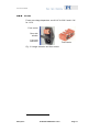
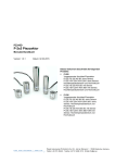
® Advanced Test Equipment Rentals www.atecorp.com 800-404-ATEC (2832) E stablished 1981 PZ 67E User Manual E-463 Release: 1.2.0 3-Channel HVPZT Amplifier Date: 2004-12-07 This document describes the following product(s): E-463.00 3-Channel HVPZT Amplifier © Physik Instrumente (PI) GmbH & Co. KG Auf der Römerstr. 1 ⋅ 76228 Karlsruhe, Germany Tel. +49 721 4846-0 ⋅ Fax: +49 721 4846-299 [email protected] ⋅ www.pi.ws Declaration of Conformity according to ISO / IEC Guide 22 and EN 45014 Manufacturer: Manufacturer´s Address: Physik Instrumente (PI) GmbH & Co. KG Auf der Römerstrasse 1 D-76228 Karlsruhe, Germany The manufacturer hereby declares that the product Product Name: Model Numbers: Product Options: High-Voltage Amplifier E-463.00 none conforms to the following EMC Standards and normative documents: Electromagnetic Emission: EN 61000-6-3, EN 55011 Electromagnetic Immunity: EN 61000-6-1 Safety (Low Voltage Directive) : EN 61010-1 August 24, 2004 Karlsruhe, Germany Dr. Karl Spanner President Copyright 1999–2004 by Physik Instrumente (PI) GmbH & Co. KG, Karlsruhe, Germany. The text, photographs and drawings in this manual enjoy copyright protection. With regard thereto, Physik Instrumente (PI) GmbH & Co. KG reserves all rights. Use of said text, photographs and drawings is permitted only in part and only upon citation of the source First printing 2004-12-07 Document Number PZ 67E, Release 1.2.0 E-463_User_PZ67E120.doc This manual has been provided for information only and product specifications are subject to change without notice. About this Document Users of this Manual This manual is designed to help the reader to install and operate the E-463 3-Channel HVPZT Amplifier. It assumes that the reader has a fundamental understanding of basic electronics and applicable safety procedures. The manual describes the physical specifications and dimensions of the E-463 3-Channel HVPZT Amplifier as well as the procedures which are required to put the associated motion system into operation. Updated releases are available via FTP or email: contact your Physik Instrumente sales engineer or write [email protected]. Conventions The notes and symbols used in this manual have the following meanings: WARNING Calls attention to a procedure, practice or condition which, if not correctly performed or adhered to, could result in injury or death. DANGER Indicates the presence of high voltage (> 50 V). Calls attention to a procedure, practice or condition which, if not correctly performed or adhered to, could result in injury or death. CAUTION Calls attention to a procedure, practice, or condition which, if not correctly performed or adhered to, could result in damage to equipment. ! Contents 1 Introduction 1.1 1.2 1.3 2 Safety Precautions .....................................................................2 Features .....................................................................................3 Actuator Types and Terminology ...............................................3 1.3.1 1.3.2 Bipolar Actuators........................................................................ 3 Unipolar Actuators...................................................................... 3 2 Quick Start 5 3 Working Principle 8 4 Technical Data 9 4.1 4.2 Front Panel Operating Elements ..............................................10 Rear Panel ...............................................................................10 4.2.1 4.2.2 5 Voltage Selector....................................................................... 10 Fuses........................................................................................ 11 E-463 Frequency Response 12 Introduction 1 Introduction E-463.00 HVPZT Amplifiers are bench-top amplifiers for HighVoltage Piezoelectric Translators (HVPZTs). The device contains three independent amplifiers capable of outputting and sinking a peak current of 4 mA and an average current of 3 mA each. One side of the output is grounded, the other ranges from 0 to -1500 V. Negative polarity was chosen to comply with the requirements of common HVPZTs. The output voltage can be set either manually via a 10-turn potentiometer or by analog control signals, or both in combination. Three 3½-digit LED displays indicate the output voltage of the three channels. 1.1 Safety Precautions Physik Instrumente (PI) advises you to read this important information: DANGER Be aware that the E-463 is a High Voltage Amplifier capable of outputting voltages up to 1500 Volts. The high output power may cause electrical shock or serious injuries if the device is handled improperly. To avoid danger, follow the instructions below: Do not open the chassis while the line power cord is connected! Do not touch any part that may be connected to the high voltage output! Make sure that the metal casings of all PZT actuators connected to the HV output are properly grounded. www.pi.ws E-463 PZ 67E Release 1.2.0 Page 2 Introduction WARNING PZTs Sensitive Polarity to Overvoltage or Reverse Exposing some PZTs to voltages too far outside their operating range will destroy the active element in the actuator. Remember that the active element has only two terminals and is aware only of the potential difference between them. A PZT with -250 V on the negative lead and 0 V on the positive lead sees +250 V. Make sure that both the polarity and the voltage as seen by the PZT are within the allowable range. 1.2 1.3 Features Manual control mode: 10-turn potentiometer External control mode: analog signal, 10-volt-wide range, manual offset Real-time output LED display for each channel Actuator Types and Terminology The HV actuators that can be connected to the controller have two conductors for the drive voltage. The displacement of the actuator depends only on the (signed) voltage difference between these two leads. It is important to understand the type of actuator being connected. 1.3.1 Bipolar Actuators Bipolar actuators can be driven with either a positive or negative potential difference between the drive leads. Because the E-463 can supply only one output polarity, it is not particularly suited for bipolar actuators 1.3.2 Unipolar Actuators It is important to understand the designations “positive” and “negative” when used with unipolar actuators. These designations refer to the placement (and perhaps the labeling) www.pi.ws E-463 PZ 67E Release 1.2.0 Page 3 Introduction of conductors on the piezo or in the coaxial connecting cable. They originate with the idea that, if one side of the actuator is tied to ground, it is “safer” to have the “dangerous” voltage “farther away” from the user, e.g. in the core of coaxial cable, or not at the end of a stack. Unipolar piezos can withstand only limited reverse voltages, typically less than 25% of the full operating range. Forward voltage always has the positive terminal at a higher potential than the negative terminal, even if the actuator is referred to as a “negative” type. Since so-called “-1500 V” unipolar actuators were designed with the idea that the positive terminal would be connected to 0 V and the negative terminal range to -1500 V, there is some confusion when it comes to speaking about the voltage “applied to” and “seen by” the actuator. If you put -200 V on the negative terminal and 0 on the positive terminal, you can be tempted to say that you are “applying” “-200 V” to the actuator. For the actuator, however, this is the same as having 0 V on the negative lead and +200 V on the positive lead: in both cases, it sees a +200 V potential difference. Some actuators actually use the labels “0 V” and “-1000 V” on the corresponding leads. www.pi.ws E-463 PZ 67E Release 1.2.0 Page 4 Quick Start 2 Quick Start If you order the actuator and controller together, and/or provide PI with sufficient information about your application, the actuator connector will be wired as required. If you are connecting other actuators or wiring your own connector, read the discussion of actuator type (Section 1.3) carefully and any documentation that came with the actuator. WARNING PZTs Sensitive Polarity to Overvoltage or Reverse Exposing some PZTs to voltages too far outside their operating range will destroy the active element in the actuator. Remember that the active element has only two terminals and is aware only of the potential difference between them. A PZT with -250 V on the negative lead and 0 V on the positive lead sees +250 V. Make sure that both the polarity and the voltage as seen by the PZT are within the allowable range. DANGER Be aware that the E-463 is a High Voltage Amplifier capable of outputing voltages up to 1500 Volts. The high output power may cause electrical shock or serious injuries if the device is handled improperly. To avoid danger, follow the instructions below: Do not open the chassis while the line power cord is connected! Do not touch any part that may be connected to the high voltage output! Make sure that the metal casings of all PZT actuators connected to the HV output are properly grounded. www.pi.ws E-463 PZ 67E Release 1.2.0 Page 5 Quick Start First check the unit in manual operating mode as follows: 1 Read the Danger Warning above. Perform the following steps with care. 2 Being careful not to exceed allowable force limits, mount the PZT actuators for your application (see the PZT Mounting Guidelines included with the actuators on a separate sheet) 3 Make sure the E-463 power supply is set to allow operation at the proper voltage range. Two ranges are available: from 100 to120 V and from 220 to240 VAC. The line fuses need to be replaced when the supply voltage range setting is changed (see p. 10 for details). 4 Turn the DC-OFFSET potentiometer to 0, i.e. counterclockwise (CCW) to the hard stop. 5 With the amplifier still powered down, connect the actuators to the HV output LEMO connectors on the E-463 front panel 6 Connect the line cord and switch the power on. 7 Being careful not to exceed the maximum voltage rating of the connected PZT, turn the corresponding DC-offset potentiometer slowly CW. The voltage changes, as indicated on the corresponding display. The displacement of the PZT depends on its expansion ratio, µm/V. 8 Before turning off the E-463, set all channels to zero output (turn the DC-Offset potentiometers full CCW and make sure the Control IN signals are at 0 V). The above procedure assures that the system is working correctly in manual mode. If you will be operating with one or more external control signals (static or dynamic), continue as follows: 9 Make sure that the control signal is never below -6.6 V or above +10 V, and varies by at most 10 V. 10 Bring the control signal to its minimum level and connect it to Control IN. 11 Use the corresponding DC-offset potentiometer to adjust the output to the level desired (usually 0 V) www.pi.ws E-463 PZ 67E Release 1.2.0 Page 6 Quick Start ! CAUTION PZT Damage Make sure not to exceed the allowed PZT operating voltage! 12 When the control signal is varied (by at most 10 V), the output will change by an amount reflecting the gain factor of -150. Note that this covers a wider range than can be covered in manual operation. 13 Repeat steps 9 to 12 for each channel you wish to connect. www.pi.ws E-463 PZ 67E Release 1.2.0 Page 7 Working Principle 3 Working Principle The output voltage is determined by the position of the 10-turn DC-offset potentiometer in combination with the voltage on the Control Input BNC socket. If Control In is held at 0 V, the output voltage be varied manually with the potentiometer in the range of 0 to -1000 V. This is sometimes called manual operation. With the DC-offset potentiometer set to 0 (full CCW), the output voltage is controlled by an analog signal applied to the BNC input ranging from 0 to +10 V. Multiplying by the gain factor of -150, an output voltage range from 0 to -1500 V results. When used together with Control IN, the DC-offset potentiometer effectively allows shifting the 10-volt-wide input voltage range inside the boundaries of -6.66 V and +10 V. Example 1: A low frequency (< 1 Hz) sinusoidal signal with an amplitude of 0 to +5 V is applied to the CONTROL INPUT socket. The resulting output is a sinusoidal signal with an amplitude of 0 to -750 V. Example 2: A function generator with a -2.5 to +2.5 V (peak-peak: 5V) sinusoidal signal is connected to the CONTROL INPUT socket. The resulting output will be clipped for negative inputs, because the E-463 can not output positive voltages (negative gain!). The actual output is the negative half of the sine wave with peak value of -375 V (2.5 V multiplied by a gain factor of -150). In order to get the full sine wave, the input can be offset with the DC-OFFSET potentiometer by 2.5 V. The resulting output is a sinusoidal signal with an amplitude of 0 to -750 V (peakpeak), like in example #1. www.pi.ws E-463 PZ 67E Release 1.2.0 Page 8 Technical Data 4 Technical Data www.pi.ws Function: High-voltage DC power amplifier Application: Driving up to 3 HVPZTs manually or by external analog signals. Channels: 3 Output Voltage Range: 0 to -1500 V Output Polarity: negative Peak Current: 4 mA (for < 5 ms) Max. Average Output Current: 2 mA (for > 5 ms) Peak power: 6 W (for < 5 ms) Max. Average Power: 3 W (for > 5 ms) Control Voltage Input: 10-volt maximum variation within -6.6 to +10 V range Voltage Gain: -150 ±1 Input Impedance: 1 M-ohm Display: 3 3½-digit LED displays Control input sockets: 3 BNC PZT output sockets: 3 LEMO ERA.0S.250.CTL Line Voltage: 110 - 120 or 220 - 240 VAC, selectable (fuse change required) Fuse: 0.8 A for 230 V operation, 1.6 A for 115 V operation, slow blow fuses required Dimensions: 288 x 235 x 103 mm (HxWxD) Weight: 4.3 kg Operating Temperature +5°C to +50°C (over 40°C, max. av. power derated 10%) E-463 PZ 67E Release 1.2.0 Page 9 Technical Data 4.1 Front Panel Operating Elements Fig. 1: E-463 Front panel layout 4.2 3 DC-Offset Potentiometers, 10-turn, one for each channel 3 Control voltage Input sockets (BNC), one for each channel 3 High-voltage output sockets (LEMO, 0 to 1500V) one for each channel 3 3½-digit LED display for output voltages Rear Panel The rear panel contains only the line power connection, voltage range selector, off-on rocker switch and the line fuse assembly. 4.2.1 Voltage Selector Two ranges are available (220-240 V or 110-120 V). Units are delivered set to the range PI believes prevalent in your country, unless otherwise requested. Selected value is visible in window (see figures). To change selection, pry out and re-orient fuse carrier. Fuses will also need to be replaced. www.pi.ws E-463 PZ 67E Release 1.2.0 Page 10 Technical Data 4.2.2 Fuses Fuses are voltage dependent: use 0.8 A* for 230 V and 1.6 A* for 115 V. Fuse carrier Door with window Line cord connector Fuse carrier Fig. 2: Voltage selection and fuse access * www.pi.ws slow blow fuses required E-463 PZ 67E Release 1.2.0 Page 11 E-463 Frequency Response 5 E-463 Frequency Response Fig. 3: E-463, frequency response with various PZT loads. Values shown are capacitance in nF, measured in actual PZT. www.pi.ws E-463 PZ 67E Release 1.2.0 Page 12