1
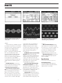
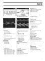
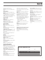
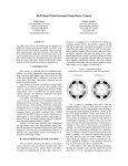
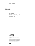
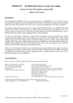
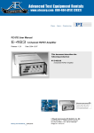
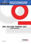
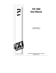
®
Advanced Test Equipment Rentals
E stablished 1981
www.atecorp.com 800-404-ATEC (2832)
Models 296 and 295
50 MS/s Synthesized Multichannel Arbitrary
Waveform Generators
◆
Up to 4 Independent Channels
◆
10 Standard Functions (sine to 20 MHz,
square to 25 MHz)
◆
Up to 50 MS/s Sampling with 12-Bit
Vertical Resolution
◆
Waveform Sequencing of up to 4,096
Segments (Model 296 only)
◆
Frequency Control of Individual Sequence
Segments (Model 296 only)
◆
16-Bit Digital Output to 50 MS/s (Model
296 only)
◆
Optional 100 Vpp Output
◆
Versatile Interchannel Triggering,
Summing and Phase Control
◆
Frequency Sweep
◆
Amplitude and Suppressed Carrier
Modulation
◆
Graphical User Interface
◆
Front Panel Waveform Creation/Editing
Tools
◆
Floppy Disk Drive
◆
GPIB and RS-232 Interfaces
◆
Compatible with Waveform DSP
◆
SCPI Compatible
M
odels 296 and 295 combine sophisticated performance with ease of use in
a way previously not available in
arbitrary waveform generators. Model 295 is
the basic model. Model 296 adds advanced
waveform sequencing capability up to
4,096 waveform segments for complex
waveform generation. It also provides a 16
bit digital output on each channel.
Both models can contain up to four
separate channels. When run independently,
each channel is essentially a stand-alone
arbitrary waveform generator. When in
master/slave mode, phase relationships
between channels can be set by the user.
Each channel outputs 15 Vp-p (into 50 Ω
load) at 50 MS/s sampling frequency
maximum or can output 100 volts peak-topeak when Option 007 is installed. Each
channel has a high-speed clock output that
runs at a maximum of 100 MHz.
Arbitrary waveforms can be created and
stored to nonvolatile RAM or on the
standard MS-DOS™ compatible 3.5-inch,
high-density disk drive. In addition, ten
commonly used synthesized functions are
built in.
The graphic user interface greatly
simplifies creating and editing waveforms,
which can be viewed on an oscilloscope. A
mouse (provided) is used to draw on a scope
when creating waveforms and to make
selections on the graphical interface when
setting up the instrument.
Arbitrary waveforms may be created from
the front panel using the mouse and any of
four modes: free hand, line draw, line list,
and mathematical expressions. In addition,
extensive waveform editing tools enable the
user to control waveform shapes precisely.
The editing tools make it easy to modify
existing waveforms. This is particularly
useful in such applications as characterization testing. For instance, amplitude may be
modified continually in order to characterize
performance of the unit under test. For more
complex applications, waveform linking,
looping and sequencing allow users to create
long, complex waveforms.
Versatile interchannel capabilities are
provided. An internal summing bus allows
waveforms from multiple channels to be
summed together. Other interchannel
capabilities include setting phase shift
between channels, linking waveforms
together and triggering one channel from
another.
Waveforms, sequences, and entire
instrument set-ups can be stored in the
internal nonvolatile 60 kB RAM or on disk
via the disk drive.
It’s Easy to Create Any Waveform. Models
296 and 295 take the limits off your ability to
simulate the signals you are faced with in the
real world.
Built-in features make interactive
control of complex waveforms and instrument set-up simple. Waveforms can be
created, copied, edited, downloaded, and
sequenced, all with a few clicks of the
mouse. The 296 and 295 provide a complete
set of tools that enables you to specify all
kinds of waveforms in a number of ways,
from precise mathematical description to
“what-if” freehand sketching. And modifying waveforms is a snap with tools such as
Vertical Resize and Vertical Move. The
sophisticated user interface gives you access
to all the power of the 296 and 295, with a
flexibility in waveform creation never before
5
Model 296
Typical math expression screen.
Scope Edit screen.
Summing screen.
Amplitude modulated signal generated by the
expression shown on the math expression
screen above.
Scope shows waveforms created with Line
Draw/Line List (top) and Freehand Draw
(bottom).
Scope illustrates summing. Top: Clean square
wave. Middle: Noise. Bottom: Summed
waveform (square wave with noise).
tude and time value. For other kinds of
applications, Freehand Draw gives the
flexibility of using the mouse to draw a
waveform on the oscilloscope in much the
same way as with a pencil on paper. This
makes tasks like inserting spikes on
waveforms easy.
Sum Multiple Channels to Create Complex
Waveforms. With the internal analog
sumbus, you can sum waveforms from two
channels together and output the sum as a
complex or modulated waveform. The
optional high voltage and external summing
module allows three channels and an
external signal to be summed.
Create Long, Complex Waveforms with
Linked Sequence Operation. Up to 4,096
waveforms can be linked together with the
Model 296. Up to 4 waveforms can be
linked together with the Model 295. Loop
count and advance conditions for each
waveform are user programmable.
Trigger Operation. Each channel has its
own internal trigger generator and external
trigger input. Multiple channel triggering
and versatile interchannel triggering are also
provided.
More Tools Make Editing Easy. Models
296 and 295 give you easy ways to modify
waveforms you’ve created. For example, you
can copy and insert portions of existing
waveforms, move individual waveform
points, and increase or decrease the
amplitude of all or part of the waveform.
Digital Output (296 only). Each channel
provides a 16-bit digital output programmable to 50 MHz.
available.
An internal memory of 60 kB is provided
for storing the waveforms you create. Storing
waveforms created or captured elsewhere is
no problem either. Simply download
waveforms over the GPIB or RS-232
interface or through the standard 3.5-in disk
drive. You can download waveforms
generated in Wavetek’s WaveForm DSP
arbitrary waveform creation software or
directly from a DSO (with Option 005). Or
use the disk drive to load ASCII files
generated from spreadsheet programs such
as Microsoft Excel® or Borland’s Quattro
Pro®.
Use Math Expressions. You can create
waveforms with mathematical precision by
entering math expressions using the
numerical keys on the front panel.
Use Line Draw/Line List and Freehand
Draw. For waveforms with straight lines, as in
pulse or digital applications, Line Draw
allows you to use the mouse to draw the
lines on an oscilloscope. Lines may also be
created using Line List, which allows you to
enter the vertices of each line with ampli-
Specifications
NOTE: Specifications apply after a 20-minute warm-up.
Standard Waveforms
Sine, square, triangle, pseudo-random noise,
positive ramp, negative ramp, positive haversine,
negative haversine, sin x/x and DC.
6
Model 296
Digital Output (296 only)
16-bit differential ECL updated at up to 50 MHz.
Frequency Range: 0.2 Hz to 50 MHz
Resolution: 5 digits or 0.1 mHz
Screen shows waveforms, loop counts, and
advance conditions in a typical sequence.
Screen shows typical trigger set-up. In this
case, channel 2 will trigger channel 1.
Clock Output (Each channel)
Range: 0.2 Hz to 100 MHz
Resolution: 5 digits or 0.1 mHz
Accuracy: < ± 2 ppm over temp range of 0 °C to
50 °C using internal reference
Amplitude
Range: 0 to 15 Vp-p into 50Ω,
0 to 30 Vp-p into >10kΩ
Note: Maximum amplitude is 100 Vpp when option 007 is installed
Scope shows four waveforms linked in a
sequence.
Frequency Range
Sine: 1 mHz to 20 MHz
Square: 1 mHz to 25 MHz
Haversines: 1 mHz to 20 MHz
All Others: (25 pt.waveform) 1 mHz to 2 MHz
Resolution:
8 digits limited by 1 mHz,
5 digits for frequencies > 20 MHz
Accuracy:
< ± 2 ppm over temperature range of 0 °C to ±50
°C using internal reference
Waveform Quality
Square Transition Time:
For ≤10 Vp-p: <9.0 ns
For > 10 Vp-p: <9.5 ns
Square Aberrations:<5% ± 20 mV
Square Symmetry (0 °C to ±50 °C) :
< 10 MHz: 50 % ± 1 %
≥ 10 MHz: 50 % ± 2 %
Square cycle to cycle time jitter:
< 0.4% peak to peak
Sine Distortion: (Elliptic filter selected)
<100 kHz, ≤ 15 Vp-p: No harmonic > -55 dBc
<100 kHz, ≤ 10 Vp-p: No harmonic > -60 dBc
<5 MHz, ≤ 10 Vp-p: No harmonic > -45 dBc
<5 MHz, >10 Vp-p: No harmonic > -40 dBc
<20 MHz, ≤ 10 Vp-p: No harmonic > -35 dBc
Scope shows interchannel triggering from the
screen above.
<20 MHz, >10 Vp-p: No harmonic > -28 dBc
Intermodulation Products (Spurs), (Elliptic filter
selected):
<5 MHz: no spur > - 60 dBc
<10 MHz: no spur > - 40 dBc
<20 MHz: no spur > - 35 dBc
SSB Phase Noise at 20 MHz:(Standard Sine):
<-70 dBc/Hz at 100 Hz offset
<-70 dBc/Hz at 1 kHz offset
<-80 dBc/Hz at 10 kHz offset
<-105 dBc/Hz at 100 kHz offset
<-120 dBc/Hz at 1 MHz offset
Arbitrary Waveforms
Max. number of user defined waveforms: 450
Resolution
Horizontal Resolution (296): 128k points
standard (512k points optional), minimum
waveform size 5 points
Horizontal Resolution (295): 32k points standard
(128k/512k points optional), minimum waveform
size is 5 points
Vertical Resolution: 12 bits (4096 points)
Sampling Frequency
Range: 0.2 S/s to 50 MS/s
Resolution: 5 digits or 0.1 mHz
Accuracy: < ± 2 ppm over temp. range of 0°C to
50°C using internal reference
Resolution: 3.5 digits
Monotonicity: 0.2%
Sinewave Flatness (relative to 1 kHz amplitude,
Elliptic filter selected, non sweep modes):
< 5 MHz, 25°C ± 10°C: ± 2 %
< 5 MHz, 0 to 50°C: ± 5 %
< 20 MHz, 25°C ± 10°C: ± 5 %
< 20 MHz, 0 to 50°C: ± 10 %
Accuracy: ±1%
Offset
Range: ±7.5 Vdc into 50Ω, ± 15 Vdc into >10 kΩ
Resolution: 3.5 digits
Accuracy: ±1%
Filters (user selectable):
20 MHz 4 pole Bessel
20 MHz 7 pole, 6 zero Elliptic
Operational Modes
Continuous: Output runs continuously
Triggered: Output is quiescent until triggered by
selected trigger source, then generates the number
of cycles set by the trigger count.
Gated: Output is quiescent until gate (trigger)
signal goes true. Output is continuous for duration
of gate signal.
Frequency Sweep: Standard functions and
arbitrary waveforms may be swept from 1 mHz to 20
MHz.
Trigger (Burst) Count:
For waveforms: 1 to 1,048,575
For sequences: 1 to 65,536
Note: Triggered and Gated limited to 10 MHz
waveform frequency. Sweep frequencies limited to
< 20 MHz.
7
Model 296
Frequency Sweep
With 80 help screens available at the push of a
button; you don’t have to find the user manual
when you need information.
Sequence Operation
Linked sequence mode provides the ability to link
multiple user-defined waveforms together into a
long and complex waveform sequence. Any userdefined waveform may be assigned as a segment in
the sequence. Each segment can be assigned a
unique loop count, start mode, advance mode and
sample frequency. With the 296, a 16-bit value or
“tag” unique to each segment drives the Digital
Output, the lower 12 bits drive the Segment DAC.
Two channels may be linked together via inter
channel triggering and summing to double the
effective sequence length.
Number of Waveform Segments (296, per
channel): 2 to 4096
Number of Waveform Segments (295, per
channel): 2 to 4
Segment Loop Count: 0 to 1,048,576 programming a 0 indicates continuous repetition.
Start Conditions: Automatic or selected start
trigger event
Advance Conditions: Advance on completion of
segment loop count. Advance on trigger.
Segment Clock Ratio (Model 296 only): The
clock ratio determines the ratio between the
programmed raster clock period and the sample
period of each point in the segment. Programmable
from 1 to 65,535.
Segment Tag (Model 296 only):
The segment tag is a 16-bit value associated with
the playback of the segment. All 16-bits of the
segment tag appear on the digital output connector
while the segment is active. The lower 12-bits of the
segment tag drive the secondary DAC.
Sequence Start Conditions
The playback of a sequence may be automatically
initiated or triggered.
Sequence Loop Count
The sequence loop count determines the number of
time the sequence will repeat after a triggered start.
Programmable from 1 to 65,536.
Sweep capability is provided for standard
waveforms and Arbitrary waveforms with a length
that is a multiple of 4096 points. Any or all channels
may be swept simultaneously. A system horizontal
sweep output voltage is also provided.
Sweep Time: 30 ms to 1000 Sec (12 frequency
points at 30 ms)
Sweep Modes: Continuous up or down,
Continuous up/down, Triggered up or down,
Triggered up/down, Triggered Sweep & Hold and
Triggered Sweep & Hold with Reverse
Sweep Spacing: Linear or Log
Sweep Count: 1 to 1,000,000
of the receiver channel is 1:1. Output attenuators on
receiver channels are selectable from the following
directly under user control:
Attenuation, dB
Division, ratio
0
1/1
-6
1/2
-12
1/4
-18
1/8
-24
1/16
-30
1/32
-36
1/64
-42
1/128
Amplitude Accuracy at 1 kHz: ± 5 %
3 dB Bandwidth: >12 MHz
Triggering
Multichannel Phase Relationships
Trigger Sources
System Trigger Input Connector,Manual Trigger Key
Remote Interface Trigger, Channel Trigger Input
Connector(s), Channel Internal Trigger Generator(s),
Master Internal Trigger Generator (Derived from
Channel 1’s internal trigger generator), Previous
Channel Trigger Output, Internal Trigger Generator(s)
Period: 200 ns 10,000 s
Resolution: 200 ns
Trigger Delays and Jitter
Specified for System Trigger and Channel Trigger
input connectors with TTL input signal.
Delay:
During Standard Functions: <250 ns
During User Waveforms: <400 ns
Jitter:
During Standard Functions: <20 ns
During User Waveforms: <40 ns
Note: trigger delays and jitter specified with internal
sample clock only. If external clock is used:
Delay 7 x clock period ± <100 nS
Jitter ± 1 clock period
Any or all channels can be assigned a fixed phase
relationship. Selected channels must be driven by
the System clock generator and the waveforms must
be of the same length and frequency. Any change in
phase angle between channels will require one
waveform cycle to re-acquire phase lock.
Phase Resolution:
User Waveforms: 360 degrees/ Waveform points
Standard Waveforms: 0.1 degrees
Phase Accuracy:
User Waveforms: ± Time Skew
Standard Waveforms: ±(0.05° ± Time Skew)
Interchannel Time Skew: <10 ns maximum
Channel to Channel Time Jitter:
<0.4% peak to peak
Modulation
Types:
AM (Double sideband with carrier)
SCM (Double sideband suppressed carrier)
Bandwidth: > 500 kHz
Modulation Distortion:
Modulation Frequency < 100 kHz :
No harmonic > -50 dBc
Modulation Frequency < 1 MHz:
No harmonic > -30 dBc
Multichannel Analog Summing
The waveform from any one channel can be summed
into the output of any or all remaining channels. The
scale factor from the source channel’s amplitude/
offset setting to the pre-attenuated amplitude/offset
Front Panel Waveform Creation
Modes: Freehand, line draw, line list and insert
math expressions.
Math Functions: Line, sine, triangle, pulse,
tangent, logarithmic, random and block.
Editing Tools: Copy and insert, vertical offset,
vertical re-size, delete, mirror and zoom.
Auto-Cal/Diagnostics
Each Arb Channel Module contains DC measurement capability. This feature provides the ability to
conduct a limited autocal and self diagnostic. Some
parts of the calibration (e.g. amplifier flatness)
require the use of external measurement equipment.
The calibration data is stored in EEPROM on each
Arb Channel module. The Processor accesses the
data and uses it to correct each channel output as
required to maintain the specified performance.
Remote Interfaces
GPIB and RS-232 interfaces are provided.
System Inputs
Trigger: Triggers one or multiple channels.
8
Model 296
Adjustable threshold -10 V to 10 V.
Reference: Accepts external 10 MHz reference
signal.
System Outputs
Reference: Accepts external 10 MHz reference
signal.
Horizontal Sweep: 0 to 10 V ramp proportional to
sweep frequency between start and stop limits.
Z-Axis: Oscilloscope intensity modulation. Used
for waveform editing on an oscilloscope.
Channel Inputs
Trigger: TTL level.
AM Modulation: Used for amplitude and
suppressed carrier modulation.
Clock: External signal’s frequency used as
sampling frequency for arbitrary waveforms.
Channel Outputs
Main: Outputs waveform.
Clock: TTL signal. Frequency range 0.2 Hz to
100 MHz.
Digital (Model 296 only): 16-bit differential ECL
updated at up to 50 MHz.
Segment (Model 296 only): This output is setup to
be used as a source for the AM input.
Sync: TTL signal output synchronous with the main
output waveform.
Posn: TTL level position markers placed at user
selected waveform points.
added to the basic model for a total of four arb
channels. 128k and 512k channels may be installed
in the same chassis.
Option 004: Rack mount kit for a standard 19 inch
rack.
Option 005: Direct DSO download of waveforms
from selected digital oscilloscopes via a GPIB cable.
Option 007: High Voltage and External Summing
module. Increases the output for up to three arb
channels to 100 Vpp (into 500 Ω). Amplitude of each
channel is independently programmed. Provides an
input for summing an external signal.
Maximum Slew: 200 V/s
Maximum Bandwidth: 1 MHz (sampling
frequency)
Model 295 EM512: 50 MHz Arbitrary Waveform
Generator (1 channel w/512k memory and Floppy
Disk Drive)
Option 001: Additional 50 MHz Arb Channel with
32k memory
Option 001-EM: Additional 50 MHz Arb Channel
with 128k memory
Option 001-EM512: Additional 50 MHz Arb
Channel with 512k memory
Option 004: Rack Mount Kit for a standard 19 inch
rack
Option 005: Direct DSO Waveform Transfer
Option 007: High Voltage Module
Model 485: Waveform DSP Arbitrary Waveform
Creation Software
NOTE: Model 296 is limited to 3 arb channels when Option 007 is
installed.
Note: Model 295 is limited to 3 arb channels when Option 007 is
installed
Model 485: WaveForm DSP; Windows based
software for creating and editing complex
waveforms.
Model 295: 50 MHz Arbitrary Waveform Generator
(1 channel w/32k memory and Floppy Disk Drive)
Model 295-EM: 50 MHz Arbitrary Waveform
Generator (1 channel w/128k memory and Floppy
Disk Drive)
General
Dimensions: 42.5 cm (16.75 in) wide; 13.3 cm
(5.22 in); 54.1 cm (17.8 in) deep.
Weight: 18 kg (40 lb.)
Power: 85 to 270 Vac. 60 VA plus 60 VA per
channel.
Operating Temperature: 0°C to 50°C. 10°C for
specified operation.
Display: 5 in, 320 x 200 pixel, LCD screen.
Ordering Information
Model 296: 50 MHz Arbitrary Waveform Generator.
Includes 1 arb channel with 128k waveform memory,
DOS compatible 3 1/2 inch floppy disk drive.
Model 296-EM512: 50 MHz Arbitrary Waveform
Generator. Includes 1 arb channel with 512k
waveform memory, DOS compatible 3 1/2 inch floppy
disk drive.
Option 001: Additional arb channel with 128k
waveform memory.
Option 001-EM512: Additional arb channel with
512k waveform memory.
Note: Up to three additional arb channels can be
296,295 Comparison Chart
Waveform Memory
Maximum Sequencing Segments
Frequency Control of Segments
16 Bit Digital Output
296
295
128k (512k opt.)
4,096
yes
yes
32k (128k/512k opt.)
4
no
no
9