1
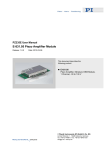
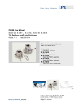
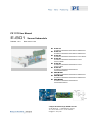
PZ 117E User Manual E-801 Release: 1.6.0 Sensor Submodule Date: 2010-11-22 E-801.10 Excitation and Readout Submodule for SGS Sensor E-801.15 Excitation and Readout Submodule for SGS Sensor E-801.20 Excitation and Readout Submodule for LVDT Sensor E-801.25 Excitation and Readout Submodule for LVDT Sensor, Master E-801.26 Excitation and Readout Submodule for LVDT Sensor, Slave E-801.30 Excitation and Readout Submodule for Piezoresistive Sensor E801B1007 Excitation and Readout Submodule for SGS Sensor E801B1008 Excitation and Readout Submodule for SGS Sensor E801B2008 Excitation and Readout Submodule for Piezoresistive Sensor © Physik Instrumente (PI) GmbH & Co. KG Auf der Römerstr. 1 ⋅ 76228 Karlsruhe, Germany Tel. +49 721 4846-0 ⋅ Fax: +49 721 4846-299 [email protected] ⋅ www.pi.ws Declaration of Conformity The E-801 is a plug-in submodule for different PZT controller/amplifiers. See the User Manual of the controller with which the submodule comes for the Conformity Declaration and Warranty Clauses applying to this product. Copyright 1999–2010 by Physik Instrumente (PI) GmbH & Co. KG, Karlsruhe, Germany. The texts, photographs and drawings in this manual enjoy copyright protection. With regard thereto, Physik Instrumente (PI) GmbH & Co. KG reserves all rights. Use of said text, photographs and drawings is permitted only in part and only upon citation of the source First printing 2010-11-22 Document Number PZ 117E, Release 1.6.0 E-801_User_PZ117E160.doc Eco, BRo This manual has been provided for information only and product specifications are subject to change without notice. Any change will be reflected in future printings. About this Document Users of this Manual This manual is designed to help the reader to install and operate the E-801 Sensor Submodule. It assumes that the reader has a fundamental understanding of basic servo systems, as well as motion control concepts and applicable safety procedures. The manual describes the physical specifications and dimensions of the E-801 Sensor Submodule as well as the software and hardware installation procedures which are required to put the associated motion system into operation. Updated releases of this document are available for download from www.pi.ws or email: contact your Physik Instrumente Sales Engineer or write [email protected]. Conventions The notes and symbols used in this manual have the following meanings: DANGER Indicates the presence of high voltage (> 50 V). Calls attention to a procedure, practice or condition which, if not correctly performed or adhered to, could result in injury or death. ! CAUTION Calls attention to a procedure, practice, or condition which, if not correctly performed or adhered to, could result in damage to equipment. NOTE Provides additional information or application hints. Related Documents The motion controller and the software tools which might be delivered with E-801 Sensor Submodule are described in their own manuals. Updated releases are available for download from www.pi.ws or email: contact your Physik Instrumente Sales Engineer or write [email protected]. Contents 1 Introduction 1.1 1.2 1.3 2 3 Safety Precautions .....................................................................2 Sensor Types .............................................................................3 Conventions for Solder Bridge Illustration ..................................3 Strain Sensor Submodules 2.1 2.2 2.3 2.4 2.5 4 18 LVDT Operating Element Summary (E-801.2x) ......................19 3.1.1 3.1.2 3.2 4 E-801.10 and E-801.15 Operating Element Summary...............4 E801B1007 Operating Element Summary .................................7 E801B1008 Operating Element Summary ...............................10 E-801.30 Operating Element Summary ...................................13 E801B2008 Operating Element Summary ...............................15 LVDT Sensor Submodules 3.1 2 Older Version (E-801.25 & E-801.26) ...................................... 19 SMD Version (E-801.20) .......................................................... 20 Alignment of Mechanical Zero of LVDT Sensors .....................22 E-801 Calibration Routines 23 Introduction 1 Introduction E-801 Sensor evaluation and excitation submodules are plug-in PCBs designed for use with a number of PI servo-control modules in the E-500 and E-600 series. The submodules normally come pre-installed on the modules/controllers with which they are ordered and the modules pre-installed in an appropriate PI chassis (except for OEM versions). The system is then calibrated at the factory with the associated PZT actuators. Accessing the elements described in this User Manual is necessary only if the controller/actuator configuration is changed or elements are replaced. Do not hesitate to consult with PI before proceeding with calibration procedures. 1.1 Safety Precautions DANGER Although there are no high voltages on E-801 submodules, only qualified personnel with special knowledge of handling high voltages should open the devices of which the E-801 is a part. Failure to heed warnings in this manual can result in bodily injury or material damage. ! CAUTION The E-801 plug-in submodule is an ESD-sensitive (electrostatic discharge sensitive) device. Observe all precautions against static charge buildup before handling this device. Avoid touching circuit elements, pins and PCB traces. Discharge any static charge you may have on your body by briefly touching a conductive, grounded object before you touch any electronic assembly. Pose PCBs only on conductive surfaces, such as ESD-safe transport containers (envelopes, foam). Electronic subassemblies must always be kept and transported/shipped in conductive packaging. www.pi.ws E-801 PZ 117E Release 1.6.0 Page 2 Introduction 1.2 Sensor Types E-801.10, E-801.15, E801B1007 and E801B1008 versions are used for excitation and evaluation of strain gauge sensors (SGS). The strain gauges are excited with DC signals and the evaluated signal is proportional to the expansion of the gauge. E-801.30 and E801B2008 versions are used for excitation and evaluation of piezoresistive sensors (semiconductor strain gauge sensors). The piezoresistive sensors are also excited with DC signals and the evaluated signal is proportional to the expansion of the gauge. With E801B1007, E801B1008, E-801.30 and E801B2008, there is an adjustable linearity correction circuit to correct the inherent non-linearity of strain sensors. E-801.20, .25 and .26 versions are used primarily with LVDT sensors, which require AC excitation. Master (E-801.25) and slave (E-801.26) versions are available to allow exact synchronization of the AC signals in multi-channel systems. It is also possible to bypass sensor excitation and signal processing altogether and feed in a 0-10 V signal from external sensor circuitry (e.g. E-852 sensor signal conditioner for singleplate capacitive sensors). There are no E-801 submodules for 2-plate capacitive sensors. Sensor excitation and readout for these sensors is implemented on the corresponding version of the various main modules (e.g. E-509.Cx or E-610.C0). 1.3 Conventions for Solder Bridge Illustration E-801 boards have solder bridges instead of jumpers. Both “single” and “double” solder bridges are used. NOTE In double bridges, the labeled top and bottom contacts share the same center contact. Fig. 1: Single and double solder bridges. X3 and X4 are shown closed with solder (here depicted in gray) and X6 open. www.pi.ws E-801 PZ 117E Release 1.6.0 Page 3 Strain Sensor Submodules 2 Strain Sensor Submodules 2.1 E-801.10 and E-801.15 Operating Element Summary E-801.10 and E-801.15 submodules provide DC sensor excitation and are used with strain gauge sensors (SGS). They differ in the output voltage provided for a display which may be present in the system (e.g. E-517 interface and display module): E-801.10: 0 to 2.5 V E-801.15: 0 to 10 V All settings of potentiometers and solder bridges on the E-801.10 and .15 are made at the factory during calibration and should not normally be adjusted by the end user. See figure below for details Gain is set with potentiometer R2 (“Gain”) and the bridge is balanced at the zero position with potentiometer R30 (“Sensor Tolerance”). A user adjustable, external zero potentiometer (“Zero”) is provided on the front or rear panel of the controller in which E-801 is integrated. The output of the preamplifier is an analog signal that is directly proportional to the piezo’s expansion and is also available at “Sensor Monitor” on the front or rear panel of the controller. Fig. 2: E-801.10 and .15 signal path diagram; Zero pot is on main module of controller www.pi.ws E-801 PZ 117E Release 1.6.0 Page 4 Strain Sensor Submodules R1 R2 R30 S1 (low-pass filter): 300 Hz 1 kHz 3 kHz Fig. 3: E-801.10 and .15, component side R1 R2 R30 Fig. 4: E-801.15, solder side, with corresponding drawing showing the solder bridges (with E-801.10, X3 is open and X2 closed, all other elements are identical to E-801.15) www.pi.ws E-801 PZ 117E Release 1.6.0 Page 5 Strain Sensor Submodules Settings and Adjustments Done via Sensor gain (“Gain”) R2 Sensor zero (“Sensor Tolerance”) R30 Adjustment for "Display” level (optional): R1 trim pot With E-801.10; adjustment pot R1 activated, display output range set to 0 to 2.5 V X2 closed, X3 open With E-801.15: adjustment pot R1 deactivated, display output range set to 0 to 10 V X3 closed, X2 open External signal mode (0-10 V)* X6 closed; X4, X5, X9 open Full-bridge mode (all 4 resistances on PZT) X6, X10, X11open, X4, X5, X9 closed Half-bridge mode X6 open, X4, X10, X11, X5, X9, closed Low-pass filter see S1 in figure above *External signal mode bypasses all sensor excitation and processing. www.pi.ws E-801 PZ 117E Release 1.6.0 Page 6 Strain Sensor Submodules 2.2 E801B1007 Operating Element Summary E801B1007 submodules provide DC sensor excitation and are used with strain gauge sensors (SGS). All settings of potentiometers and solder bridges on the E801B1007 are made at the factory during calibration and should not normally be adjusted by the end user. See figure below for details. Gain is set with potentiometer R2 (“Gain”) and the bridge is balanced at the zero position with potentiometer R30. Once R2 and R30 are adjusted properly, use only the external zero potentiometer for sensor zero-point adjustment (“Ext. Zero”; available on the front or rear panel of the controller in which E801B1007 is integrated). Linearity corrections are made with potentiometer R39. Via the X2 solder bridge, linearization is activated, and the polarity of the linearity correction is chosen. Depending on the setting of the X3 solder bridge, the output range for a display which is present in the system (e.g. E-517 interface and display module) can be 0 to 2.5 V or 0 to 10 V. The output of the preamplifier is an analog signal that is directly proportional to the piezo’s expansion and is also available as sensor monitor signal on the front or rear panel of the controller. Fig. 5: E801B1007 signal path diagram; Ext. Zero pot is on main module of the controller www.pi.ws E-801 PZ 117E Release 1.6.0 Page 7 Strain Sensor Submodules R1 X3 R2 R39 R30 S1 (low-pass filter): 300 Hz 1 kHz 3 kHz Fig. 6: E801B1007 component side R30 R39 R2 R1 Fig. 7: E801B1007, solder side, with corresponding drawing showing the solder bridges www.pi.ws E-801 PZ 117E Release 1.6.0 Page 8 Strain Sensor Submodules Settings and Adjustments Done via Sensor gain R2 Sensor zero balance R30 Adjustment for display level (optional): R1 trim pot Adjustment pot R1 activated, display output range set to 0 to 2.5 V X3 in position 2-3 Adjustment pot R1 deactivated, display output range set to 0 to 10 V X3 in position 1-2 Linearization correction: R39 Deactivated, R39 is ineffective X2 open Negative polarity (compression) X2 in position 1-2 Positive polarity (tension) X2 in position 2-3 External signal mode (0-10 V)* X6 1-2 closed; X4, X5, X9 open Full-bridge mode (all 4 resistances on PZT) X10, X11open, X4, X5, X9 closed Half-bridge mode X4, X10, X11, X5, X9, closed Low-pass filter see S1 in figure above *External signal mode bypasses all sensor excitation and processing. www.pi.ws E-801 PZ 117E Release 1.6.0 Page 9 Strain Sensor Submodules 2.3 E801B1008 Operating Element Summary E801B1008 submodules provide DC sensor excitation and are used with strain gauge sensors (SGS). All settings of potentiometers and solder bridges on the E801B1008 are made at the factory during calibration and should not normally be adjusted by the end user. Gain is set with potentiometer R2 (SGS sensors). The bridge is balanced at the zero position with potentiometer R30. Once R2 and R30 are adjusted properly, use only the external zero potentiometer for sensor zero-point adjustment (“Ext. Zero”; available on the front or rear panel of the controller in which E801B1008 is integrated). Linearity corrections are made with potentiometer R39. Via the X2 solder bridge, linearization is activated, and the polarity of the linearity correction is chosen. Depending on the setting of the X3 solder bridge, the output range for a display which is present in the system (e.g. E-517 interface and display module) can be 0 to 2.5 V or 0 to 10 V. The output of the preamplifier is an analog signal that is directly proportional to the piezo’s expansion and is also available as sensor monitor signal on the front or rear panel of the controller. Fig. 8: E801B1008 signal path diagram; Ext. Zero pot is on main module of the controller www.pi.ws E-801 PZ 117E Release 1.6.0 Page 10 Strain Sensor Submodules R1 X3 R2 S1 (low-pass filter): 300 Hz 1 kHz 3 kHz R39 R30 X16 X19 Fig. 9: E801B1008 component side; R46 is not populated Fig. 10: E801B1008 solder side with solder bridges www.pi.ws E-801 PZ 117E Release 1.6.0 Page 11 Strain Sensor Submodules Settings and Adjustments Done via Sensor gain R2 Sensor zero balance R30 Adjustment for display level (optional): R1 trim pot Adjustment pot R1 activated, display output range set to 0 to 2.5 V X3 in position 2-3 Adjustment pot R1 deactivated, display output range set to 0 to 10 V X3 in position 1-2 Linearization correction: R39 Deactivated, R39 is ineffective X2 open Negative polarity (compression) X2 in position 1-2 Positive polarity (tension) X2 in position 2-3 External signal mode (0-10 V)* X6 1-2 closed; X4, X5, X9 open Full-bridge mode (all 4 resistances on PZT) X10, X11 open, X4, X5, X9 closed Half-bridge mode X4, X10, X11, X5, X9, X19, X16 closed Low-pass filter see S1 in figure above *External signal mode bypasses all sensor excitation and processing. www.pi.ws E-801 PZ 117E Release 1.6.0 Page 12 Strain Sensor Submodules 2.4 E-801.30 Operating Element Summary E-801.30 submodules provide DC sensor excitation and are used with piezoresistive sensors (semiconductor strain gauge sensors). Gain is set with potentiometer R2 and the bridge is balanced at the zero position with potentiometer R30. These settings are made at the factory during calibration and should not normally be adjusted by the end user. A user adjustable, external zero potentiometer is provided on the front or rear panel of the controller. Linearity corrections are made with potentiometer R1. The polarity of the linearity correction can be chosen through the use of switch S2. These settings are made at the factory during calibration and should not normally be adjusted by the end user. Fig. 11: E-801.30 signal path diagram;Ext. Zero pot is on main module of the controller www.pi.ws E-801 PZ 117E Release 1.6.0 Page 13 Strain Sensor Submodules Fig. 12: E-801.30, component side Settings and Adjustments Sensor Gain1 R2 1 R30 Sensor Zero balance Linearization Correction 1 Linearization Polarity1 2 Low Pass Filter R1 S2 S1 Notes: 1 Factory set, do not change 2 See figure above for settings www.pi.ws E-801 PZ 117E Release 1.6.0 Page 14 Strain Sensor Submodules 2.5 E801B2008 Operating Element Summary E801B2008 submodules provide DC sensor excitation and are used with piezoresistive sensors (semiconductor strain gauge sensors). All settings of potentiometers and solder bridges on the E801B2008 are made at the factory during calibration and should not normally be adjusted by the end user. Gain is set with potentiometer R46. The bridge is balanced at the zero position with potentiometer R30. Once R46 and R30 are adjusted properly, use only the external zero potentiometer for sensor zero-point adjustment (“Ext. Zero”; available on the front or rear panel of the controller in which E801B2008 is integrated). Linearity corrections are made with potentiometer R39. Via the X2 solder bridge, linearization is activated, and the polarity of the linearity correction is chosen. Depending on the setting of the X3 solder bridge, the output range for a display which is present in the system (e.g. E-517 interface and display module) can be 0 to 2.5 V or 0 to 10 V. The output of the preamplifier is an analog signal that is directly proportional to the piezo’s expansion and is also available as sensor monitor signal on the front or rear panel of the controller. Fig. 13: E801B2008 signal path diagram; Ext. Zero pot is on main module of the controller www.pi.ws E-801 PZ 117E Release 1.6.0 Page 15 Strain Sensor Submodules R1 X3 R46 R39 R30 S1 (low-pass filter): 300 Hz 1 kHz 3 kHz Fig. 14: E801B2008 component side, R2 is not populated Fig. 15: E801B2008 solder side with solder bridges www.pi.ws E-801 PZ 117E Release 1.6.0 Page 16 Strain Sensor Submodules Settings and Adjustments Done via Sensor gain: R46 Sensor zero balance R30 Adjustment for display level (optional): R1 trim pot Adjustment pot R1 activated, display output range set to 0 to 2.5 V X3 in position 2-3 Adjustment pot R1 deactivated, display output range set to 0 to 10 V X3 in position 1-2 Linearization correction: R39 Deactivated, R39 is ineffective X2 open Negative polarity (compression) X2 in position 1-2 Positive polarity (tension) X2 in position 2-3 External signal mode (0-10 V)* X6 1-2 closed; X4, X5, X9 open Low-pass filter see S1 in figure above *External signal mode bypasses all sensor excitation and processing. www.pi.ws E-801 PZ 117E Release 1.6.0 Page 17 LVDT Sensor Submodules 3 LVDT Sensor Submodules The E-801.2x submodules provide AC sensor excitation and readout, as required by LVDT (linear variable differential transformer) sensors. Although primarily for use with LVDT sensors, AC excitation can also be used with SGS sensors. Installed amplifiers and filters allow adaptation of the submodule to different configurations of main board electronics. AC signals are amplified in a dual-stage preamplifier. The E-801.25 submodule is a master submodule, generating its own excitation frequency. The E-801.26 is a slave, using the excitation frequency of a master on the same module (SMD versions have master/slave jumper setting). Fig. 16: E-801.20 LVDT submodule sensor readout signal flow. Zero pot is on main module. NOTE On older (conventional) versions X14+X13 = J5, X8+X9=J6 and R2=R603. www.pi.ws E-801 PZ 117E Release 1.6.0 Page 18 LVDT Sensor Submodules 3.1 LVDT Operating Element Summary (E-801.2x) Different versions of the E-801.2x may still be encountered: older (conventional) versions designated E-801.25 (master) and E-801.26 (slave) and the current SMD version, E-801.20, which is jumper-settable as master or slave. 3.1.1 Older Version (E-801.25 & E-801.26) Jumpers J5 and J6 select between medium- and high-gain settings to optimize piezo performance. An analog signal is available at the output of the demodulator which is directly proportional to the piezo expansion (it appears at the Sensor Monitor connector on the front panel of most main modules in which the E-801 is used). This signal can be fine-tuned in amplitude with the gain potentiometer (R603) and zero-adjusted with a trim pot on the main module (do not confuse with P406 on an E-802 servo submodule). Full piezo expansion should be calibrated to occur at +10 V sensor output. Fig. 17: LVDT conventional (older) version (here E-801.25) with adjustment element location diagram www.pi.ws E-801 PZ 117E Release 1.6.0 Page 19 LVDT Sensor Submodules Settings and Adjustments 3.1.2 R603: Sensor gain J3: Jumper: Internal bridge completion 1-2: installed, 2-3: not installed J4: Jumper: Excitation capacitor coupled 1-2: C installed, 2-3: C not installed J5: Jumper: Gain pre-amplifier #1 1-2: high gain, 2-3: low gain J6: Jumper: Gain pre-amplifier #2 1-2: high gain, 2-3: low gain J7: Jumper: Excitation 1-2: direct, 2-3: one side grounded SMD Version (E-801.20) R1 R2 Master (open) / Slave (shorted) Sensor bridge measuring points, X18 pins 9&4, GND 6&8 Fig. 18: SMD version, component side; note jumper for master/slave setting makes the E-801.20 equivalent to either an 801.25 or an 801.26 www.pi.ws E-801 PZ 117E Release 1.6.0 Page 20 LVDT Sensor Submodules R1 R2 Fig. 19: SMD version, solder side, with corresponding drawing showing the solder bridges that replace the jumpers. Settings and Adjustments Sensor gain (factory set, do not change) R2 Adjustment for display level R1 Adjustment pot R1 activated, display output range set to 0 to 2.5 V X1 closed, X2 open Adjustment pot R1 deactivated, display output range set to 0 to 10 V X1 open, X2 closed Internal use (bandwidth setting) External signal mode (0-10 V) * www.pi.ws * X4, X5, X7, X11, X12 None: Use E-801.15 High-gain range X14 & X8 closed X13 & X9 open Low-gain range X14 & X8 open X13 & X9 closed Sensor gain R2 Off-board zero potentiometer enable/disable X3: closed = enabled X3: open = disabled External signal mode bypasses all sensor excitation and processing. E-801 PZ 117E Release 1.6.0 Page 21 LVDT Sensor Submodules 3.2 Alignment of Mechanical Zero of LVDT Sensors Models connected to LVDT sensors may need to have the mechanical zero-point of the sensor adjusted. LVDT sensor readout is based on differential measurement of the inductive excitation of two secondary coils with a common, moving, ferrite core. The first step of the alignment procedure is to balance the bridge by moving the ferrite core (probe) to the zero position. To verify the balance of the bridge, display the two sinusoidal voltages on a 2-channel oscilloscope. On both the conventional and SMD versions, these signals can be found on connector X18, pin 9 and pin 4 (see Fig. 17 and Fig. 18), or on pins 2 and 3 of the sensor’s LEMO connector. Ground is on X18 pins 6 & 8 and on the LEMO shield. If the bridge is balanced properly, both sine curves have the same amplitude and phase. If there is any deviation, move the LVDT mechanically until both curves become identical. www.pi.ws E-801 PZ 117E Release 1.6.0 Page 22 E-801 Calibration Routines 4 E-801 Calibration Routines Systems containing an E-801 submodule are delivered precalibrated with the PZTs and for the intended application. Be sure to connect the PZTs as indicated with the labels on the system chassis. Except for zero adjustment via the corresponding potentiometer on the front or rear panel of the electronics chassis, recalibration is only necessary if modules, submodules or PZTs are exchanged or modified, or if operating conditions (e.g. temperature range) are drastically altered. For calibration, the E-801 submodule must be installed on the module with which it is to be used. The same PZT actuators must be connected to the system and loaded with the same loads they have to move in the application. Because successful E-801 calibration requires proper configuration of the module on which the E-801 is installed (e.g. servo mode, remote operation, ...), the exact procedure to follow is described in the manual for that module. www.pi.ws E-801 PZ 117E Release 1.6.0 Page 23