1
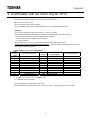
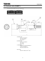
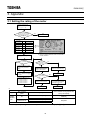
E6581530② TOSVERT VF-AS1 Instruction manual with V3 motor VFAS1+Vector option[VEC007Z] with V3 motor E6581530② - Contents - 1. Comparison with VF-V3 (VFAS1+PG feedback) ......................................................................................................................2 2. Combination with the motor only for VFV3 ...............................................................................................................................5 2.1 Parameter settings..............................................................................................................................................................6 2.2 Standard connection for VFAS1 and V3 motor ...................................................................................................................7 2.3. Optional cable (CABV07)...................................................................................................................................................8 2.4. Optional cable (CAB011) ...................................................................................................................................................9 3. Appendix.................................................................................................................................................................................10 3.1 Setting the rating of the motor...........................................................................................................................................10 3.2 Explanation of motor parameter........................................................................................................................................ 11 3.3 Accuracy of torque control ................................................................................................................................................12 3.4 Notes on the vector control ...............................................................................................................................................13 1 E6581530② 1. Comparison with VF-V3 (VFAS1+PG feedback) [Specifications, functions] Series name Output capacity Overload rating Control method Control function Main power supply 200V class 400V class Control function Rated Speed Maximum motor speed Maximum output frequency Speed control range Speed rate of Speed control change Speed instruction input Kind of input pulse Positioning Maximum control frequency Electronic gear setup Torque control / Torque operation input Acceleration/ Deceleration time setting Switching control mode Preset speed Braking method Torque limit(Current limiting function) Speed limit Snap stop control Trip history monitor Applied load GD2 PWM carrier frequency Contact output signal Low speed detection Reach fixed speed/ finished positioning Standby Current limiting Fault Fault code Positioning/ Speed feed back pulse output TOSVERT VF-AS1 + PG feedback option 200V: 0.4 ~ 75kW 400V: 0.75 ~ 500kW 150%-60sec TOSVERT VF-V3 200V: 2.2 ~ 55kW Digital setting: +/-0.01% Analog setting: +/-0.3% 0 - +/-10Vdc / Maximum speed 0 - +10Vdc / Maximum speed 4-20mAdc / Maximum speed Impossible to use a positioning control. Digital setting: +/-0.01% Analog setting: +/-0.1% 0 - +/-10Vdc / Maximum speed (Possible to adjust internal setting) 150%-60sec, 200%-2sec (up to 11kW) PWM control PWM control [Vector control, Digital current control for all [Vector control, Digital current control for all range] range] Speed/ Torque Speed/ Torque/ Positioning 3ph- 200~240V-50/60Hz 3ph- 200~220V-50/60Hz 3ph-380~480V-50/60Hz over 110kW: 3ph-380~440-50Hz 3ph-380~480-60Hz -1 -1 60Hz/1800 min (4 pole) *1 1500min -1 -1 80Hz/2400 min (4 pole) *1 2400min 80Hz *2 80Hz 1:1000 1:1000 Forward pulse / reverse pulse sequence 160kpps 100 ~ 400 ppr / 1 rotation 0 - +/-10Vdc 0 - +/-10Vdc 0.1-6000sec(Straight/ S character) 0.0-60.0sec(Straight/ S character) Possible to switch Possible to switch 15 preset speed maximum Dynamic brake(resistor) or Re-generating to power supply by RC7 series * Braking resistor: Option Possible to adjust internal setting or external signal. Without temperature compensation Enabled to use torque limit function Before the past 4 times 100 or less times of a motor GD2 1.0 ~ 16.0kHz over 200V-55kW, 400V-90kW 2.5 ~ 8.0kHz Low speed detection Reach fixed speed/- 3 preset speed Dynamic brake(resistor) or Re-generating to power supply by RC7 series * Resistor is option devices over 22kW Possible to adjust internal setting or external signal. With temperature compensation Electronic gear(for positioning control) Enabled Before the past 8 times 20 or less times of a motor GD2 up to 11kW: 8kHz fixed over 15kW: 2kHz fixed Standby Over torque alarm Fault (All trip code or without EF, OCL trip) [1c relay output, open collector output] Standby Current limiting Fault (All trip code) [Open collector output] OFF: Fault ON: Normal Fault code(4 bit) Fault code (2 bit + 4(option) bit) - Low speed detection Reach fixed speed/ finished positioning Encoder signal (A, B phase: 1000ppr, Z phase: 1ppr) *1 Depends on Motor design and setting of carrier frequency *2 Possible control up to 120Hz with vector control with specific motor (Possible control 500Hz with V/f control.) *3 VFAS1’s software version (CPU1 version) should be over V124 (shipped after Mar,2006). *4 VFAS1 doesn’t support a positioning control function. 2 E6581530② Series name Analog output Adjust method Monitor Monitoring function Protection Communication Standard SINK/ SOURCE switching TOSVERT VF-AS1 + PG feedback option 2 output circuit(0-10V) + 2 output by option(+/-10V, 0-20mA) (Select from 64 functions) 7 touch key operation with operation panel 7 segment LED - RR input - Frequency at trip - VI/II input - Status - RX input - Output frequency - Operation frequency - AI1 input - FM output - Output current - AM output - DC-bus voltage - Fixed output for meter - Output voltage adjustment - Compensated - Input terminal Info. frequency - Speed feedback (real - Output terminal Info. - CPU1 version time) - Speed feedback (1 - CPU2 version - Past trip 1~4 sec filtering) - Part replacement - Output torque alarm - Operation torque - Cumulative operation - Exciting current time - PID feedback value - Motor overload rate etc. - Inverter overload rate - PBR overload rate - Input power - Output power - Failure of current - Over current while detection circuit acceleration - Failure of optional devices - Over current while - Low output current deceleration - Low input - Over current while voltage(Main power/ constant speed - Over current when Control power) - Over torque starting - Earth fault - U-arm over current - Failure of auto-tuning - V-arm over current - W-arm over current - Failure of inverter’s type-form - Input phase failure - Output phase failure - Failure of initialize - Failure of RAM - Over voltage while - Failure of ROM acceleration - Failure of CPU1 - Over voltage while - Failure of CPU2 deceleration - Over voltage while etc. constant speed - Over load for inverter - Over load for motor - Over heat - Emergency stop - Failure of EEPROM - PBR over current - PBR over load - Failure of CPU - Failure of communication command - Failure of SINK/SOURCE switching - Failure of operation keys RS485 standard (Toshiba protocol, MODBUS-RTU) OPTIONAL devices: DeviceNet Profibus-DP, CC-LINK etc. CE, UL Enabled 3 TOSVERT VF-V3 2 output(+/-10V) (Speed/ torque or Torque / output current) 5 touch key operation + 1 reset switch 7 segment LED - Standby ON/OFF indication - Operation speed - Speed - Torque - Information of input terminal - History of trip - Over Current - Over voltage - Low input voltage - Over load - Over heat/ Failure of regeneration - Failure of sensor - Over speed - Over Position deviation - Motor restraint - Over travel - Failure of parameter setting RS232C, RS485 with Optional device “P CU10(card for positioning)” none none E6581530② [Comparison of characteristics] Series name Control method Vector control with sensor Starting torque Motoring Regenerating Speed presumption system Zero speed torque Speed control range Speed control accuracy (Digital setting) Speed response PG specifications Torque control Torque control range (Torque value) Speed response while torque control Accuracy of torque control Speed range of torque limit Motoring Regenerating Auto-restart Regenerative power ride-though control TOSVERT VF-AS1 + PG feedback option TOSVERT VF-V3 Current vector control PG feedback (*1), Without temperature sensor 0Hz-200% Sensor-less: 0.5Hz-200% Enable Enable (Disable when sensor-less) Slip frequency presumption from torque current 1:1000 Sensor-less 1:200 *2 +/-0.02% *3 Sensor-less +/-0.5% *4 ~ 90 rad/s Sensor-less ~90rad/s *5 - 1000ppr - Line drive system(5V) or Complementary(12V, 15V, 24V) - 300kHz of maximum input pulse frequency Enable without temperature compensation -100~100% Current vector control PG feedback with temperature sensor - 1000oor - Line drive system(5V) - 40kHz(60kHz) of maximum input pulse frequency Enable -100~100% All range All range +/-10% (When motor temperature is hot.) All range (Sensor-less 1:100) *6 All range (Sensor-less 1:50) *6 Enable Enabled +/-10% (With motor temperature detection) All range up to 11kW: 0Hz-200% over 15kW: 0Hz-150% Enable Enable Slip frequency presumption from torque current 1:1000 (only PG feedback) +/-0.01% (only PG feedback) 60rad/s Enable only speed or torque control none *1 VF-AS1: The inverter’s capacity is larger than motor’s (1 rank-up) *2 VF-AS1: This is over 3.7kW of inverter and motor capacity. (Depends on rated slip frequency) *3 VF-AS1: The base frequency is 60Hz setting. *4 VF-AS1: About 10% of rated slip *5 Fine-tuned relation parameter. *6 Sample value because these range depend on the motor characteristics. 4 E6581530② 2. Combination with the motor only for VFV3 The VF-AS1 is possible to operate V3 motor with next optional devices. [Speed control, Torque control] Vector control option with sensor: VEC007Z * VFAS1’s software version (CPU1 version) should be over V124 (shipped after Mar,2006). [NOTICE] - The VF-AS1’s capacity is larger than V3 motor’s. (1 rank or 2 rank-up) - To install dynamic braking resistor(option) when the machine need large regenerative torque. It is necessary to install large capacity of resistor in next condition. 1. Short time cycle of acceleration and deceleration 2. Large load inertia - The VEC004~6Z can’t use for V3 motor which PG specifications is line driver output. - VFAS1 doen’t support a positioning control function. Therefore, VFAS1 combination with the V3 motor can’t perform a positioning control. [Table of VFAS1 and V3 motor combination] Output capacity (kW) 2.2 3.7 5.5 7.5 11 15 22 30 37 45 55 V3 motor’s type-form Case number IK-EBKM8-VFV3 IK-EBKM8-VFV3 IKK-EBKM8-VFV3 IKK-EBKM8-VFV3 IKK-EBKM8-VFV3 IKK-EBKM8-VFV3 TIK-EBKM8-VFV3 TIK-EBKM8-VFV3 TIK-EBKM8-VFV3 TIK-EBKM8-VFV3 TIK-EBKM8-VFV3 100L 112M 132S 132M 160M 160L 180M 180L 200L 200L 225S VFAS1 specifications VFAS1-2037PL VFAS1-2055PL VFAS1-2075PL VFAS1-2110PM VFAS1-2150PM VFAS1-2185PM VFAS1-2300PM VFAS1-2370PM VFAS1-2450PM VFAS1-2550P VFAS1-2750P VFV3 specifications VFAS1-2055PL VFAS1-2075PL VFAS1-2110PM VFAS1-2150PM VFAS1-2185PM VFAS1-2220PM VFAS1-2370PM VFAS1-2450PM VFAS1-2550P VFAS1-2750P - *1 The type-form of V3 motor is Leg attachment type. *2 Load reduction may be needed. VFAS1 specifications: Overload rating: 150%-1min VFV3 specifications: Overload rating: 150%-1min, 215%-0.5sec. The starting torque is 200%~300%. 5 E6581530② 2.1 Parameter settings To use VFAS1 with V3 motor, these parameter setting are needed. * It is necessary to set others parameter for torque control. [Parameter setting for motor] About motor setting parameter, please execute auto-tuning by next method. (1) Set next parameter by motor’s name plate. Title Function Base frequency vl Voltage at base frequency vlv Motor rated capacity *1 f405 Motor rated current f406 Motor rated rotation f407 *1: Set using VFV3 motor’s capacity. Setting range 25.0 - 500 Hz 50 - 330 V / 50 – 660 V 0.10 - 500 kW 0.1 - 2000 A 100 - 60000 min-1 Setting value 52 160 Depends on capacity Depends on capacity Depends on capacity (2) Please execute F400(Auto-tuning 1) = 4 (Auto calculation of motor const) (3) After motor wiring, please set F400 = 2(Auto-tuning and run) and input the operation signal. The motor const setting is finished above method. [Parameter setting] Title pb pbr Function Selection of V/f control Selection of electric thermal characteristics Selection of Dynamic brake PBR value 0: Disabled , 1: Enabled 1.0 - 1000 ohm pbcp PBR capacity 0.01 - 600 kW f240 Starting frequency f307 Selection of base frequency voltage 0.0 - 10.0 Hz 0: Without power supply voltage compensation Without output voltage limit 1: With power supply voltage compensation Without output voltage limit 2: Without power supply voltage compensation With output voltage limit 3: With power supply voltage compensation With output voltage limit 12 - 9999 pt olm f375 f606 Setting range 0-8 0-7 Setting value 8 4 1 (Note 1) Depends on capacity (Note 1) Depends on capacity (Note 1) Pulse number of PG input OL reduction starting frequency 0.0 - 30.0 Hz 0.0 1 (Note 2) 1000 0.0 Note 1: It is necessary to set to use the braking resistor. Note 2: In case of pt = 2~4, 6~8, the function of ‘power supply voltage compensation’ is always enabled. [Others parameter setting] About current/ speed control gain, please refer “E6581333: Current and speed control gain adjustment method”. 6 E6581530② 2.2 Standard connection for VFAS1 and V3 motor This connection diagram is for VFAS1 and VEC007Z(Vector control option with sensor). When you select torque control, it is necessary to wire others connection. MCCB THR Noise filter (OPTION) AC reactor DC reactor Braking resistor (OPTION) (OPTION) (OPTION) MCCB MC Power PA P0 FAN U/T1 S/L2 V/T2 T/L3 Stand-by ST Forward F Reverse R U V F E K J M L H G P N VEC007Z A NA B NB PGVC PGCC CC MOT W W/T3 S0 Note 1 [Power Supply] 3ph-200~240V-50/60Hz FV FW PA PB R/L1 R0 FU E SENSOR Encoder E VFAS1 Note 2 V3 motor Note1 To divide the wiring between main power and control power, it is necessary to install CPS002Z(Backup unit of control power supply). Note2 When using V3 motor cable (RAD320-CA1), please use connection relay cable (CABV07). When connect the new VFV3 motor, please select CAB011 instead of RAD320-CA1 and CABV07. Note3 The detail explanation for VEC007Z, please refer attached user’s manual for VEC007Z(E6581319). 7 E6581530② 2.3. Optional cable (CABV07) VFAS1 option VEC007Z To Inverter’s G/E terminal VFV3 sensor cable CABV07 RAD320-CA1 SIGNAL SIGNAL WIRE COLOR NUMBER NAME 6 PGCC Black Red 5 PGVC Black/White Red/White 4 NB Green 3 B Green/White 2 NA Yellow 1 A Yellow/White To connect each wire to terminal block. 8 E6581530② 2.4. Optional cable (CAB011) The Optional cable ‘CAB011’ has 3 type of cable length. Type-form CAB011-10M CAB011-20M CAB011-30M Cable length(m) 10m 20m 30m Shrinkage tube Shrinkage tube A: Shielded cable Cable: UL1015 AWG18 Color: Green/Yellow Amp: R1.25-5 B: Shielded cable Cable: UL1015 AWG12 Color: Green Amp: 3.5-5S C: RA23 sensor Straight plug: JL02-68-20-B29SC-F0 Contact: 031-50968-010 Cable clump: MS3057-12A Sensor cable: 2 Cable: KVC-36SB, 0.2mm , 4-pair 9 E6581530② 3. Appendix 3.1 Setting the rating of the motor Operation in automatic torque boost mode or vector control mode (RV=, , , , ) Is the motor Toshiba standard four-pole motor with the same capacity rating as the inverter? Is the motor cable 30m or less in length? *1 YES End NO Set the following parameters, as specified on the motor nameplate. Nameplate Title Setting range information Base frequency XN ~Hz Base frequency ~ (200V) XNX ~ (400V) voltage Rated capacity ~kW H of motor Motor rated ~A H current Motor rated ~ H min-1 speed *2: No problem even if the motor is not connected. *3: It does not matter whether the motor is under load or no-load conditions. Set H at *2 (After execution, the setting returns to .) NO GVP is displayed. *3 Is the motor actually connected and in a standby state? YES The base frequency or the rated rotational speed of the motor is not set correctly. Check their settings. Enter the correct value for XN or H, and then set H to again. The following parameters have been calculated and set. H Motor constant 1 H Motor constant 2 H Motor constant 3 H Motor constant 4 NO YES Check the precautions to be taken whe n setting the auto tuning parameter to 1, and if no problem is found, then set H to and start operation. Make necessary settings, as specified in (1) Setting auto-tuning. End GPV or GPV is displayed. YES NO H and H have been tuned to the motor connected. Parameters H and H use the value calculated automatically by the inverter. End End *1: Motor used Type Toshiba standard motor No. of motor poles 4P Other than 4P Capacity Same as the inverter capacity Different from the inverter capacity Same as the inverter capacity Different from the inverter capacity Tuning required or not (Yes in flowchart: Tuning required, No: Tuning not required) * Not required (tuned to factory defaults) Required Others * When using a long cable (guide: 30m or over), be sure to make auto-tuning 1 (f400 = 2). 10 E6581530② 3.2 Explanation of motor parameter This section describes how to set motor constants. Select the items to be improved and change the related motor constants. (1) Slip frequency gain f401 This parameter is to adjust the slippage of the motor. Setting this parameter at a larger number can reduce the slippage of the motor. However, setting it at an excessively large number may result in hunting, etc., and thus cause an unstable operation. (2) Motor constant 1 f410(Torque boost) (Motor test reports may be useful.) This parameter is to adjust the primary resistance of the motor. Setting this parameter at a larger value can prevent the drop of the motor torque in low speed ranges due to a voltage drop. However, setting it at an excessively large number may result in large current in low speed range and appearance of an overload trip, etc. (3) Motor constant 2 f411(No-load current) (Motor test reports may be useful.) This parameter is to adjust the exciting inductance of the motor. The larger the set value, the more exciting current can be increased. Note that specifying a too large value for the motor constant may cause hunting. (4) Motor constant 3 f412 (Leak inductance) (Motor test reports may be useful.) This parameter is to adjust the leakage inductance of the motor. The larger the set value, the larger torque the motor can produce in high-speed ranges. (5) Motor constant 4 f413 (Rated slip) This parameter is to adjust the secondary resistance of the motor. The amount of compensation for slip increases with increase in this value. (6) f460 (Speed loop proportional gain) This parameter is to adjust the gain responsive to speed. Specifying a large gain increases the speed of response, but specifying an excessively large gain may result in the occurrence of hunting. If operation is unstable and hunting occurs, operation can be stabilized in most cases by reducing the gain. (7) f462 (Moment of inertia of load) This parameter is used to adjust the excess response speed. Specifying a large value reduces the amount of overshoot at the completion of acceleration. So, specify a value appropriate to the actual moment of inertia of the load. 11 E6581530② 3.3 Accuracy of torque control - Sensor-less vector control. (Inverter’s capacity is same as motor’s.) Control range 1:20 100% Torque +/-30% (+/-10% over 30% +/-20% (+/-10%) +/-10% (+/-5%) +/-30% (+/-10%) 0 90 (+/-30%) 360 Over +/-30% 900 1800 +/-30% (+/-10%) +/-20% (+/-10%) -1 Speed[min ] +/-30% (+/-10%) +/-30% -100% Control range 1:5 0.4Hz - Vector control with sensor. (Inverter’s capacity is same as motor’s.) Torque In with a standard motor + sensor, continuation operation cannot be performed in this domain. 100% 70% 50% +/-10% +/-10% Speed 10% 0 100% 5% Base frequency +/-10% -50% The highest permission operation frequency +/-10% -70% -100% 12 E6581530② 3.4 Notes on the vector control 1) To use vector control mode (pt= 8) with V3 motor, enter each motor constant indicated on the nameplate (vl (base frequency), vlv (base-frequency voltage), f405 (rated capacity of motor), f406 (rated current of motor) and f407 (rated number of revolutions of motor) ), read the precautions on auto-tuning 1 on section 6.22 (1) in E6581442, and then set f400 to 2 (auto-tuning). 2) The sensorless vector control exerts its characteristics effectively in frequency areas below the base frequency (vl). The same characteristics will not be obtained in areas above the base frequency. 3) When driving V3 motor, it is necessary to select capacity of VFAS1 larger than V3's. ex. 200% output torque: 1 class-up, 300% output torque: 2 class-up 4) Always operate the motor in single operation (one inverter to one motor). Sensorless vector control cannot be used when one inverter is operated with more than one motor. 5) The torque produced by the motor decreases more or less around the rated frequency because of a voltage drop cause motor-generated torque in the vicinity of rated frequency to be somewhat lower. 6) Connecting a reactor or surge voltage suppression filter between the inverter and the motor may reduce motor-generated torque. Setting auto-tuning 1 may also cause a trip (etn, etn1 ~ 3)rendering sensorless vector control unusable. In the event of a trip, perform auto-tuning with the inverter connected directly to the motor, or enter the motor constant calculated from the motor test results. 7) Connect speed sensor for vector control with sensor to the motor. Connecting via gear, etc. causes motor's oscillating or inverter's trip by lack of rigidity. 13